Version: TV0.1 (Tentative)
TECHNICAL SPECIFICATION
MODEL NO: 10.3inch e-Paper (D)
The content of this information is subject to be changed without
notice. Please contact Waveshare for further information.
Customer’s Confirmation
Customer
Date
By
E Ink’s Confirmation
Dep
PM
PjM
FAE
Panel
Design
Electronic
Mechanical
Product
Design
Design
Verification
Prepared
By
Sign
10.3inch e-Paper (D)www.waveshare.com1/19�
Issued Date
Rev.
TV0.1 Feb/16,2016
Revised
Tentative
Contents
Revision History
10.3inch e-Paper (D)www.waveshare.com2/19�
TECHNICAL SPECIFICATION
PAGE
1
2
3
4
4
CONTENTS
ITEM
Cover
Revision History
Contents
General Description
Features
Mechanical Specifications
Mechanical Drawing of EPD module
Input/Output Terminals
Electrical Characteristics
Power on Sequence
Refresh Rate
Optical Characteristics
Handling, Safety and Environment Requirements and Remark
Reliability test
Block Diagram
Packing
NO.
-
-
-
1
2
3
4
5
6
7
8
9
10
11
12
13
10.3inch e-Paper (D)www.waveshare.com3/19�
1. General Description
10.3inch e-Paper (D) is a reflective electrophoretic E Ink and Mobius technology display module
based on active matrix TFT substrate. It has 10.3” active area with 1404 x 1872 pixels, the display is
capable to display images at 2-16 gray levels (1-4 bits) depending on the display controller and the
associated waveform file it used.
2. Features
� High contrast reflective/electrophoretic technology
� 1404x 1872 Mobius display
� Ultra wide viewing angle
� Ultra low power consumption
� Pure reflective mode
� Bi-stable
� Commercial temperature range
� Landscape, portrait mode
3. Mechanical Specifications
Parameter
Screen Size
Display Resolution
Active Area
Pixel Pitch
Pixel Configuration
Outline Dimension
Module Weight
Number of Gray
Specifications
10.3
1404(H) × 1872(V)
157.248(H) ×209.664 (V)
0.112(H) ×0.112(V)
Rectangle
165.8(H) × 227.70(V) ×0.647(D)
TBD
16 Gray Level (monochrome)
Remark
Unit
Inch
Pixel
mm
mm
mm
g
Display operating mode
Reflective mode
10.3inch e-Paper (D)www.waveshare.com4/19�
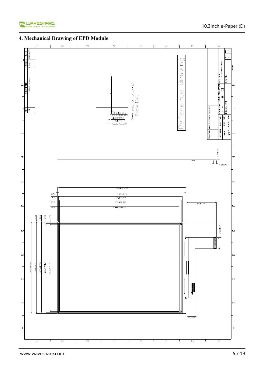
4. Mechanical Drawing of EPD Module
10.3inch e-Paper (D)www.waveshare.com5/19�
5. Input/Output Interface
5-1)Pin Assignment
Connector type:196033-40041
Pin #
1
2
3
4
5
6
7
8
9
10
11
12
13
14
15
16
17
18
19
20
21
22
23
24
25
26
27
28
29
30
31
32
33
34
35
36
37
38
39
40
Signal
VGL
NC
VGH
NC
VDD
MODE
CKV
SPV
VSS
VCOM
VDD
VSS
XCL
D0
D1
D2
D3
D4
D5
D6
D7
VSS
D8
D9
D10
D11
D12
D13
D14
D15
XSTL
XLE
XOE
NC
NC
VPOS
NC
VNEG
NC
Border
Description
Remark
Negative power supply gate driver
NO Connection
Positive power supply gate driver
NO Connection
Digital power supply drivers
Output mode selection gate driver
Clock gate driver
Start pulse gate driver
Ground
Common voltage
Digital power supply drivers
Ground
Clock source driver
Data signal source driver
Data signal source driver
Data signal source driver
Data signal source driver
Data signal source driver
Data signal source driver
Data signal source driver
Data signal source driver
Ground
Data signal source driver
Data signal source driver
Data signal source driver
Data signal source driver
Data signal source driver
Data signal source driver
Data signal source driver
Data signal source driver
Start pulse source driver
Latch enable source driver
Output enable source driver
NO Connection
NO Connection
Positive power supply source driver
NO Connection
Negative power supply source driver
NO Connection
Border connection
10.3inch e-Paper (D)www.waveshare.com6/19�
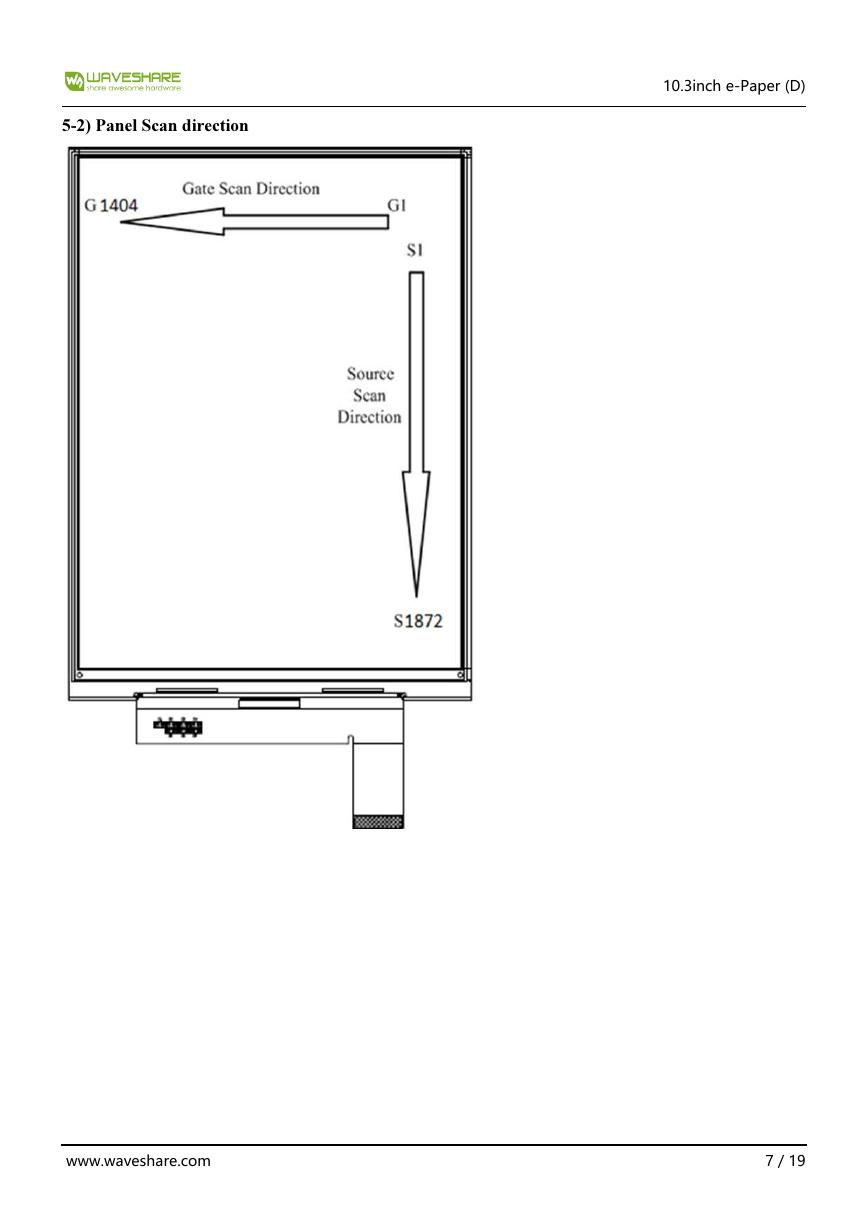
5-2) Panel Scan direction
10.3inch e-Paper (D)www.waveshare.com7/19�
7. Electrical Characteristics
7-1) Absolute Maximum Ratings:
Parameter
Symbol
Logic Supply Voltage
Positive Supply Voltage
Negative Supply Voltage
VDD
VPOS
VNEG
Max .Drive Voltage Range VPOS - VNEG
Supply Voltage
Supply Voltage
VGH
VGL
Supply Range
VGH-VGL
Operating Temp. Range
Storage Temperature
TOTR
TSTG
Rating
-0.3 to +5
-0.3 to +18
+0.3 to -18
36
-0.3 to +46
-25 to +0.3
-0.3 to +46
0 to +50
-25 to +70
7-2) Panel DC Characteristics
Symbol
Conditions
Min
VDD=3.3V
VGL =-20V
VGH = 25V
VNEG = -15V
VPOS = 15V
-
3.0
-
-21
-
24
-
-15.4
-
14.6
-
-
Parameter
Signal ground
Logic Voltage supply
Gate Negative supply
Gate Positive supply
Source Negative supply
Source Positive supply
Border supply
Asymmetry source
Common voltage
Panel Power
Standby power panel
VSS
VDD
IVDD
VGL
IGL
VGH
IGH
VNEG
INEG
VPOS
IPOS
VCOM
VAsym
VCOM
ICOM
P
PSTBY
V
V
V
V
V
V
V
℃
℃
Typ
0
3.3
TBD
-20
TBD
25
TBD
-15
TBD
15
TBD
Adjusted
Unit
Remark
--
--
--
--
--
--
--
--
--
Max
Unit
-
3.6
-
-19
-
26
-
-14.6
-
15.4
-
-
V
V
mA
V
mA
V
mA
V
mA
V
mA
V
mV
V
mA
mW
mW
VPOS+VNEG
-800
0
800
-
-
-
-
Adjusted
TBD
TBD
-
-
-
-
-
- The maximum power consumption is measured using 85 Hz waveform with following pattern transition:
from pattern of repeated 1 consecutive black scan lines followed by 1 consecutive white scan line to that
of repeated 1 consecutive white scan lines followed by 1 consecutive black scan lines. (Note 7-1)
- The Typical power consumption is measured using 85 Hz waveform with following pattern transition:
from horizontal 4 gray scale pattern to vertical 4 gray scale pattern. (Note 7-2)
- The standby power is the consumed power when the panel controller is in standby mode.
10.3inch e-Paper (D)www.waveshare.com8/19�




 V2版本原理图(Capacitive-Fingerprint-Reader-Schematic_V2).pdf
 摄像头工作原理.doc
 VL53L0X简要说明(En.FLVL53L00216).pdf
 原理图(DVK720-Schematic).pdf
 原理图(Pico-Clock-Green-Schdoc).pdf
 原理图(RS485-CAN-HAT-B-schematic).pdf
 File:SIM7500_SIM7600_SIM7800 Series_SSL_Application Note_V2.00.pdf
 ADS1263(Ads1262).pdf
 原理图(Open429Z-D-Schematic).pdf
 用户手册(Capacitive_Fingerprint_Reader_User_Manual_CN).pdf
 CY7C68013A(英文版)(CY7C68013A).pdf
 TechnicalReference_Dem.pdf