SIM8200EA-M2
Hardware Design
5G Module
SIMCom Wireless Solutions Limited.
Building B, SIM Technology Building, No.633, Jinzhong Road
Changning District, Shanghai P.R.China
Tel: 86-21-31575100
support@SIMcom.com
www.SIMcom.com
�
SIM8200EA-M2 Hardware Design V1.03
Document Title:
Version:
Date:
Status:
SIM8200EA-M2 Hardware Design
V1.03
2020-06-05
Released
GENERAL NOTES
SIMCOM OFFERS THIS INFORMATION AS A SERVICE TO ITS CUSTOMERS TO SUPPORT THE
APPLICATION AND ENGINEERING EFFORTS THAT USE THE PRODUCTS DESIGNED BY SIMCOM.
THE INFORMATION PROVIDED IS BASED ON THE REQUIREMENTS SPECIFICALLY FROM THE
CUSTOMERS. SIMCOM HAS NOT UNDERTAKEN ANY INDEPENDENT SEARCH FOR ADDITIONAL
RELEVANT INFORMATION, INCLUDING ANY INFORMATION THAT MAY BE IN THE CUSTOMER’S
POSSESSION. FURTHERMORE, THE SYSTEM VALIDATION OF THE PRODUCT DESIGNED BY
SIMCOM WITHIN A LARGER ELECTRONIC SYSTEM REMAINS THE RESPONSIBILITY OF THE
CUSTOMER OR THE CUSTOMER’S SYSTEM INTEGRATOR. ALL SPECIFICATIONS SUPPLIED
HEREIN ARE SUBJECT TO CHANGE WITHOUT NOTICE.
COPYRIGHT
THIS DOCUMENT CONTAINS THE PROPRIETARY TECHNICAL INFORMATION WHICH IS THE
PROPERTY OF SIMCOM LIMITED, COPYING OF THIS DOCUMENT, GIVING IT TO OTHERS, THE
USING OR COMMUNICATION OF THE CONTENTS THEREOF ARE FORBIDDEN WITHOUT THE
OFFICIAL AUTHORITY BY SIMCOM. OFFENDERS ARE LIABLE TO THE PAYMENT OF THE DAMAGES.
ALL RIGHTS ARE RESERVED IN THE EVENT OF GRANT OF A PATENT OR THE REGISTRATION OF A
UTILITY MODEL OR DESIGN. ALL SPECIFICATIONS SUPPLIED HEREIN ARE SUBJECT TO CHANGE
WITHOUT NOTICE.
SIMCom Wireless Solutions Limited
Building B, SIM Technology Building, No.633 Jinzhong Road, Changning District, Shanghai P.R.China
Tel: +86 21 31575100
Email: SIMcom@SIMcom.com
For more information, please visit:
https://www.SIMcom.com/download/list-863-en.html
For technical support, or to report documentation errors, please visit:
https://www.SIMcom.com/ask/ or email to: support@SIMcom.com
Copyright © 2020 SIMCom Wireless Solutions Limited All Rights Reserved.
www.simcom.com 2 / 71
�
SIM8200EA-M2 Hardware Design V1.03
Version History
Data
Version
2019-06-27
2019-09-25
2019-12-19
2020-06-05
1.00
1.01
1.02
1.03
Description of change
original version
Modify the error
Antenna interfaces update
Modify table 3
Modify the error
Modify the format
Author
Olivier.wu
Xutao.jiang
Cunbao.feng
Olivier.wu
Yibo.zhong
Yao.chen
www.simcom.com 3 / 71
�
SIM8200EA-M2 Hardware Design V1.03
Contents
Contents ................................................................................................................................................ 4
Table Index ............................................................................................................................................ 6
Figure Index .......................................................................................................................................... 8
1. Introduction ...................................................................................................................................... 9
1.1 Product Outline ................................................................................................................................ 9
1.2 Hardware Block Diagram ............................................................................................................... 10
1.3 Feature Overview .......................................................................................................................... 11
2. Package Information ...................................................................................................................... 13
2.1 Pin Assignment Overview .............................................................................................................. 13
2.2 Pin Description............................................................................................................................... 14
2.3 Mechanical Dimensions ................................................................................................................. 18
3. Interface Application ...................................................................................................................... 19
3.1 Power Supply................................................................................................................................. 19
3.1.1 Power Supply Design Guide ................................................................................................ 19
3.1.2 Recommended Power Supply Circuit .................................................................................. 21
3.1.3 Voltage Monitor .................................................................................................................... 22
3.2 Power On and Off Module ............................................................................................................. 22
3.2.1 Power On ............................................................................................................................. 23
3.2.2 Power Off ............................................................................................................................. 24
3.3 Reset Function............................................................................................................................... 25
3.4 I2C Interface .................................................................................................................................. 27
3.5 WoWWAN#* ................................................................................................................................... 28
3.6 USB Interface ................................................................................................................................ 29
3.7 PCIe Interface ................................................................................................................................ 31
3.8 (U)SIM Interface ............................................................................................................................ 33
3.9 I2S Interface .................................................................................................................................. 35
3.9.1 I2S Timing ............................................................................................................................ 36
3.9.2 I2S Reference Circuit .......................................................................................................... 37
3.10 DPR* ............................................................................................................................................ 39
3.11 CONFIG Pins ............................................................................................................................... 40
3.12 LED1#* ........................................................................................................................................ 40
3.13 W_DISABLE1# ............................................................................................................................ 41
3.14 W_DISABLE2#* ........................................................................................................................... 43
3.15 Antenna Control Interface* ........................................................................................................... 44
4. Antenna Interfaces ......................................................................................................................... 45
4.1 Antenna Definitions ........................................................................................................................ 45
4.1.1 3G/4G/5G Operating Frequency .......................................................................................... 47
www.simcom.com 4 / 71
�
SIM8200EA-M2 Hardware Design V1.03
4.1.2 GNSS Frequency ................................................................................................................ 48
4.2 Antenna Installation ....................................................................................................................... 48
4.2.1 Antenna Requirements ........................................................................................................ 48
4.2.2 RF Plug Recommendation ................................................................................................... 50
5. Electrical Specifications ................................................................................................................ 52
5.1 Absolute Maximum Ratings ........................................................................................................... 52
5.2 Operating Conditions ..................................................................................................................... 52
5.3 Operating Mode ............................................................................................................................. 53
5.3.1 Operating Mode Definition ................................................................................................... 53
5.3.2 Sleep Mode ......................................................................................................................... 54
5.3.3 Minimum Functionality Mode and Flight Mode .................................................................... 54
5.4 Current Consumption ..................................................................................................................... 55
5.5 RF Output Power ........................................................................................................................... 57
5.6 Conducted Receive Sensitivity ...................................................................................................... 58
5.7 Thermal Design ............................................................................................................................. 60
5.8 ESD ............................................................................................................................................... 61
6. Appearance ..................................................................................................................................... 62
6.1 Top and Bottom View of SIM8200EA-M2 ....................................................................................... 62
6.2 Label Description Information ........................................................................................................ 62
7. Packaging ....................................................................................................................................... 64
8. Appendix ......................................................................................................................................... 66
Coding Schemes and Maximum Net Data Rates over Air Interface ......................................... 66
Related Documents .................................................................................................................. 68
Terms and Abbreviations .......................................................................................................... 69
Safety Caution .......................................................................................................................... 71
8.1
8.2
8.3
8.4
www.simcom.com 5 / 71
�
SIM8200EA-M2 Hardware Design V1.03
Table Index
Table 1: SIM8200EA-M2 frequency bands .................................................................................................... 9
Table 2: Key features .................................................................................................................................. 11
Table 3: IO parameters definition ................................................................................................................ 14
Table 4: DC parameters definition ............................................................................................................... 14
Table 5: Pin description ............................................................................................................................... 15
Table 6: VBAT pins electrical characteristics ............................................................................................... 19
Table 7: Definition of VBAT and GND pins ................................................................................................. 20
Table 8: Recommended D1 and D2 list ...................................................................................................... 21
Table 9: Definition of FULL_CARD_POWER_OFF# pin ............................................................................. 23
Table 10: Power on timing and electrical characteristics ............................................................................. 24
Table 11: Power off timing and electrical characteristics ............................................................................. 25
Table 12: Definition of RESET# pin ............................................................................................................ 25
Table 13: RESET# pin electrical characteristics .......................................................................................... 26
Table 14: Definition of I2C interface ............................................................................................................ 27
Table 15: Definition of WoWWAN# pin ....................................................................................................... 28
Table 16: Definition of USB interface .......................................................................................................... 30
Table 17: USB interface recommended TVS diode list ............................................................................... 30
Table 18: Definition of PCIe interface .......................................................................................................... 32
Table 19: PCIe interface recommended TVS diode list ............................................................................... 32
Table 20: (U)SIM electrical characteristics in 1.8V mode ((U)SIM_PWR=1.8V) ......................................... 33
Table 21: (U)SIM electrical characteristics in 3.0V mode ((U)SIM_PWR=3.0V) ......................................... 33
Table 22: Definition of (U)SIM interface ...................................................................................................... 34
Table 23: Recommended TVS and (U)SIM socket list ................................................................................ 35
Table 24: I2S format .................................................................................................................................... 35
Table 25: I2S timing parameters ................................................................................................................. 36
Table 26: Definition of I2S interface ............................................................................................................ 37
Table 27: The PCM interface is multiplexing with I2S interface ................................................................... 37
Table 28: Definition of WoWWAN# pin ........................................................................................................ 39
Table 29: CONFIG pins state of the module ............................................................................................... 40
Table 30: CONFIG interface definition ........................................................................................................ 40
Table 31: Definition of LED1# pin ............................................................................................................... 41
Table 32: LED1# pin status ......................................................................................................................... 41
Table 33: Definition of W_DISABLE1# pin .................................................................................................. 42
Table 34: W_DISABLE1# pin status ........................................................................................................... 42
Table 35: Definition of W_DISABLE2# pin .................................................................................................. 43
Table 36: W_DISABLE2# pin status ........................................................................................................... 43
Table 37: Definition of antenna control interface through GPIOs ................................................................ 44
Table 38: Antenna port definitions ............................................................................................................... 45
Table 39: SIM8200EA-M2 frequency band and antenna ports mapping ..................................................... 46
Table 40: The module operating frequency ................................................................................................. 47
www.simcom.com 6 / 71
�
SIM8200EA-M2 Hardware Design V1.03
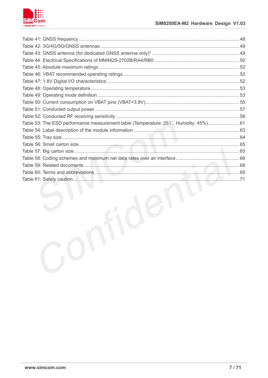
Table 41: GNSS frequency ......................................................................................................................... 48
Table 42: 3G/4G/5G/GNSS antennas ......................................................................................................... 49
Table 43: GNSS antenna (for dedicated GNSS antenna only)* .................................................................. 49
Table 44: Electrical Specifications of MM4829-2702B/RA4/RB0 ................................................................ 50
Table 45: Absolute maximum ratings .......................................................................................................... 52
Table 46: VBAT recommended operating ratings ........................................................................................ 52
Table 47: 1.8V Digital I/O characteristics .................................................................................................... 52
Table 48: Operating temperature ................................................................................................................ 53
Table 49: Operating mode definition ........................................................................................................... 53
Table 50: Current consumption on VBAT pins (VBAT=3.8V) ....................................................................... 55
Table 51: Conducted output power ............................................................................................................. 57
Table 52: Conducted RF receiving sensitivity ............................................................................................. 58
Table 53: The ESD performance measurement table (Temperature: 25℃, Humidity: 45%) ....................... 61
Table 54: Label description of the module information ................................................................................ 63
Table 55: Tray size ...................................................................................................................................... 64
Table 56: Small carton size ......................................................................................................................... 65
Table 57: Big carton size ............................................................................................................................. 65
Table 58: Coding schemes and maximum net data rates over air interface ................................................ 66
Table 59: Related documents ..................................................................................................................... 68
Table 60: Terms and abbreviations ............................................................................................................. 69
Table 61: Safety caution.............................................................................................................................. 71
www.simcom.com 7 / 71
�
SIM8200EA-M2 Hardware Design V1.03
Figure Index
Figure 1: Block diagram .............................................................................................................................. 10
Figure 2: Pin assignment ............................................................................................................................ 13
Figure 3: Dimensions of the module (unit: mm) .......................................................................................... 18
Figure 4: VBAT voltage drop at the maximum power radio transmission .................................................... 19
Figure 5: Power supply application circuit ................................................................................................... 20
Figure 6: Linear regulator reference circuit ................................................................................................. 21
Figure 7: Switching mode power supply reference circuit ........................................................................... 22
Figure 8: Reference power on/off circuit ..................................................................................................... 23
Figure 9: Power on sequence ..................................................................................................................... 23
Figure 10: Power off sequence ................................................................................................................... 24
Figure 11: Reference reset circuit ............................................................................................................... 25
Figure 12: The reset timing sequence of the module .................................................................................. 26
Figure 13: I2C reference circuit ................................................................................................................... 27
Figure 14: WoWWAN# signal level at SMS and URC report ...................................................................... 28
Figure 15: WoWWAN# reference circuit ..................................................................................................... 28
Figure 16: USB reference circuit ................................................................................................................. 29
Figure 17: PCIe interface reference circuit (EP Mode) ................................................................................ 31
Figure 18: (U)SIM interface reference circuit .............................................................................................. 34
Figure 19: I2S timing ................................................................................................................................... 36
Figure 20: Audio codec reference circuit ..................................................................................................... 37
Figure 21: LED1# reference circuit ............................................................................................................. 40
Figure 22: W_DISABLE1# pin reference circuit .......................................................................................... 42
Figure 23: W_DISABLE2# pin reference circuit .......................................................................................... 43
Figure 24: Antenna interfaces ..................................................................................................................... 45
Figure 25: 3D view of MM4829-2702B/ RA4/ RBO ..................................................................................... 50
Figure 26: 3D view of MXHJD3HJ1000 ...................................................................................................... 51
Figure 27: Thermal dissipation area on bottom side of the module ............................................................ 60
Figure 28: Top and bottom view of the module ........................................................................................... 62
Figure 29: Label description of the module ................................................................................................. 63
Figure 30: Packaging procedures ............................................................................................................... 64
Figure 31: Tray view of the module ............................................................................................................. 64
Figure 32: Small carton view ....................................................................................................................... 65
Figure 33: Big carton view .......................................................................................................................... 65
www.simcom.com 8 / 71
�




 V2版本原理图(Capacitive-Fingerprint-Reader-Schematic_V2).pdf
 摄像头工作原理.doc
 VL53L0X简要说明(En.FLVL53L00216).pdf
 原理图(DVK720-Schematic).pdf
 原理图(Pico-Clock-Green-Schdoc).pdf
 原理图(RS485-CAN-HAT-B-schematic).pdf
 File:SIM7500_SIM7600_SIM7800 Series_SSL_Application Note_V2.00.pdf
 ADS1263(Ads1262).pdf
 原理图(Open429Z-D-Schematic).pdf
 用户手册(Capacitive_Fingerprint_Reader_User_Manual_CN).pdf
 CY7C68013A(英文版)(CY7C68013A).pdf
 TechnicalReference_Dem.pdf