CC1101
CC1101
Low-Cost Low-Power Sub-1GHz RF Transceiver
(Enhanced CC1100 )
Applications
• Ultra
operating
ISM/SRD bands
low-power wireless applications
the 315/433/868/915 MHz
in
• Wireless alarm and security systems
•
Industrial monitoring and control
is a
for very
Product Description
low-cost sub- 1 GHz
The CC1101
transceiver designed
low-power
wireless applications. The circuit is mainly
intended for the ISM (Industrial, Scientific and
Medical) and SRD (Short Range Device)
frequency bands at 315, 433, 868, and 915
MHz, but can easily be programmed for
operation at other frequencies in the 300-348
MHz, 387-464 MHz and 779-928 MHz bands.
CC1101 is an improved and code compatible
version of the CC1100 RF transceiver. The
main improvements on the CC1101 include:
Improved spurious response
•
• Better close-in phase noise improving
(ACP)
Adjacent Channel Power
performance
• Higher input saturation level
•
• Extended frequency bands of
Improved output power ramping
operation, i.e.
CC1100: 400-464 MHz and 800-928
MHz
CC1101: 387-464 MHz and 779-928
MHz
• Wireless sensor networks
• AMR – Automatic Meter Reading
• Home and building automation
The RF transceiver is integrated with a highly
configurable baseband modem. The modem
supports various modulation formats and has
a configurable data rate up to 500 kBaud.
CC1101 provides extensive hardware support
for packet handling, data buffering, burst
transmissions, clear channel assessment, link
quality indication, and wake-on-radio.
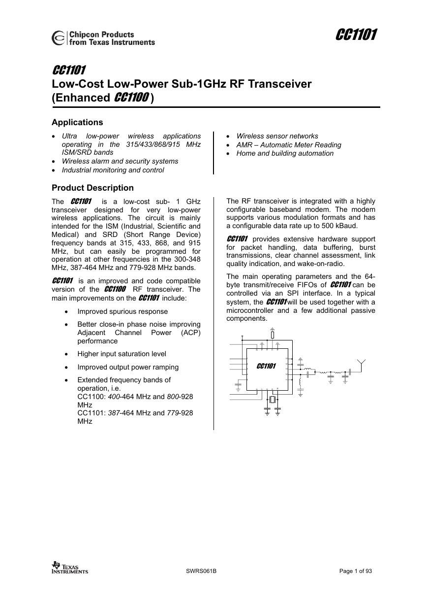
The main operating parameters and the 64-
byte transmit/receive FIFOs of CC1101 can be
controlled via an SPI interface. In a typical
system, the CC1101 will be used together with a
microcontroller and a few additional passive
components.
1
2
3
4
5
0
2
9
1
8
1
7
1
6
1
CC1101
0
6 7 8 9 1
15
14
13
12
11
SWRS061B
Page 1 of 93
�
CC1101
Key Features
RF Performance
• High sensitivity (–111 dBm at 1.2 kBaud,
868 MHz, 1% packet error rate)
• Low current consumption (14.7 mA in RX,
1.2 kBaud, 868 MHz)
• Programmable output power up to +10
dBm for all supported frequencies
• Excellent receiver selectivity and blocking
• Programmable data rate from 1.2 to 500
performance
kBaud
• Frequency bands: 300-348 MHz, 387-464
MHz and 779-928 MHz
Analog Features
• 2-FSK, GFSK, and MSK supported as well
as OOK and flexible ASK shaping
• Suitable for frequency hopping systems
frequency
due
settling
synthesizer: 90us settling time
to a
fast
• Automatic
Frequency Compensation
(AFC) can be used to align the frequency
synthesizer
received center
frequency
Integrated analog temperature sensor
the
to
•
Digital Features
• Flexible support
for packet oriented
systems: On-chip support for sync word
detection, address check, flexible packet
length, and automatic CRC handling
• Efficient SPI interface: All registers can be
programmed with one “burst” transfer
• Digital RSSI output
• Programmable channel filter bandwidth
• Programmable Carrier Sense
(CS)
indicator
• Programmable Preamble Quality Indicator
(PQI) for improved protection against false
sync word detection in random noise
• Support
for automatic Clear Channel
Assessment (CCA) before transmitting (for
listen-before-talk systems)
• Support
for per-package Link Quality
• Optional automatic whitening and de-
Indication (LQI)
whitening of data
Low-Power Features
• 400 nA sleep mode current consumption
• Fast startup time: 240us from sleep to RX
or TX mode (measured on EM reference
design [5] and [6])
• Wake-on-radio functionality for automatic
low-power RX polling
• Separate 64-byte RX and TX data FIFOs
(enables burst mode data transmission)
General
• Few external components: Completely on-
chip frequency synthesizer, no external
filters or RF switch needed
• Green package: RoHS compliant and no
antimony or bromine
• Small size (QLP 4x4 mm package, 20
pins)
• Suited for systems targeting compliance
with EN 300 220 (Europe) and FCC CFR
Part 15 (US).
• Support
for
asynchronous
and
synchronous serial receive/transmit mode
for backwards compatibility with existing
radio communication protocols
SWRS061B
Page 2 of 93
�
CC1101
Abbreviations
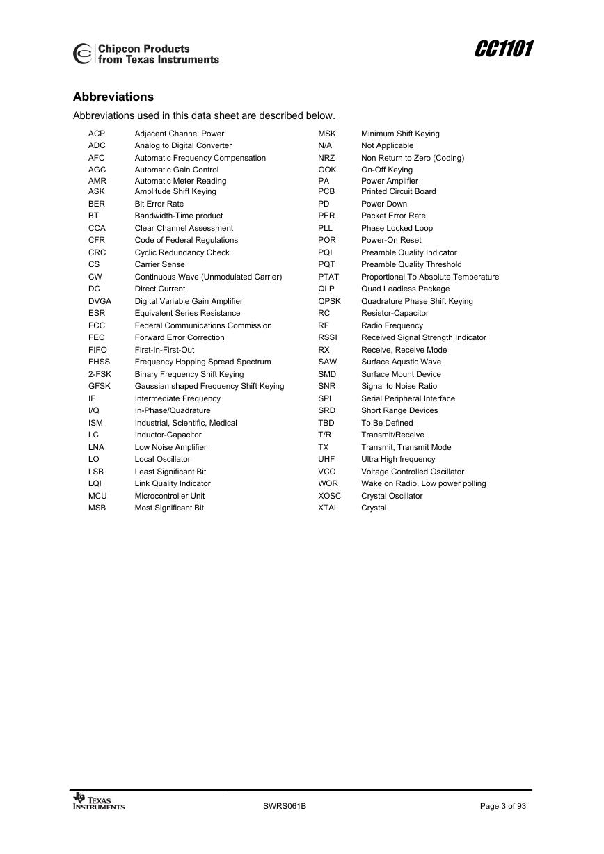
Abbreviations used in this data sheet are described below.
MSK
N/A
NRZ
OOK
PA
PCB
PD
PER
PLL
POR
PQI
PQT
PTAT
QLP
QPSK
RC
RF
RSSI
RX
SAW
SMD
SNR
SPI
SRD
TBD
T/R
TX
UHF
VCO
WOR
XOSC
XTAL
Adjacent Channel Power
Analog to Digital Converter
Automatic Frequency Compensation
Automatic Gain Control
Automatic Meter Reading
Amplitude Shift Keying
Bit Error Rate
Bandwidth-Time product
Clear Channel Assessment
Code of Federal Regulations
Cyclic Redundancy Check
Carrier Sense
Continuous Wave (Unmodulated Carrier)
Direct Current
Digital Variable Gain Amplifier
Equivalent Series Resistance
Federal Communications Commission
Forward Error Correction
First-In-First-Out
Frequency Hopping Spread Spectrum
Binary Frequency Shift Keying
Gaussian shaped Frequency Shift Keying
Intermediate Frequency
In-Phase/Quadrature
Industrial, Scientific, Medical
Inductor-Capacitor
Low Noise Amplifier
Local Oscillator
Least Significant Bit
Link Quality Indicator
Microcontroller Unit
Most Significant Bit
ACP
ADC
AFC
AGC
AMR
ASK
BER
BT
CCA
CFR
CRC
CS
CW
DC
DVGA
ESR
FCC
FEC
FIFO
FHSS
2-FSK
GFSK
IF
I/Q
ISM
LC
LNA
LO
LSB
LQI
MCU
MSB
Minimum Shift Keying
Not Applicable
Non Return to Zero (Coding)
On-Off Keying
Power Amplifier
Printed Circuit Board
Power Down
Packet Error Rate
Phase Locked Loop
Power-On Reset
Preamble Quality Indicator
Preamble Quality Threshold
Proportional To Absolute Temperature
Quad Leadless Package
Quadrature Phase Shift Keying
Resistor-Capacitor
Radio Frequency
Received Signal Strength Indicator
Receive, Receive Mode
Surface Aqustic Wave
Surface Mount Device
Signal to Noise Ratio
Serial Peripheral Interface
Short Range Devices
To Be Defined
Transmit/Receive
Transmit, Transmit Mode
Ultra High frequency
Voltage Controlled Oscillator
Wake on Radio, Low power polling
Crystal Oscillator
Crystal
SWRS061B
Page 3 of 93
�
CC1101
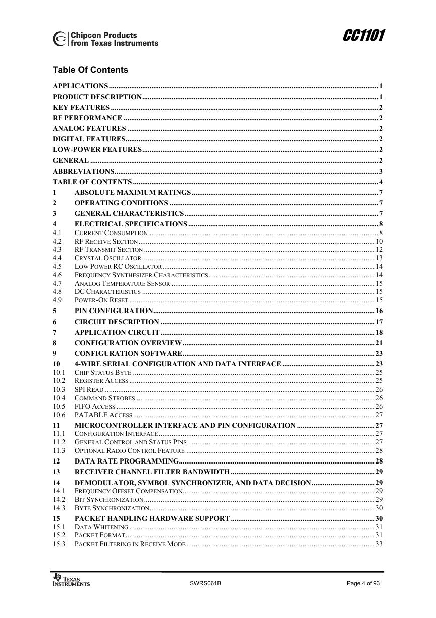
Table Of Contents
APPLICATIONS..................................................................................................................................................1
PRODUCT DESCRIPTION................................................................................................................................1
KEY FEATURES .................................................................................................................................................2
RF PERFORMANCE ..........................................................................................................................................2
ANALOG FEATURES ........................................................................................................................................2
DIGITAL FEATURES.........................................................................................................................................2
LOW-POWER FEATURES................................................................................................................................2
GENERAL ............................................................................................................................................................2
ABBREVIATIONS...............................................................................................................................................3
TABLE OF CONTENTS .....................................................................................................................................4
ABSOLUTE MAXIMUM RATINGS.....................................................................................................7
1
2
OPERATING CONDITIONS .................................................................................................................7
GENERAL CHARACTERISTICS.........................................................................................................7
3
ELECTRICAL SPECIFICATIONS.......................................................................................................8
4
4.1
CURRENT CONSUMPTION ............................................................................................................................8
4.2
RF RECEIVE SECTION................................................................................................................................10
RF TRANSMIT SECTION .............................................................................................................................12
4.3
CRYSTAL OSCILLATOR..............................................................................................................................13
4.4
4.5
LOW POWER RC OSCILLATOR...................................................................................................................14
4.6
FREQUENCY SYNTHESIZER CHARACTERISTICS..........................................................................................14
ANALOG TEMPERATURE SENSOR ..............................................................................................................15
4.7
4.8
DC CHARACTERISTICS ..............................................................................................................................15
POWER-ON RESET.....................................................................................................................................15
4.9
5
PIN CONFIGURATION........................................................................................................................16
CIRCUIT DESCRIPTION ....................................................................................................................17
6
APPLICATION CIRCUIT....................................................................................................................18
7
CONFIGURATION OVERVIEW........................................................................................................21
8
9
CONFIGURATION SOFTWARE........................................................................................................23
10
4-WIRE SERIAL CONFIGURATION AND DATA INTERFACE ..................................................23
10.1 CHIP STATUS BYTE ...................................................................................................................................25
10.2 REGISTER ACCESS.....................................................................................................................................25
10.3 SPI READ ..................................................................................................................................................26
10.4 COMMAND STROBES .................................................................................................................................26
10.5 FIFO ACCESS ............................................................................................................................................26
10.6 PATABLE ACCESS...................................................................................................................................27
11 MICROCONTROLLER INTERFACE AND PIN CONFIGURATION ..........................................27
11.1 CONFIGURATION INTERFACE.....................................................................................................................27
11.2 GENERAL CONTROL AND STATUS PINS .....................................................................................................27
11.3 OPTIONAL RADIO CONTROL FEATURE ......................................................................................................28
12
DATA RATE PROGRAMMING..........................................................................................................28
RECEIVER CHANNEL FILTER BANDWIDTH ..............................................................................29
13
14
DEMODULATOR, SYMBOL SYNCHRONIZER, AND DATA DECISION..................................29
14.1 FREQUENCY OFFSET COMPENSATION........................................................................................................29
14.2 BIT SYNCHRONIZATION.............................................................................................................................29
14.3 BYTE SYNCHRONIZATION..........................................................................................................................30
15
PACKET HANDLING HARDWARE SUPPORT ..............................................................................30
15.1 DATA WHITENING.....................................................................................................................................31
15.2 PACKET FORMAT.......................................................................................................................................31
15.3 PACKET FILTERING IN RECEIVE MODE......................................................................................................33
SWRS061B
Page 4 of 93
�
CC1101
15.4 PACKET HANDLING IN TRANSMIT MODE...................................................................................................33
15.5 PACKET HANDLING IN RECEIVE MODE .....................................................................................................34
15.6 PACKET HANDLING IN FIRMWARE.............................................................................................................34
16 MODULATION FORMATS.................................................................................................................35
16.1 FREQUENCY SHIFT KEYING.......................................................................................................................35
16.2 MINIMUM SHIFT KEYING...........................................................................................................................35
16.3 AMPLITUDE MODULATION ........................................................................................................................35
17
RECEIVED SIGNAL QUALIFIERS AND LINK QUALITY INFORMATION ............................36
17.1 SYNC WORD QUALIFIER............................................................................................................................36
17.2 PREAMBLE QUALITY THRESHOLD (PQT) ..................................................................................................36
17.3 RSSI..........................................................................................................................................................36
17.4 CARRIER SENSE (CS).................................................................................................................................38
17.5 CLEAR CHANNEL ASSESSMENT (CCA) .....................................................................................................39
17.6 LINK QUALITY INDICATOR (LQI)..............................................................................................................39
18
FORWARD ERROR CORRECTION WITH INTERLEAVING .....................................................39
18.1 FORWARD ERROR CORRECTION (FEC)......................................................................................................39
INTERLEAVING ..........................................................................................................................................40
18.2
19
RADIO CONTROL................................................................................................................................41
19.1 POWER-ON START-UP SEQUENCE.............................................................................................................41
19.2 CRYSTAL CONTROL...................................................................................................................................42
19.3 VOLTAGE REGULATOR CONTROL..............................................................................................................43
19.4 ACTIVE MODES .........................................................................................................................................43
19.5 WAKE ON RADIO (WOR)..........................................................................................................................43
19.6 TIMING ......................................................................................................................................................44
19.7 RX TERMINATION TIMER ..........................................................................................................................45
DATA FIFO ............................................................................................................................................45
20
FREQUENCY PROGRAMMING........................................................................................................47
21
22
VCO .........................................................................................................................................................47
22.1 VCO AND PLL SELF-CALIBRATION ..........................................................................................................47
VOLTAGE REGULATORS .................................................................................................................48
23
OUTPUT POWER PROGRAMMING ................................................................................................48
24
25
SHAPING AND PA RAMPING............................................................................................................49
SELECTIVITY.......................................................................................................................................51
26
27
CRYSTAL OSCILLATOR....................................................................................................................52
27.1 REFERENCE SIGNAL ..................................................................................................................................53
28
EXTERNAL RF MATCH .....................................................................................................................53
PCB LAYOUT RECOMMENDATIONS.............................................................................................53
29
30
GENERAL PURPOSE / TEST OUTPUT CONTROL PINS.............................................................54
31
ASYNCHRONOUS AND SYNCHRONOUS SERIAL OPERATION ..............................................56
31.1 ASYNCHRONOUS OPERATION ....................................................................................................................56
31.2 SYNCHRONOUS SERIAL OPERATION ..........................................................................................................56
32
SYSTEM CONSIDERATIONS AND GUIDELINES.........................................................................56
32.1 SRD REGULATIONS...................................................................................................................................56
32.2 FREQUENCY HOPPING AND MULTI-CHANNEL SYSTEMS............................................................................57
32.3 WIDEBAND MODULATION NOT USING SPREAD SPECTRUM........................................................................57
32.4 DATA BURST TRANSMISSIONS...................................................................................................................57
32.5 CONTINUOUS TRANSMISSIONS ..................................................................................................................58
32.6 CRYSTAL DRIFT COMPENSATION ..............................................................................................................58
32.7 SPECTRUM EFFICIENT MODULATION.........................................................................................................58
32.8 LOW COST SYSTEMS .................................................................................................................................58
32.9 BATTERY OPERATED SYSTEMS .................................................................................................................58
32.10
INCREASING OUTPUT POWER ................................................................................................................58
SWRS061B
Page 5 of 93
�
CC1101
33
CONFIGURATION REGISTERS........................................................................................................59
33.1 CONFIGURATION REGISTER DETAILS – REGISTERS WITH PRESERVED VALUES IN SLEEP STATE...............63
33.2 CONFIGURATION REGISTER DETAILS – REGISTERS THAT LOOSE PROGRAMMING IN SLEEP STATE .........83
33.3 STATUS REGISTER DETAILS.......................................................................................................................84
34
PACKAGE DESCRIPTION (QLP 20).................................................................................................87
34.1 RECOMMENDED PCB LAYOUT FOR PACKAGE (QLP 20) ...........................................................................88
34.2 PACKAGE THERMAL PROPERTIES ..............................................................................................................88
34.3 SOLDERING INFORMATION ........................................................................................................................88
34.4 TRAY SPECIFICATION ................................................................................................................................88
34.5 CARRIER TAPE AND REEL SPECIFICATION.................................................................................................89
ORDERING INFORMATION..............................................................................................................89
35
36
REFERENCES .......................................................................................................................................90
37
GENERAL INFORMATION................................................................................................................91
37.1 DOCUMENT HISTORY ................................................................................................................................91
37.2 PRODUCT STATUS DEFINITIONS ................................................................................................................91
38
ADDRESS INFORMATION.................................................................................................................92
39
TI WORLDWIDE TECHNICAL SUPPORT......................................................................................92
SWRS061B
Page 6 of 93
�
CC1101
1
Absolute Maximum Ratings
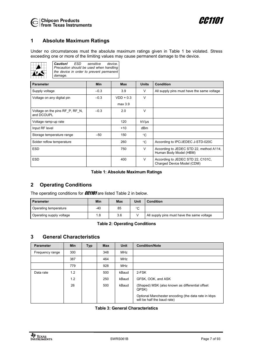
Under no circumstances must the absolute maximum ratings given in Table 1 be violated. Stress
exceeding one or more of the limiting values may cause permanent damage to the device.
ESD
sensitive
Caution!
device.
Precaution should be used when handling
the device in order to prevent permanent
damage.
Parameter
Supply voltage
Voltage on any digital pin
Voltage on the pins RF_P, RF_N,
and DCOUPL
Voltage ramp-up rate
Input RF level
Storage temperature range
Solder reflow temperature
ESD
ESD
Min
–0.3
–0.3
–0.3
–50
Max
3.9
VDD + 0.3
max 3.9
2.0
120
+10
150
260
750
400
Units
V
V
V
kV/µs
dBm
°C
°C
V
V
Condition
All supply pins must have the same voltage
According to IPC/JEDEC J-STD-020C
According to JEDEC STD 22, method A114,
Human Body Model (HBM)
According to JEDEC STD 22, C101C,
Charged Device Model (CDM)
Table 1: Absolute Maximum Ratings
2 Operating Conditions
The operating conditions for CC1101 are listed Table 2 in below.
Parameter
Operating temperature
Operating supply voltage
Min
-40
1.8
Max
85
3.6
Unit
°C
V
Condition
All supply pins must have the same voltage
Table 2: Operating Conditions
3 General Characteristics
Parameter
Frequency range
Data rate
Min
300
387
779
1.2
1.2
26
Typ
Max
348
464
928
500
250
500
Unit
MHz
MHz
MHz
kBaud
kBaud
kBaud
Condition/Note
2-FSK
GFSK, OOK, and ASK
(Shaped) MSK (also known as differential offset
QPSK)
Optional Manchester encoding (the data rate in kbps
will be half the baud rate)
Table 3: General Characteristics
SWRS061B
Page 7 of 93
�
CC1101
4
Electrical Specifications
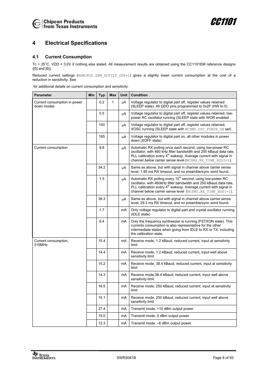
4.1 Current Consumption
Tc = 25°C, VDD = 3.0V if nothing else stated. All measurement results are obtained using the CC1101EM reference designs
([5] and [6]).
Reduced current settings (MDMCFG2.DEM_DCFILT_OFF=1) gives a slightly lower current consumption at the cost of a
reduction in sensitivity. See
for additional details on current consumption and sensitivity.
Parameter
Current consumption in power
down modes
Current consumption
Current consumption,
315MHz
Min Typ Max Unit Condition
0.2
1
µA Voltage regulator to digital part off, register values retained
(SLEEP state). All GDO pins programmed to 0x2F (HW to 0)
0.5
100
165
9.8
34.2
1.5
39.3
1.7
8.4
15.4
14.4
15.2
14.3
16.5
15.1
27.4
15.0
12.3
µA Voltage regulator to digital part off, register values retained, low-
power RC oscillator running (SLEEP state with WOR enabled
µA Voltage regulator to digital part off, register values retained,
XOSC running (SLEEP state with MCSM0.OSC_FORCE_ON set)
µA Voltage regulator to digital part on, all other modules in power
down (XOFF state)
µA Automatic RX polling once each second, using low-power RC
oscillator, with 460 kHz filter bandwidth and 250 kBaud data rate,
PLL calibration every 4th wakeup. Average current with signal in
channel below carrier sense level (MCSM2.RX_TIME_RSSI=1).
µA Same as above, but with signal in channel above carrier sense
level, 1.95 ms RX timeout, and no preamble/sync word found.
µA Automatic RX polling every 15th second, using low-power RC
oscillator, with 460kHz filter bandwidth and 250 kBaud data rate,
PLL calibration every 4th wakeup. Average current with signal in
channel below carrier sense level (MCSM2.RX_TIME_RSSI=1).
µA Same as above, but with signal in channel above carrier sense
level, 29.3 ms RX timeout, and no preamble/sync word found.
mA Only voltage regulator to digital part and crystal oscillator running
(IDLE state)
mA Only the frequency synthesizer is running (FSTXON state). This
currents consumption is also representative for the other
intermediate states when going from IDLE to RX or TX, including
the calibration state.
mA Receive mode, 1.2 kBaud, reduced current, input at sensitivity
limit
mA Receive mode, 1.2 kBaud, reduced current, input well above
sensitivity limit
mA Receive mode, 38.4 kBaud, reduced current, input at sensitivity
limit
mA Receive mode,38.4 kBaud, reduced current, input well above
sensitivity limit
mA Receive mode, 250 kBaud, reduced current, input at sensitivity
limit
mA Receive mode, 250 kBaud, reduced current, input well above
sensitivity limit
mA Transmit mode, +10 dBm output power
mA Transmit mode, 0 dBm output power
mA Transmit mode, –6 dBm output power
SWRS061B
Page 8 of 93
�





 V2版本原理图(Capacitive-Fingerprint-Reader-Schematic_V2).pdf
 摄像头工作原理.doc
 VL53L0X简要说明(En.FLVL53L00216).pdf
 原理图(DVK720-Schematic).pdf
 原理图(Pico-Clock-Green-Schdoc).pdf
 原理图(RS485-CAN-HAT-B-schematic).pdf
 File:SIM7500_SIM7600_SIM7800 Series_SSL_Application Note_V2.00.pdf
 ADS1263(Ads1262).pdf
 原理图(Open429Z-D-Schematic).pdf
 用户手册(Capacitive_Fingerprint_Reader_User_Manual_CN).pdf
 CY7C68013A(英文版)(CY7C68013A).pdf
 TechnicalReference_Dem.pdf