PL-2303 Edition
USB to Serial Bridge Controller
Product Datasheet
Document Revision: 1.6
Document Release: April 26, 2005
Prolific Technology Inc.
7F, No. 48, Sec. 3, Nan Kang Rd.
Nan Kang, Taipei 115, Taiwan, R.O.C.
Telephone: +886-2-2654-6363
Fax: +886-2-2654-6161
E-mail: sales@prolific.com.tw
Website: http://www.prolific.com.tw
�
Revised Date:
April 26, 2005
ds_pl2303_v16.doc
Disclaimer
All the information in this document is subject to change without prior notice. Prolific Technology Inc.
does not make any representations or any warranties (implied or otherwise) regarding the accuracy
and completeness of this document and shall in no event be liable for any loss of profit or any other
commercial damage, including but not limited to special, incidental, consequential, or other damages.
Trademarks
The Prolific logo is a registered trademark of Prolific Technology Inc. All brand names and product
names used in this document are trademarks or registered trademarks of their respective holders.
Copyrights
Copyright © 2005 Prolific Technology Inc. All rights reserved.
No part of this document may be reproduced or transmitted in any form by any means without the
express written permission of Prolific Technology Inc.
PL-2303 Product Datasheet
- 2 -
Document Version 1.6
�
Revision History
Revision
Description
1.6
Modify Temperature Characteristics (Sec 8.4)
Added List of Figures and List of Tables
Modify Features section
Improve clarity of Pin Assignment diagram
Correct Minimum Operating Temperature to 0oC
Modify Operating Voltage
Add EEPROM Timing Diagram
Add Reset Timing Diagram
Added Ordering Information
Added Reel Packing Information
Add Windows CE .NET support feature
Buffer for upstream and downstream data flow – change
from 96 to 256 bytes
For Chip Version H (date code 0206)
Add OS Support in Features Section
Correct default values in Table 5. Device Configuration
Register
Add Suspend Current in DC Characteristics Section
Move Operating Temperature in DC Characteristics to new
section
1.5
1.4
1.3
1.2
Revised Date:
April 26, 2005
ds_pl2303_v16.doc
Date
April 26, 2005
February 02, 2005
August 29, 2002
August 01, 2002
July 03, 2002
PL-2303 Product Datasheet
- 3 -
Document Version 1.6
�
Revised Date:
April 26, 2005
ds_pl2303_v16.doc
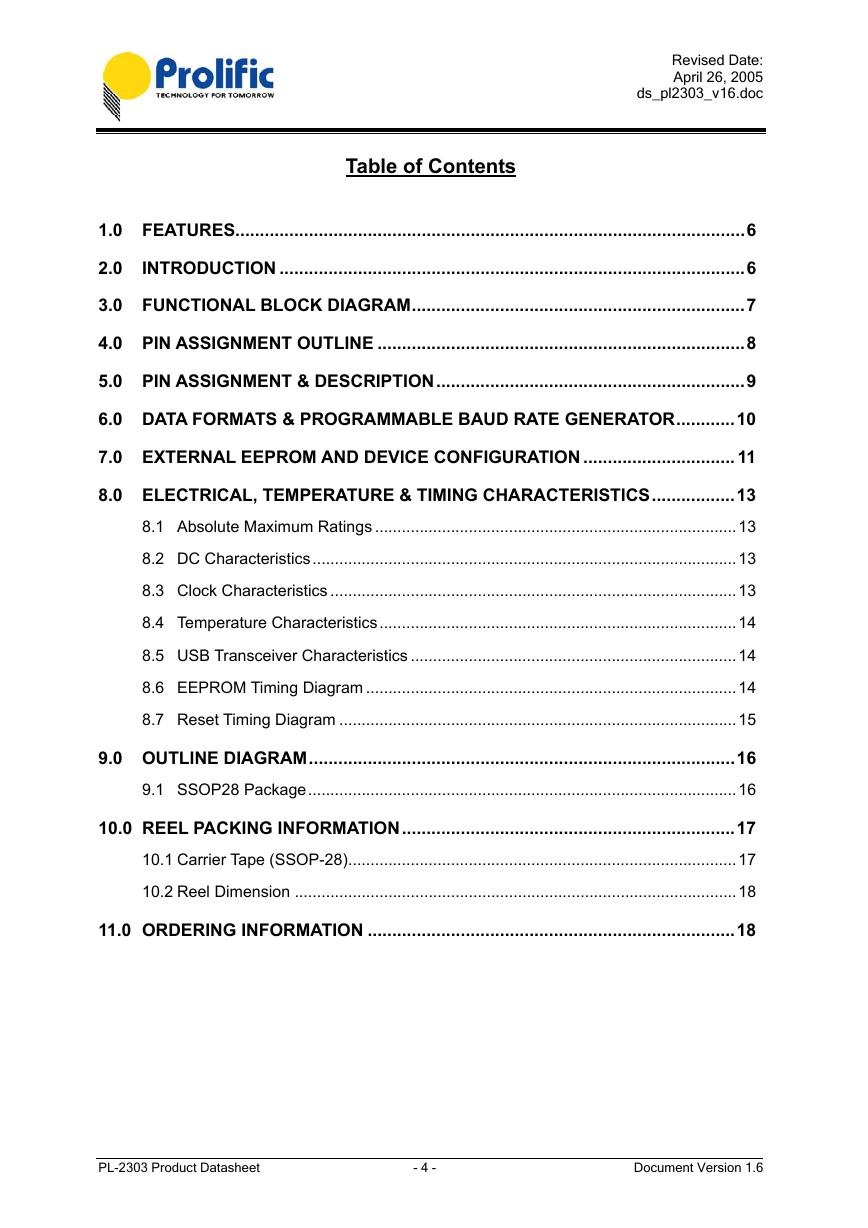
Table of Contents
1.0 FEATURES........................................................................................................6
2.0
INTRODUCTION ...............................................................................................6
3.0 FUNCTIONAL BLOCK DIAGRAM....................................................................7
4.0 PIN ASSIGNMENT OUTLINE ...........................................................................8
5.0 PIN ASSIGNMENT & DESCRIPTION...............................................................9
6.0 DATA FORMATS & PROGRAMMABLE BAUD RATE GENERATOR............10
7.0 EXTERNAL EEPROM AND DEVICE CONFIGURATION ............................... 11
8.0 ELECTRICAL, TEMPERATURE & TIMING CHARACTERISTICS.................13
8.1 Absolute Maximum Ratings .................................................................................13
8.2 DC Characteristics...............................................................................................13
8.3 Clock Characteristics ...........................................................................................13
8.4 Temperature Characteristics................................................................................14
8.5 USB Transceiver Characteristics .........................................................................14
8.6 EEPROM Timing Diagram ...................................................................................14
8.7 Reset Timing Diagram .........................................................................................15
9.0 OUTLINE DIAGRAM.......................................................................................16
9.1 SSOP28 Package................................................................................................16
10.0 REEL PACKING INFORMATION....................................................................17
10.1 Carrier Tape (SSOP-28).......................................................................................17
10.2 Reel Dimension ...................................................................................................18
11.0 ORDERING INFORMATION ...........................................................................18
PL-2303 Product Datasheet
- 4 -
Document Version 1.6
�
Revised Date:
April 26, 2005
ds_pl2303_v16.doc
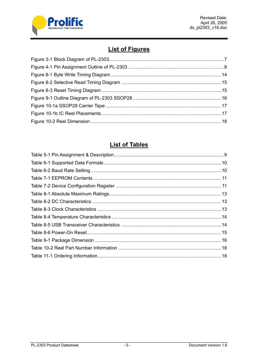
List of Figures
Figure 3-1 Block Diagram of PL-2303.......................................................................................7
Figure 4-1 Pin Assignment Outline of PL-2303.........................................................................8
Figure 8-1 Byte Write Timing Diagram....................................................................................14
Figure 8-2 Selective Read Timing Diagram ............................................................................15
Figure 8-3 Reset Timing Diagram ...........................................................................................15
Figure 9-1 Outline Diagram of PL-2303 SSOP28 ...................................................................16
Figure 10-1a SSOP28 Carrier Tape........................................................................................17
Figure 10-1b IC Reel Placements...........................................................................................17
Figure 10-2 Reel Dimension ...................................................................................................18
List of Tables
Table 5-1 Pin Assignment & Description ...................................................................................9
Table 6-1 Supported Data Formats.........................................................................................10
Table 6-2 Baud Rate Setting ...................................................................................................10
Table 7-1 EEPROM Contents ................................................................................................. 11
Table 7-2 Device Configuration Register ................................................................................ 11
Table 8-1 Absolute Maximum Ratings.....................................................................................13
Table 8-2 DC Characteristics ..................................................................................................13
Table 8-3 Clock Characteristics ..............................................................................................13
Table 8-4 Temperature Characteristics ...................................................................................14
Table 8-5 USB Transceiver Characteristics ............................................................................14
Table 8-6 Power-On Reset......................................................................................................15
Table 9-1 Package Dimension ................................................................................................16
Table 10-2 Reel Part Number Information ..............................................................................18
Table 11-1 Ordering Information..............................................................................................18
PL-2303 Product Datasheet
- 5 -
Document Version 1.6
�
1.0 Features
Revised Date:
April 26, 2005
ds_pl2303_v16.doc
Fully compliant with USB Specification v1.1 and USB CDC v1.1
Supports RS232 Serial interface
Supports automatic handshake mode
Supports Remote wake-up and power management
256-bytes buffer each for upstream and downstream data flow
Supports default ROM or external EEPROM for device configuration
On-chip USB transceiver
On-chip crystal oscillator running at 12MHz
Supports Windows 98/SE, ME, 2000, XP, Windows CE3.0, CE .NET, Linux, and Mac OS
Designed for Windows XP/2000 Certified Logo Drivers
USB-IF Logo Compliant with TID 10240590
28-Pin SSOP package
2.0 Introduction
The PL-2303 operates as a bridge between one USB port and one standard RS232 Serial port. The
two large on-chip buffers accommodate data flow from two different buses. The USB bulk-type data is
adopted for maximum data transfer. Automatic handshake is supported at the Serial port. With these, a
much higher baud rate can be achieved compared to the legacy UART controller.
This device is also compliant with USB power management and remote wakeup scheme. Only
minimum power is consumed from the host during Suspend. By integrating all the function in a
SSOP-28 package, this chip is suitable for cable embedding. Users just simply hook the cable into PC
or hub’s USB port, and then they can connect to any RS-232 devices.
PL-2303 Product Datasheet
- 6 -
Document Version 1.6
�
3.0 Functional Block Diagram
USB Port
Revised Date:
April 26, 2005
ds_pl2303_v16.doc
USB
Transceiver
USB
SIE
Control
Unit
DOWN
STREAM
BUFFER
CLOCK
SYNTHESIZER
OSCILLATOR
RS-232 SERIAL
INTERFACE
REGISTER/
CONFIG/
STATUS/
CONTROL
UP
STREAM
BUFFER
EEPROM
INTERFACE
Serial Port
I2C Bus
Figure 3-1 Block Diagram of PL-2303
PL-2303 Product Datasheet
- 7 -
Document Version 1.6
�
4.0 Pin Assignment Outline
Revised Date:
April 26, 2005
ds_pl2303_v16.doc
SSOP 28 PACKAGE
(TOP VIEW)
TXD
DTR_N
RTS_N
VDD_232
RXD
RI_N
GND
VDD
DSR_N
DCD_N
CTS_N
SHTD_N
EE_CLK
EE_DATA
1
2
3
4
5
6
7
8
9
10
11
12
13
14
28
27
26
25
24
23
22
21
20
19
18
17
16
OSC2
OSC1
PLL_TEST
GND_PLL
VDD_PLL
LD_MODE
TRI_MODE
GND
VDD
RESET
GND_3V3
VDD_3V3
DM
15
DP
Figure 4-1 Pin Assignment Outline of PL-2303
PL-2303 Product Datasheet
- 8 -
Document Version 1.6
�



 V2版本原理图(Capacitive-Fingerprint-Reader-Schematic_V2).pdf
 摄像头工作原理.doc
 VL53L0X简要说明(En.FLVL53L00216).pdf
 原理图(DVK720-Schematic).pdf
 原理图(Pico-Clock-Green-Schdoc).pdf
 原理图(RS485-CAN-HAT-B-schematic).pdf
 File:SIM7500_SIM7600_SIM7800 Series_SSL_Application Note_V2.00.pdf
 ADS1263(Ads1262).pdf
 原理图(Open429Z-D-Schematic).pdf
 用户手册(Capacitive_Fingerprint_Reader_User_Manual_CN).pdf
 CY7C68013A(英文版)(CY7C68013A).pdf
 TechnicalReference_Dem.pdf