Table of Content
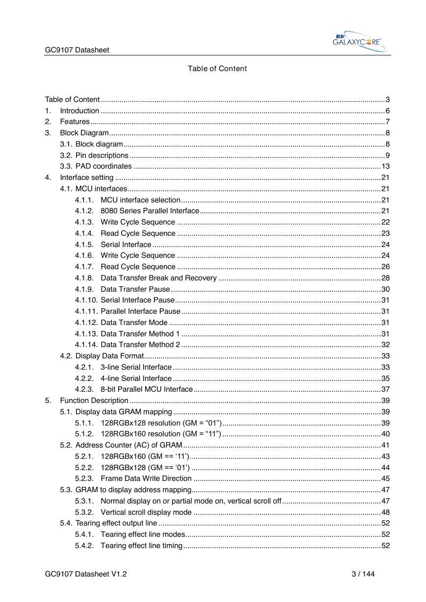
1. Introduction
2. Features
3. Block Diagram
3.1. Block diagram
3.2. Pin descriptions
3.3. PAD coordinates
4. Interface setting
4.1. MCU interfaces
4.1.1. MCU interface selection
4.1.2. 8080 Series Parallel Interface
4.1.3. Write Cycle Sequence
4.1.4. Read Cycle Sequence
4.1.5. Serial Interface
4.1.6. Write Cycle Sequence
4.1.7. Read Cycle Sequence
4.1.8. Data Transfer Break and Recovery
4.1.9. Data Transfer Pause
4.1.10. Serial Interface Pause
4.1.11. Parallel Interface Pause
4.1.12. Data Transfer Mode
4.1.13. Data Transfer Method 1
4.1.14. Data Transfer Method 2
4.2. Display Data Format
4.2.1. 3-line Serial Interface
4.2.2. 4-line Serial Interface
4.2.3. 8-bit Parallel MCU Interface
5. Function Description
5.1. Display data GRAM mapping
5.1.1. 128RGBx128 resolution (GM = “01”)
5.1.2. 128RGBx160 resolution (GM = “11”)
5.2. Address Counter (AC) of GRAM
5.2.1. 128RGBx160 (GM == ‘11’)
5.2.2. 128RGBx128 (GM == ‘01’)
5.2.3. Frame Data Write Direction
5.3. GRAM to display address mapping
5.3.1. Normal display on or partial mode on, vertical scroll off
5.3.2. Vertical scroll display mode
5.4. Tearing effect output line
5.4.1. Tearing effect line modes
5.4.2. Tearing effect line timing
5.5. Source driver
5.6. Gate driver
5.7. LCD power generation circuit
5.7.1. Power supply circuit
5.7.2. LCD power generation scheme
5.8. Gamma Correction
5.9. Power Level Definition
5.9.1. Power Levels
5.9.2. Power Flow Chart
6. Command
6.1. Command List
6.1.1. USER REG
6.1.2. INTER REG
6.2. Description of User Command
6.2.1. Read Manufactory Programming Identification (04h)
6.2.2. Read Display Status (09h)
6.2.3. Read Display Power Mode (0Ah)
6.2.4. Read Display MADCTL (0Bh)
6.2.5. Read Display Pixel Format (0Ch)
6.2.6. Read Display Image Format (0Dh)
6.2.7. Read Display Signal Mode (0Eh)
6.2.8. Read Display Self-Diagnostic Result (0Fh)
6.2.9. Sleep In (10h)
6.2.10. Sleep Out (11h)
6.2.11. Partial Mode ON (12h)
6.2.12. Normal Display Mode ON (13h)
6.2.13. Display Inversion OFF (20h)
6.2.14. Display Inversion ON (21h)
6.2.15. Display OFF (28h)
6.2.16. Display ON (29h)
6.2.17. Column Address Set (2Ah)
6.2.18. Row Address Set (2Bh)
6.2.19. Memory Write (2Ch)
6.2.20. Partial Area (30h)
6.2.21. Vertical Scrolling Definition (33h)
6.2.22. Tearing Effect Line OFF (34h)
6.2.23. Tearing Effect Line ON (35h)
6.2.24. Memory Access Ctrl (36h)
6.2.25. Vertical Scrolling Start Address (37h)
6.2.26. Idle Mode OFF (38h)
6.2.27. Idle Mode ON (39h)
6.2.28. COLMOD: Pixel Format Set (3Ah)
6.2.29. Test Scanline Set (44h)
6.2.30. Test Scanline Get (45h)
6.2.31. Customized display identification information(D3h)
6.2.32. Read ID1 (DAh)
6.2.33. Read ID2 (DBh)
6.2.34. Read ID3 (DCh)
6.3. Description of Internal Command
6.3.1. Inter register enable 1 (FEh)
6.3.2. Inter register enable 2 (EFh)
6.3.3. Complement Principle of RGB 5, 6, 5(ACh)
6.3.4. Blanking Porch Control(ADh)
6.3.5. Display Inversion Control (CBh)
6.3.6. AVDD_VCL_CLK (E3h)
6.3.7. VGH_VGL_CLK (EAh)
6.3.8. Frame Rate Set(A8h)
6.3.9. VREG_CTL (E7h)
6.3.10. VGH_SET(E8h)
6.3.11. VGL_SET (E9h)
6.3.12. AVDD_VCL_SET (E2h)
6.3.13. SET_GAMMA1 (F0h)
6.3.14. SET_GAMMA2 (F1h)
7. Application
7.1. APPLICATION CIRCUIT
8. Electrical Characteristics
8.1. Absolute Maximum Ratings
8.2. Power ON/OFF Sequence
8.3. DC Characteristics
8.4. AC Characteristics
8.4.1. Display Parallel 8-bit Interface Timing Characteristics (8080 )
8.4.2. Display Serial Interface Timing Characteristics (3-line SPI system)
8.4.3. Display Serial Interface Timing Characteristics (4-line SPI system)


 V2版本原理图(Capacitive-Fingerprint-Reader-Schematic_V2).pdf
 摄像头工作原理.doc
 VL53L0X简要说明(En.FLVL53L00216).pdf
 原理图(DVK720-Schematic).pdf
 原理图(Pico-Clock-Green-Schdoc).pdf
 原理图(RS485-CAN-HAT-B-schematic).pdf
 File:SIM7500_SIM7600_SIM7800 Series_SSL_Application Note_V2.00.pdf
 ADS1263(Ads1262).pdf
 原理图(Open429Z-D-Schematic).pdf
 用户手册(Capacitive_Fingerprint_Reader_User_Manual_CN).pdf
 CY7C68013A(英文版)(CY7C68013A).pdf
 TechnicalReference_Dem.pdf