UM1910
User manual
Getting started with the high power stepper motor driver
expansion board based on powerSTEP01 for STM32 Nucleo
Introduction
The X-NUCLEO-IHM03A1 is a high power stepper motor driver expansion board based on the
powerSTEP01. It provides an affordable and easy-to-use solution for driving high power bipolar stepper
motors in your STM32 Nucleo project. The fully digital motion control through speed profile generation,
dynamic positioning feedback and a complete suite of protection features offer high levels of
performance and robustness The X-NUCLEO-IHM03A1 is compatible with the Arduino UNO R3
connector and supports the addition of other boards which can be stacked to drive up to three stepper
motors with a single STM32 Nucleo board.
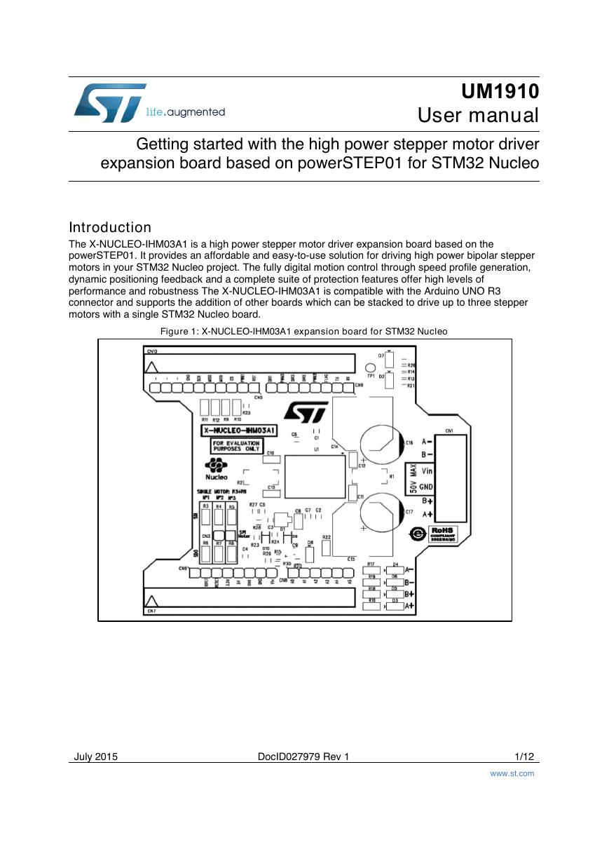
Figure 1: X-NUCLEO-IHM03A1 expansion board for STM32 Nucleo
July 2015
DocID027979 Rev 1
1/12
www.st.com
�
Contents
Contents
UM1910
Getting started ................................................................................ 3
Hardware description and configuration ...................................... 4
2.1
2.2
Selecting the chip select and clock lines of the SPI ......................... 6
Multi-motor configuration .................................................................. 6
Revision history ........................................................................... 11
1
2
3
2/12
DocID027979 Rev 1
�
UM1910
Getting started
1
Getting started
The X-NUCLEO-IHM03A1 expansion board is a high power stepper motor driver covering
a wide range of applications. In particular, the maximum ratings of the board are the
following.
Power stage supply voltage (VS) from 10.5 V to 50 V
Motor phase current up to 10 A r.m.s.
Follow this sequence to start your project with the board:
1. Check the jumper position based on your configuration (see Section 2: "Hardware
description and configuration").
2. Plug the board to the STM32 Nucleo board through Arduino UNO R3 for the X-
NUCLEO-IHM03A1.
3. Supply the board through the input 1 (VS) and 2 (ground) of the connector CN1. The
power OK (green) and fault (red) LEDs will turn on.
4. Develop your application using the examples provided with the firmware library, X-
CUBE-SPN3, high power stepper motor driver software expansion for STM32Cube.
Further support material is available on the powerSTEP01 (www.st.com/powerstep)
and STM32 Nucleo web pages (www.st.com/stm32nucleo).
Up to three expansion boards can be stacked on the same STM32 Nucleo board
as described in Section 2.2: "Multi-motor configuration".
DocID027979 Rev 1
3/12
�
Hardware description and configuration
2
Hardware description and configuration
UM1910
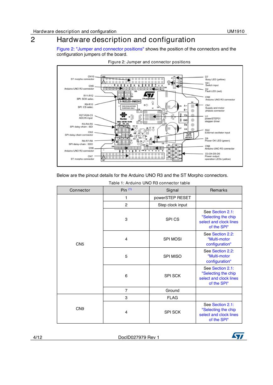
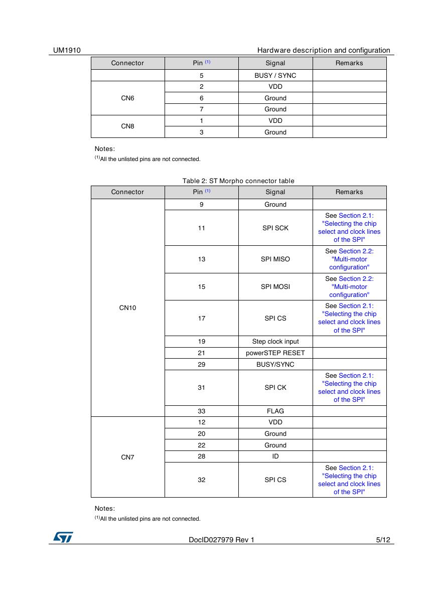
Figure 2: "Jumper and connector positions" shows the position of the connectors and the
configuration jumpers of the board.
Figure 2: Jumper and connector positions
Below are the pinout details for the Arduino UNO R3 and the ST Morpho connectors.
Table 1: Arduino UNO R3 connector table
Connector
Pin (1)
Signal
Remarks
1
2
3
4
5
6
7
3
4
powerSTEP RESET
Step clock input
SPI CS
SPI MOSI
SPI MISO
SPI SCK
Ground
FLAG
SPI SCK
See Section 2.1:
"Selecting the chip
select and clock lines
of the SPI"
See Section 2.2:
"Multi-motor
configuration"
See Section 2.2:
"Multi-motor
configuration"
See Section 2.1:
"Selecting the chip
select and clock lines
of the SPI"
See Section 2.1:
"Selecting the chip
select and clock lines
of the SPI"
CN5
CN9
4/12
DocID027979 Rev 1
�
UM1910
Hardware description and configuration
Connector
Pin (1)
Signal
Remarks
CN6
CN8
5
2
6
7
1
3
BUSY / SYNC
VDD
Ground
Ground
VDD
Ground
Notes:
(1)All the unlisted pins are not connected.
Table 2: ST Morpho connector table
Connector
Pin (1)
9
11
13
15
17
19
21
29
31
33
12
20
22
28
32
CN10
CN7
Signal
Ground
SPI SCK
SPI MISO
SPI MOSI
SPI CS
Remarks
See Section 2.1:
"Selecting the chip
select and clock lines
of the SPI"
See Section 2.2:
"Multi-motor
configuration"
See Section 2.2:
"Multi-motor
configuration"
See Section 2.1:
"Selecting the chip
select and clock lines
of the SPI"
Step clock input
powerSTEP RESET
BUSY/SYNC
SPI CK
FLAG
VDD
Ground
Ground
ID
SPI CS
See Section 2.1:
"Selecting the chip
select and clock lines
of the SPI"
See Section 2.1:
"Selecting the chip
select and clock lines
of the SPI"
Notes:
(1)All the unlisted pins are not connected.
DocID027979 Rev 1
5/12
�
Hardware description and configuration
UM1910
2.1
Selecting the chip select and clock lines of the SPI
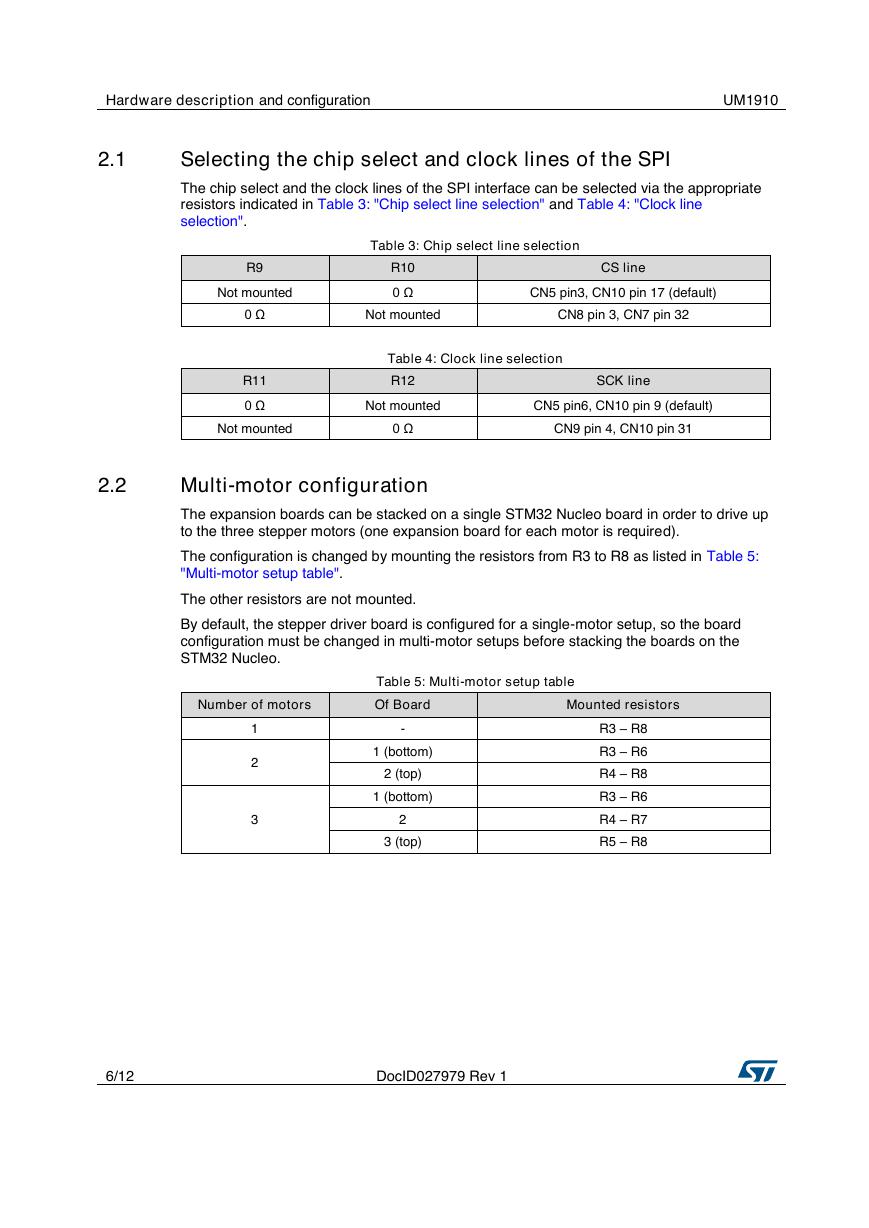
The chip select and the clock lines of the SPI interface can be selected via the appropriate
resistors indicated in Table 3: "Chip select line selection" and Table 4: "Clock line
selection".
Table 3: Chip select line selection
R9
Not mounted
R10
0 Ω
CS line
CN5 pin3, CN10 pin 17 (default)
0 Ω
Not mounted
CN8 pin 3, CN7 pin 32
R11
0 Ω
Table 4: Clock line selection
R12
SCK line
Not mounted
CN5 pin6, CN10 pin 9 (default)
Not mounted
0 Ω
CN9 pin 4, CN10 pin 31
2.2
Multi-motor configuration
The expansion boards can be stacked on a single STM32 Nucleo board in order to drive up
to the three stepper motors (one expansion board for each motor is required).
The configuration is changed by mounting the resistors from R3 to R8 as listed in Table 5:
"Multi-motor setup table".
The other resistors are not mounted.
By default, the stepper driver board is configured for a single-motor setup, so the board
configuration must be changed in multi-motor setups before stacking the boards on the
STM32 Nucleo.
Number of motors
Of Board
Mounted resistors
Table 5: Multi-motor setup table
1
2
3
-
1 (bottom)
2 (top)
1 (bottom)
2
3 (top)
R3 – R8
R3 – R6
R4 – R8
R3 – R6
R4 – R7
R5 – R8
6/12
DocID027979 Rev 1
�
UM1910
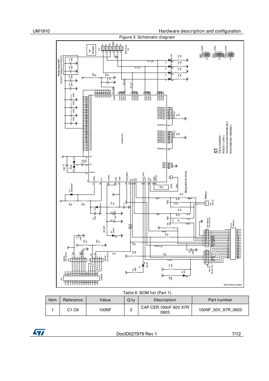
Figure 3: Schematic diagram
Hardware description and configuration
Table 6: BOM list (Part 1)
Item Reference
Value
Q.ty
Description
Part number
1
C1 C6
100NF
2
CAP CER 100nF 50V X7R
0603
100NF_50V_X7R_0603
DocID027979 Rev 1
7/12
�
Hardware description and configuration
UM1910
Item Reference
Value
Q.ty
Description
Part number
2
3
4
5
6
7
8
9
C2
220NF
C3 C7
470NF
C4
C5
C8
C9
3.3NF
NP
47NF
22UF
C10-C13
220NF
C14 C15
68UF
10
C16 C17
NP
11
CN1
MKDS1/6-3.81
12
CN3
CON-1x2
13
CN5
CON-1x10
14
CN6 CN9
CON-1x8
15
CN7 CN10
CON-2x19
16
CN8
CON-1x6
17
18
D1
D2
BAR43
RED
19
D3-D7
YELLOW
20
D8
GREEN
21
D9 D10
BAT46ZFILM
22
MIRE1-
MIRE3
OPTICAL_TARG
ET
1
2
1
1
1
1
4
2
2
1
1
1
2
2
1
1
1
5
1
2
3
CAP CER 220nF 35V X7R
0603
CAP CER 470nF 25V X7R
0603
CAP CER 3.3nF 50V X7R
0603
220NF_35V_X7R_0603
470NF_25V_X7R_0603
3.3NF_50V_X7R_0603
CAP NP 0603
C_NP_0603
CAP CER 47nF 100V
X7R/X7S 0805
CAP TANT 22uF 6V3 10%
PACK-A
CAP CER 220nF 100V
X7R 0805
CAP ALU 68uF 100V SMD
17x17
CAP ALU 68uF 100V
Radial 10x6-P5
Screw connector 6 poles
MKDS 1/6-3.81
THOUGH-HOLE-1x2-Pin
height 14.8 - Body 8.5mn -
pitch 2.54
THOUGH-HOLE-1x10-Pin
height 14.8 - Body 8.5mn -
pitch 2.54
THOUGH-HOLE-1x8-Pin
height 14.8 - Body 8.5mn -
pitch 2.54
THOUGH-HOLE-2x19-Pin
height 14.8 - Body 8.5mn -
pitch 2.54
THOUGH-HOLE-1x6-Pin
height 14.8 - Body 8.5mn -
pitch 2.54
Double Diode High Speed
Switching Diode
LED RED - 0805 -2mcd -
621nm
LED YELLOW - 0805 -
6mcd - 588nm
LED GREEN - 0805 -6mcd
- 569nm
DIODE SCHOTTKY
150MA
47NF_100V_X7R/X7S_0805
22UF_6V3_TANT_PACK-A
220NF_100V_X7R_0805
EEV-FK2A680Q
UHE2A680MPD
MKDS1/6-3.81
SSQ-102-04-F-S
SSQ-110-04-F-S
SSQ-108-04-F-S
SSQ-119-04-L-D
SSQ-106-04-F-S
BAR43
LED _RED
LED_YELLOW
LED_GREEN
BAT46
OPTICAL_TARGET
OPTICAL_TARGET
8/12
DocID027979 Rev 1
�


 V2版本原理图(Capacitive-Fingerprint-Reader-Schematic_V2).pdf
 摄像头工作原理.doc
 VL53L0X简要说明(En.FLVL53L00216).pdf
 原理图(DVK720-Schematic).pdf
 原理图(Pico-Clock-Green-Schdoc).pdf
 原理图(RS485-CAN-HAT-B-schematic).pdf
 File:SIM7500_SIM7600_SIM7800 Series_SSL_Application Note_V2.00.pdf
 ADS1263(Ads1262).pdf
 原理图(Open429Z-D-Schematic).pdf
 用户手册(Capacitive_Fingerprint_Reader_User_Manual_CN).pdf
 CY7C68013A(英文版)(CY7C68013A).pdf
 TechnicalReference_Dem.pdf