(Preliminary)
Product Specification
Part Name: OEL Display Module
Part ID: UG-2828GDEDF11
Doc No.: SAS1-D038-A
Customer:
Approved by
From: Topwin Technology Inc.
Approved by
�
RReevviisseedd HHiissttoorryy
Part Number
Revision
Revision Content
UG-2828GDEDF11
A
New
Revised on
October 15, 2008
�
CCoonntteennttss
RReevviissiioonn HHiissttoorryy ................................................................................................... i
NNoottiiccee ................................................................................................................... ii
CCoonntteennttss .............................................................................................................. iii
11.. BBaassiicc SSppeecciiffiiccaattiioonnss .................................................................................. 1~6
1.1 Display Specifications .................................................................................................1
1.2 Mechanical Specifications ...........................................................................................1
1.3 Active Area & Pixel Construction ...............................................................................1
1.4 Mechanical Drawing....................................................................................................2
1.5 Pin Definition...............................................................................................................3
1.6 Block Diagram.............................................................................................................6
22.. AAbbssoolluuttee MMaaxxiimmuumm RRaattiinnggss .......................................................................... 7
33.. OOppttiiccss && EElleeccttrriiccaall CChhaarraacctteerriissttiiccss......................................................... 8~12
3.1 Optics Characteristics ..................................................................................................8
3.2 DC Characteristics .......................................................................................................8
3.3 AC Characteristics .......................................................................................................9
3.3.1 68XX-Series MPU Parallel Interface Timing Characteristics...........................9
3.3.2 80XX-Series MPU Parallel Interface Timing Characteristics.........................10
3.3.3 Serial Interface Timing Characteristics (4-wire SPI).......................................11
3.3.4 Serial Interface Timing Characteristics (3-wire SPI).......................................12
44.. FFuunnccttiioonnaall SSppeecciiffiiccaattiioonn ....................................................................... 13~14
4.1 Commands .................................................................................................................13
4.2 Power down and Power up Sequence ........................................................................13
4.2.1 Power up Sequence..........................................................................................13
4.2.2 Power down Sequence .....................................................................................13
4.3 Reset Circuit...............................................................................................................13
4.4 Actual Application Example......................................................................................14
55.. RReelliiaabbiilliittyy...................................................................................................... 15
5.1 Contents of Reliability Tests......................................................................................15
5.2 Lifetime......................................................................................................................15
5.3 Failure Check Standard..............................................................................................15
66.. OOuuttggooiinngg QQuuaalliittyy CCoonnttrrooll SSppeecciiffiiccaattiioonnss.............................................. 16~20
6.1 Environment Required...............................................................................................16
6.2 Sampling Plan ............................................................................................................16
6.3 Criteria & Acceptable Quality Level .........................................................................16
6.3.1 Cosmetic Check (Display Off) in Non-Active Area........................................16
6.3.2 Cosmetic Check (Display Off) in Active Area.................................................19
6.3.3 Pattern Check (Display On) in Active Area.....................................................20
77.. PPaacckkaaggee SSppeecciiffiiccaattiioonnss ................................................................................ 21
�
88.. PPrreeccaauuttiioonnss WWhheenn UUssiinngg TThheessee OOEELL DDiissppllaayy MMoodduulleess....................... 22~24
8.1 Handling Precautions.................................................................................................22
8.2 Storage Precautions....................................................................................................23
8.3 Designing Precautions ...............................................................................................23
8.4 Precautions when disposing of the OEL display modules.........................................24
8.5 Other Precautions.......................................................................................................24
�
11.. BBaassiicc SSppeecciiffiiccaattiioonnss
1.1 Display Specifications
1) Display Mode:
2) Display Color:
3) Drive Duty:
Passive Matrix
262,144 Colors (Maximum)
1/128 Duty
1.2 Mechanical Specifications
1) Outline Drawing: According to the annexed outline drawing
2) Number of Pixels: 128 (RGB) × 128
3) Panel Size:
4) Active Area:
5) Pixel Pitch:
6) Pixel Size:
7) Weight:
33.80 × 34.00 × 1.60 (mm)
26.855 × 26.864 (mm)
0.07 × 0.21 (mm)
0.045 × 0.194 (mm)
3.75 (g)
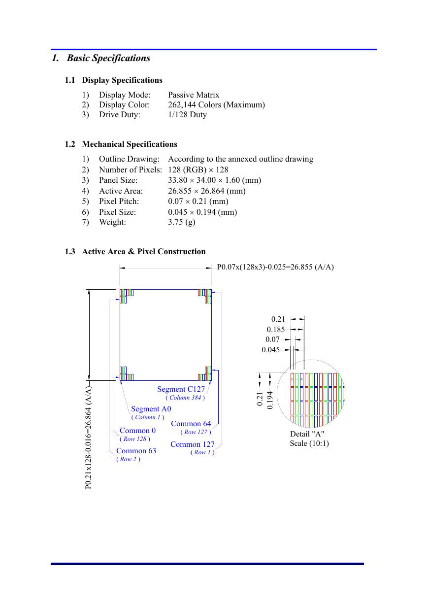
1.3 Active Area & Pixel Construction
P0.07x(128x3)-0.025=26.855 (A/A)
0.21
0.185
0.07
0.045
R G B
Segment C127
( Column 384 )
Segment A0
( Column 1 )
Common 0
( Row 128 )
Common 63
( Row 2 )
Common 64
( Row 127 )
Common 127
( Row 1 )
)
A
A
/
(
.
4
6
8
6
2
=
6
1
0
.
0
-
8
2
1
x
1
2
.
0
P
1
2
.
0
4
9
1
0
.
Detail "A"
Scale (10:1)
�
0.65±0.5
(2.472)
(3.472)
(
1
1
)
.
(
2
1
)
.
0
.
5
±
0
5
.
.
P
0
2
1
x
1
2
8
-
0
.
0
1
6
=
2
6
8
6
4
(
.
A
A
/
)
3
0
5
.
(
P
o
l
a
r
i
z
e
r
)
.
2
8
8
6
4
(
V
A
/
)
3
2
±
0
.
2
(
C
a
p
S
i
z
e
)
3
4
±
0
.
2
(
P
a
n
e
l
S
i
z
e
)
.
(
4
8
3
5
)
1
4
.
3
5
±
0
.
2
7
.
7
1
5
.
3
5
±
0
.
1
4
.
3
6
5
3
.
1
3
9
3
33.8±0.2 (Panel Size)
33.8±0.2 (Cap Size)
32.5 (Polarizer)
28.855 (V/A)
P0.07x(128x3)-0.025=26.855 (A/A)
10
5
1.6±0.1
t
"A"
8
Active Area 1.50"
128(RGB) x 128 Pixels
=
0
R
e
m
o
v
e
T
a
p
e
.
1
5
m
m
M
a
x
t
.
=
0
2
m
m
P
o
l
a
r
i
z
e
r
2
5
x
6
7
x
0
.
.
1
m
m
P
r
o
t
e
c
t
i
v
e
F
i
l
m
1
30
2-R0.5±0.05
)
)
C
o
n
t
a
c
t
S
i
d
e
D
N
G
(
.
.
C
N
H
M
O
C
V
C
C
V
I
O
D
D
V
L
S
V
.
.
C
N
7
D
6
D
5
D
4
D
3
D
2
D
1
D
0
D
#
D
R
E
/
#
W
R
/
0
S
B
1
S
B
#
S
C
#
C
D
/
#
S
E
R
F
E
R
I
1
O
I
P
G
0
O
I
P
G
.
.
C
N
D
D
V
I
C
V
S
S
V
.
.
C
N
D
N
G
(
.
.
C
N
(
2
3
.
4
)
.
(
3
1
1
1
)
(
3
5
6
)
.
(
1
6
)
.
(2.3)
(
4
2
.
7
)
(
8
.
7
)
(
5
.
4
)
(1.6)
G
l
u
e
4
±
0
.
5
(
S
t
i
f
f
e
n
e
r
)
Notes:
(2.985)
P0.50x(30-1)=14.5±0.05 (W0.30±0.03)
15.5±0.2
24±0.1
27.83±0.2
1. Driver IC: SSD1351
2. Die Size: 10700um x 1500um
3. COF Number: SSD1351U3
4. Interface:
8-bits 68XX/80XX Parallel, 3-/4-wire SPI
5. General Tolerance: ±0.30
6. The total thickness (1.70 Max) is without polarizer protective film & remove tape.
The actual assembled total thickness with above materials should be 1.95 Max.
0.3±0.03
0.80 Max
(Reference Mechnical Design)
Detail "A"
Scale (10:1)
Customer Approval
Signature
Topwin Technology Inc.
Unless Otherwise Specified
mm
Unit
General Roughness
Tolerance
Dimension
Angle
±0.3
±1
Title
By
Date
UG-2828GDEDF11 Folding Type OEL Display Module
Pixel Number: 128(RGB) x 128, 262144 Colors, COF Package
Drawn
Humphrey Lin
20080815
E.E.
Sean Lai
20080815
Panel / E.
Ivy Lo
20080815
P.M.
Cherry Lin
20080815
Item
A
Date
20080815
Remark
Original Drawing
Segment C127
( Column 384 )
Common 64
( Row 127 )
Common 127
( Row 1 )
Segment A0
( Column 1 )
Common 0
( Row 128 )
Common 63
( Row 2 )
0.21
0.185
0.07
0.045
R G B
0
.
2
1
0
.
1
9
4
Pin
1
2
3
4
5
6
7
8
9
10
11
12
13
14
15
16
17
18
19
20
21
22
23
24
25
26
27
28
29
30
Symbol
N.C. (GND)
VCC
VCOMH
VDDIO
VSL
N.C.
D7
D6
D5
D4
D3
D2
D1
D0
E/RD#
R/W#
BS0
BS1
CS#
D/C#
RES#
IREF
GPIO1
GPIO0
N.C.
VDD
VCI
VSS
N.C.
N.C. (GND)
Drawing Number
DFE2828CNCF38
Material
Rev.
A
Soda Lime / Polyimide
Scale
1:1
Sheet
1 of 1
Size
A3
�
1.5 Pin Definition
Pin Number
PPoowweerr SSuuppppllyy
Symbol Type
Function
27
26
VCI
VDD
P
P
4
VDDIO
P
VSS
VCC
28
2
DDrriivveerr
22
IREF
P
P
I
3
5
VCOMH
P
VSL
P
EExxtteerrnnaall IICC CCoonnttrrooll
24
23
GPIO0
GPIO1
I/O
PPoowweerr SSuuppppllyy ffoorr OOppeerraattiioonn
This is a voltage supply pin. It must be connected to
external source & always be equal to or higher than VDD
& VDDIO.
PPoowweerr SSuuppppllyy ffoorr CCoorree LLooggiicc CCiirrccuuiitt
This is a voltage supply pin which is regulated internally
from VCI. A capacitor should be connected between
this pin & VSS under all circumstances.
PPoowweerr SSuuppppllyy ffoorr II//OO PPiinn
This pin is a power supply pin of I/O buffer. It should
be connected to VCI or external source. All I/O signal
should have VIH reference to VDDIO. When I/O signal
pins (BS0~BS1, D0~D7, control signals…) pull high,
they should be connected to VDDIO.
GGrroouunndd ooff OOEELL SSyysstteemm
This is a ground pin. It also acts as a reference for the
logic pins, the OEL driving voltages, and the analog
circuits. It must be connected to external ground.
PPoowweerr SSuuppppllyy ffoorr OOEELL PPaanneell
This is the most positive voltage supply pin of the chip.
It must be connected to external source.
CCuurrrreenntt RReeffeerreennccee ffoorr BBrriigghhttnneessss AAddjjuussttmmeenntt
This pin is segment current reference pin. A resistor
should be connected between this pin and VSS. Set the
current lower than 12.5uA.
VVoollttaaggee OOuuttppuutt HHiigghh LLeevveell ffoorr CCOOMM SSiiggnnaall
This pin is the input pin for the voltage output high level
for COM signals. A tantalum capacitor should be
connected between this pin and VSS.
VVoollttaaggee OOuuttppuutt LLooww LLeevveell ffoorr SSEEGG SSiiggnnaall
This is segment voltage reference pin.
When external VSL is not used, this pin should be left
open.
When external VSL is used, this pin should connect with
resistor and diode to ground.
GGeenneerraall PPuurrppoossee IInnppuutt//OOuuttppuutt
These pins could be left open individually or have signal
inputted/outputted. They are able to use as the external
DC/DC converter circuit enabled/disabled control or other
applications.
�
1.5 Pin Definition (Continued)
Pin Number
IInntteerrffaaccee
Symbol
I/O
Function
17
18
21
19
BS0
BS1
RES#
CS#
20
D/C#
I
I
I
I
15
E/RD#
I
16
R/W#
I
7~14
D7~D0
I/O
CCoommmmuunniiccaattiinngg PPrroottooccooll SSeelleecctt
These pins are MCU interface selection input. See the
following table:
BS0
1
0
1
0
BS1
0
0
1
1
3-wire SPI
4-wire SPI
68XX-parallel (8-bit)
80XX-parallel (8-bit)
to
the command register.
PPoowweerr RReesseett ffoorr CCoonnttrroolllleerr aanndd DDrriivveerr
This pin is reset signal input. When the pin is low,
initialization of the chip is executed.
CChhiipp SSeelleecctt
This pin is the chip select input. The chip is enabled for
MCU communication only when CS# is pulled low.
DDaattaa//CCoommmmaanndd CCoonnttrrooll
This pin is Data/Command control pin. When the pin is
pulled high, the input at D7~D0 is treated as display data.
When the pin is pulled low, the input at D7~D0 will be
transferred
For detail
relationship to MCU interface signals, please refer to the
Timing Characteristics Diagrams.
When 3-wire serial mode is selected, this pin must be
connected to VSS.
RReeaadd//WWrriittee EEnnaabbllee oorr RReeaadd
This pin is MCU interface input. When interfacing to a
68XX-series microprocessor, this pin will be used as the
Enable (E) signal. Read/write operation is initiated when
this pin is pulled high and the CS# is pulled low.
When connecting to an 80XX-microprocessor, this pin
receives the Read (RD#) signal. Data read operation is
initiated when this pin is pulled low and CS# is pulled
low.
When serial mode is selected, this pin must be connected
to VSS.
RReeaadd//WWrriittee SSeelleecctt oorr WWrriittee
This pin is MCU interface input. When interfacing to a
68XX-series microprocessor, this pin will be used as
Read/Write (R/W#) selection input. Pull this pin to
“High” for read mode and pull it to “Low” for write
mode.
When 80XX interface mode is selected, this pin will be
the Write (WR#) input. Data write operation is initiated
when this pin is pulled low and the CS# is pulled low.
When serial mode is selected, this pin must be connected
to VSS.
HHoosstt DDaattaa IInnppuutt//OOuuttppuutt BBuuss
These pins are 8-bit bi-directional data bus to be
connected to the microprocessor’s data bus. When serial
mode is selected, D1 will be the serial data input SDIN
and D0 will be the serial clock input SCLK.
Unused pins must be connected to VSS except for D2.
4
�


 V2版本原理图(Capacitive-Fingerprint-Reader-Schematic_V2).pdf
 摄像头工作原理.doc
 VL53L0X简要说明(En.FLVL53L00216).pdf
 原理图(DVK720-Schematic).pdf
 原理图(Pico-Clock-Green-Schdoc).pdf
 原理图(RS485-CAN-HAT-B-schematic).pdf
 File:SIM7500_SIM7600_SIM7800 Series_SSL_Application Note_V2.00.pdf
 ADS1263(Ads1262).pdf
 原理图(Open429Z-D-Schematic).pdf
 用户手册(Capacitive_Fingerprint_Reader_User_Manual_CN).pdf
 CY7C68013A(英文版)(CY7C68013A).pdf
 TechnicalReference_Dem.pdf