Front Cover
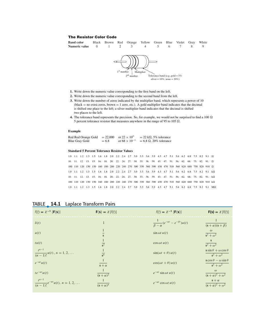
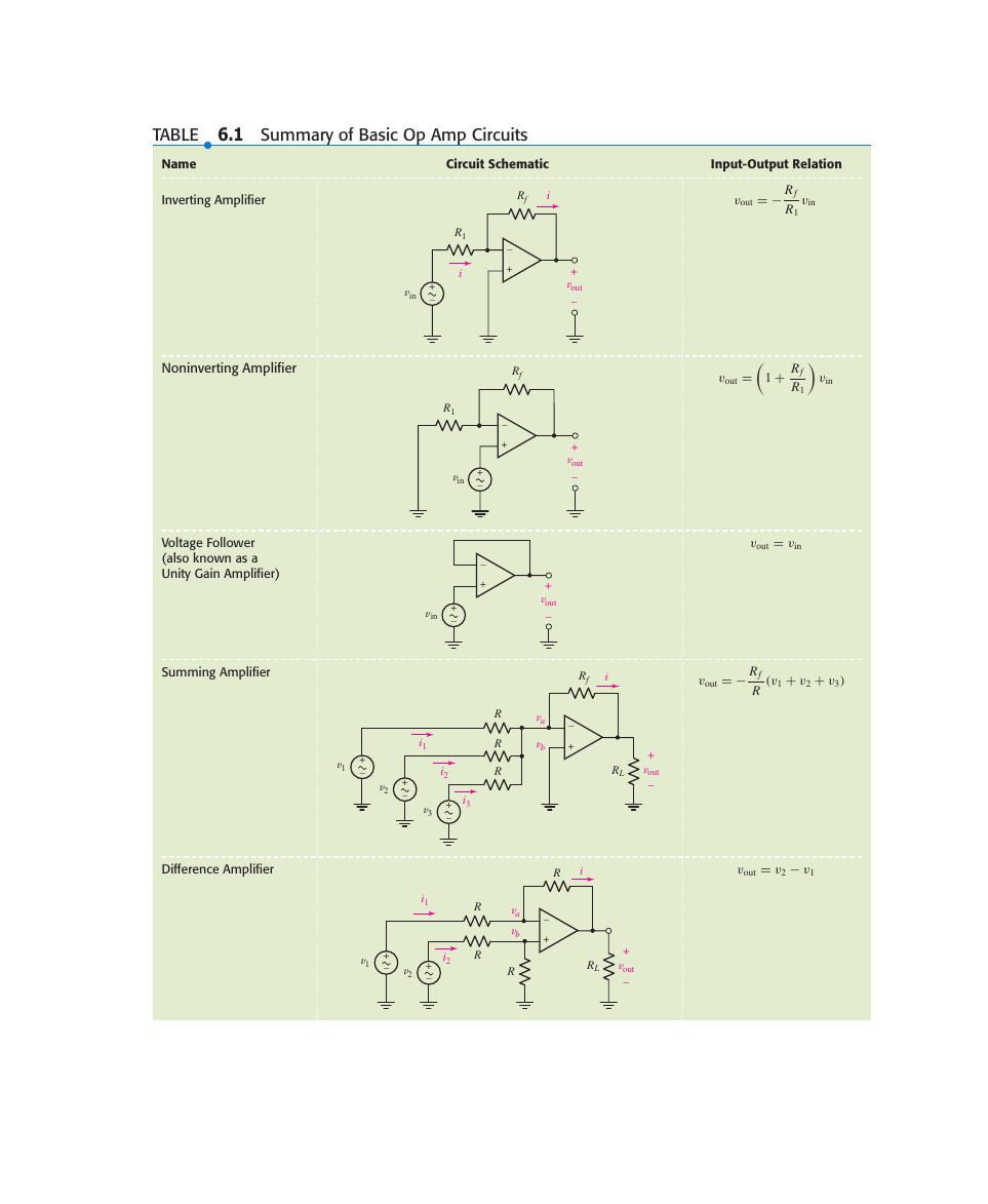
Inside Front Cover (Reference Pages)
Title Page
Copyright Page
Dedication Page
About the Authors
Brief Contents
CONTENTS
Preface
1 INTRODUCTION
1.1 Overview of Text
1.2 Relationship of Circuit Analysis to Engineering
1.3 Analysis and Design
1.4 Computer-Aided Analysis
1.5 Successful Problem-Solving Strategies
READING FURTHER
2 BASIC COMPONENTS AND ELECTRIC CIRCUITS
2.1 Units and Scales
2.2 Charge, Current, Voltage, and Power
Current
Voltage
Power
2.3 Voltage and Current Sources
Independent Voltage Sources
Independent Current Sources
Dependent Sources
Networks and Circuits
2.4 Ohm’s Law
Power Absorption
Conductance
SUMMARY AND REVIEW
READING FURTHER
EXERCISES
3 VOLTAGE AND CURRENT LAWS
3.1 Nodes, Paths, Loops, and Branches
3.2 Kirchhoff’s Current Law
3.3 Kirchhoff’s Voltage Law
3.4 The Single-Loop Circuit
3.5 The Single-Node-Pair Circuit
3.6 Series and Parallel Connected Sources
3.7 Resistors in Series and Parallel
3.8 Voltage and Current Division
SUMMARY AND REVIEW
READING FURTHER
EXERCISES
4 BASIC NODAL AND MESH ANALYSIS
4.1 Nodal Analysis
4.2 The Supernode
4.3 Mesh Analysis
4.4 The Supermesh
4.5 Nodal vs. Mesh Analysis: A Comparison
4.6 Computer-Aided Circuit Analysis
SUMMARY AND REVIEW
READING FURTHER
EXERCISES
5 HANDY CIRCUIT ANALYSIS TECHNIQUES
5.1 Linearity and Superposition
Linear Elements and Linear Circuits
The Superposition Principle
5.2 Source Transformations
Practical Voltage Sources
Practical Current Sources
Equivalent Practical Sources
Several Key Points
5.3 Thévenin and Norton Equivalent Circuits
Thévenin’s Theorem
A Few Key Points
Norton’s Theorem
When Dependent Sources Are Present
A Quick Recap of Procedures
5.4 Maximum Power Transfer
5.5 Delta-Wye Conversion
5.6 Selecting an Approach: A Summary of Various Techniques
SUMMARY AND REVIEW
READING FURTHER
EXERCISES
6 THE OPERATIONAL AMPLIFIER
6.1 Background
6.2 The Ideal Op Amp: A Cordial Introduction
6.3 Cascaded Stages
6.4 Circuits for Voltage and Current Sources
A Reliable Voltage Source
A Reliable Current Source
6.5 Practical Considerations
A More Detailed Op Amp Model
Derivation of the Ideal Op Amp Rules
Common-Mode Rejection
Negative Feedback
Saturation
Input Offset Voltage
Slew Rate
Packaging
6.6 Comparators and the Instrumentation Amplifier
The Comparator
The Instrumentation Amplifier
SUMMARY AND REVIEW
READING FURTHER
EXERCISES
7 CAPACITORS AND INDUCTORS
7.1 The Capacitor
Ideal Capacitor Model
Integral Voltage-Current Relationships
Energy Storage
7.2 The Inductor
Ideal Inductor Model
Integral Voltage-Current Relationships
Energy Storage
7.3 Inductance and Capacitance Combinations
Inductors in Series
Inductors in Parallel
Capacitors in Series
Capacitors in Parallel
7.4 Consequences of Linearity
7.5 Simple Op Amp Circuits with Capacitors
7.6 Duality
7.7 Modeling Capacitors and Inductors with PSpice
SUMMARY AND REVIEW
READING FURTHER
EXERCISES
8 BASIC RL AND RC CIRCUITS
8.1 The Source-Free RL Circuit
A Direct Approach
An Alternative Approach
A More General Solution Approach
A Direct Route: The Characteristic Equation
Accounting for the Energy
8.2 Properties of the Exponential Response
8.3 The Source-Free RC Circuit
8.4 A More General Perspective
General RL Circuits
Slicing Thinly: The Distinction Between 0[Sup(+)] and 0[Sup(-)]
General RC Circuits
8.5 The Unit-Step Function
Physical Sources and the Unit-Step Function
The Rectangular Pulse Function
8.6 Driven RL Circuits
A More Direct Procedure
Developing an Intuitive Understanding
8.7 Natural and Forced Response
The Natural Response
The Forced Response
Determination of the Complete Response
8.8 Driven RC Circuits
8.9 Predicting the Response of Sequentially Switched Circuits
Case I: Time Enough to Fully Charge and Fully Discharge
Case II: Time Enough to Fully Charge But Not Fully Discharge
Case III: No Time to Fully Charge But Time to Fully Discharge
Case IV: No Time to Fully Charge or Even Fully Discharge
SUMMARY AND REVIEW
READING FURTHER
EXERCISES
9 THE RLC CIRCUIT
9.1 The Source-Free Parallel Circuit
Obtaining the Differential Equation for a Parallel RLC Circuit
Solution of the Differential Equation
Definition of Frequency Terms
9.2 The Overdamped Parallel RLC Circuit
Finding Values for A[Sub(1)] and A[Sub(2)]
Graphical Representation of the Overdamped Response
9.3 Critical Damping
Form of a Critically Damped Response
Finding Values for A[Sub(1)] and A[Sub(2)]
Graphical Representation of the Critically Damped Response
9.4 The Underdamped Parallel RLC Circuit
The Form of the Underdamped Response
Finding Values for BB[Sub(1)] and B[Sub(2)]
Graphical Representation of the Underdamped Response
The Role of Finite Resistance
9.5 The Source-Free Series RLC Circuit
A Brief Résumé of the Series Circuit Response
9.6 The Complete Response of the RLC Circuit
The Easy Part
The Other Part
A Quick Summary of the Solution Process
9.7 The Lossless LC Circuit
SUMMARY AND REVIEW
READING FURTHER
EXERCISES
10 SINUSOIDAL STEADY-STATE ANALYSIS
10.1 Characteristics of Sinusoids
Lagging and Leading
Converting Sines to Cosines
10.2 Forced Response to Sinusoidal Functions
The Steady-State Response
A More Compact and User-Friendly Form
10.3 The Complex Forcing Function
Imaginary Sources Lead to . . . Imaginary Responses
Applying a Complex Forcing Function
An Algebraic Alternative to Differential Equations
10.4 The Phasor
The Resistor
The Inductor
The Capacitor
Kirchhoff’s Laws Using Phasors
10.5 Impedance and Admittance
Series Impedance Combinations
Parallel Impedance Combinations
Reactance
Admittance
10.6 Nodal and Mesh Analysis
10.7 Superposition, Source Transformations and Thévenin’s Theorem
10.8 Phasor Diagrams
SUMMARY AND REVIEW
READING FURTHER
EXERCISES
11 AC CIRCUIT POWER ANALYSIS
11.1 Instantaneous Power
Power Due to Sinusoidal Excitation
11.2 Average Power
Average Power for Periodic Waveforms
Average Power in the Sinusoidal Steady State
Average Power Absorbed by an Ideal Resistor
Average Power Absorbed by Purely Reactive Elements
Maximum Power Transfer
Average Power for Nonperiodic Functions
11.3 Effective Values of Current and Voltage
Effective Value of a Periodic Waveform
Effective (RMS) Value of a Sinusoidal Waveform
Use of RMS Values to Compute Average Power
Effective Value with Multiple-Frequency Circuits
11.4 Apparent Power and Power Factor
11.5 Complex Power
The Power Triangle
Power Measurement
SUMMARY AND REVIEW
READING FURTHER
EXERCISES
12 POLYPHASE CIRCUITS
12.1 Polyphase Systems
Double-Subscript Notation
12.2 Single-Phase Three-Wire Systems
Effect of Finite Wire Impedance
12.3 Three-Phase Y-Y Connection
Line-to-Line Voltages
12.4 The Delta (Δ) Connection
Δ-Connected Sources
12.5 Power Measurement in Three-Phase Systems
Use of the Wattmeter
The Wattmeter in a Three-Phase System
The Two-Wattmeter Method
SUMMARY AND REVIEW
READING FURTHER
EXERCISES
13 MAGNETICALLY COUPLED CIRCUITS
13.1 Mutual Inductance
Coefficient of Mutual Inductance
Dot Convention
Combined Mutual and Self-Induction Voltage
Physical Basis of the Dot Convention
13.2 Energy Considerations
Equality of M[Sub(12)] and M[Sub(21)]
Establishing an Upper Limit for M
The Coupling Coefficient
13.3 The Linear Transformer
Reflected Impedance
T and π Equivalent Networks
13.4 The Ideal Transformer
Turns Ratio of an Ideal Transformer
Use of Transformers for Impedance Matching
Use of Transformers for Current Adjustment
Use of Transformers for Voltage Level Adjustment
Voltage Relationship in the Time Domain
Equivalent Circuits
SUMMARY AND REVIEW
READING FURTHER
EXERCISES
14 COMPLEX FREQUENCY AND THE LAPLACE TRANSFORM
14.1 Complex Frequency
The General Form
The DC Case
The Exponential Case
The Sinusoidal Case
The Exponentially Damped Sinusoidal Case
The Relationship of s to Reality
14.2 The Damped Sinusoidal Forcing Function
14.3 Definition of the Laplace Transform
The Two-Sided Laplace Transform
The Two-Sided Inverse Laplace Transform
The One-Sided Laplace Transform
14.4 Laplace Transforms of Simple Time Functions
The Unit-Step Function u(t)
The Unit-Impulse Function δ(t – t[Sub(0)])
The Exponential Function e[Sup(–αt)]
The Ramp Function tu(t)
14.5 Inverse Transform Techniques
The Linearity Theorem
Inverse Transform Techniques for Rational Functions
Distinct Poles and the Method of Residues
Repeated Poles
14.6 Basic Theorems for the Laplace Transform
Time Differentiation Theorem
Time-Integration Theorem
Laplace Transforms of Sinusoids
The Time-Shift Theorem
14.7 The Initial-Value and Final-Value Theorems
The Initial-Value Theorem
The Final-Value Theorem
SUMMARY AND REVIEW
READING FURTHER
EXERCISES
15 CIRCUIT ANALYSIS IN THE s-DOMAIN
15.1 Z(s) and Y(s)
Resistors in the Frequency Domain
Inductors in the Frequency Domain
Modeling Inductors in the s-Domain
Modeling Capacitors in the s-Domain
15.2 Nodal and Mesh Analysis in the s-Domain
15.3 Additional Circuit Analysis Techniques
15.4 Poles, Zeros, and Transfer Functions
15.5 Convolution
The Impulse Response
The Convolution Integral
Convolution and Realizable Systems
Graphical Method of Convolution
Convolution and the Laplace Transform
Further Comments on Transfer Functions
15.6 The Complex-Frequency Plane
Pole-Zero Constellations
15.7 Natural Response and the s Plane
A More General Perspective
A Special Case
15.8 A Technique for Synthesizing the Voltage Ratio H(s) = V[Sub(out)]/V[Sub(in)]
SUMMARY AND REVIEW
READING FURTHER
EXERCISES
16 FREQUENCY RESPONSE
16.1 Parallel Resonance
Resonance
Resonance and the Voltage Response
Quality Factor
Other Interpretations of Q
Damping Factor
16.2 Bandwidth and High-Q Circuits
Bandwidth
Approximations for High-Q Circuits
16.3 Series Resonance
16.4 Other Resonant Forms
Equivalent Series and Parallel Combinations
16.5 Scaling
16.6 Bode Diagrams
The Decibel (dB) Scale
Determination of Asymptotes
Smoothing Bode Plots
Multiple Terms
Phase Response
Additional Considerations in Creating Bode Plots
Higher-Order Terms
Complex Conjugate Pairs
16.7 Basic Filter Design
Passive Low-Pass and High-Pass Filters
Bandpass Filters
Active Filters
16.8 Advanced Filter Design
The Sallen-Key Amplifier
SUMMARY AND REVIEW
READING FURTHER
EXERCISES
17 TWO-PORT NETWORKS
17.1 One-Port Networks
17.2 Admittance Parameters
17.3 Some Equivalent Networks
17.4 Impedance Parameters
17.5 Hybrid Parameters
17.6 Transmission Parameters
SUMMARY AND REVIEW
READING FURTHER
EXERCISES
18 FOURIER CIRCUIT ANALYSIS
18.1 Trigonometric Form of the Fourier Series
Harmonics
The Fourier Series
Some Useful Trigonometric Integrals
Evaluation of the Fourier Coefficients
Line and Phase Spectra
18.2 The Use of Symmetry
Even and Odd Symmetry
Symmetry and Fourier Series Terms
Half-Wave Symmetry
18.3 Complete Response to Periodic Forcing Functions
18.4 Complex Form of the Fourier Series
The Sampling Function
18.5 Definition of the Fourier Transform
18.6 Some Properties of the Fourier Transform
Physical Significance of the Fourier Transform
18.7 Fourier Transform Pairs for Some Simple Time Functions
The Unit-Impulse Function
The Constant Forcing Function
The Signum Function
The Unit-Step Function
18.8 The Fourier Transform of a General Periodic Time Function
18.9 The System Function and Response in the Frequency Domain
18.10 The Physical Significance of the System Function
Epilogue
SUMMARY AND REVIEW
READING FURTHER
EXERCISES
APPENDICES
1 AN INTRODUCTION TO NETWORK TOPOLOGY
2 SOLUTION OF SIMULTANEOUS EQUATIONS
3 A PROOF OF THÉVENIN’S THEOREM
4 A PSPICE® TUTORIAL
5 COMPLEX NUMBERS
6 A BRIEF MATLAB® TUTORIAL
7 ADDITIONAL LAPLACE TRANSFORM THEOREMS
INDEX
Inside Back Cover (Reference Pages)





 2023年江西萍乡中考道德与法治真题及答案.doc
 2012年重庆南川中考生物真题及答案.doc
 2013年江西师范大学地理学综合及文艺理论基础考研真题.doc
 2020年四川甘孜小升初语文真题及答案I卷.doc
 2020年注册岩土工程师专业基础考试真题及答案.doc
 2023-2024学年福建省厦门市九年级上学期数学月考试题及答案.doc
 2021-2022学年辽宁省沈阳市大东区九年级上学期语文期末试题及答案.doc
 2022-2023学年北京东城区初三第一学期物理期末试卷及答案.doc
 2018上半年江西教师资格初中地理学科知识与教学能力真题及答案.doc
 2012年河北国家公务员申论考试真题及答案-省级.doc
 2020-2021学年江苏省扬州市江都区邵樊片九年级上学期数学第一次质量检测试题及答案.doc
 2022下半年黑龙江教师资格证中学综合素质真题及答案.doc