A global approach to functional safety
Dr.-Ing. M. Leibbrandt, Getrag Ford Transmissions GmbH
�
Agenda
1. Finding all hazards
2. Determination of safety goals
3. Definition of safety functions
Local safety architecture
Global safety architecture
4. Hardware architectural metrics
5. Bus communication
2
© GETRAG, 14th International VDI Congress, Drivetrain for Vehicles, Friedrichshafen June 2014, Dr. Martin Leibbrandt
June 24, 2014
�
Finding all hazards
�
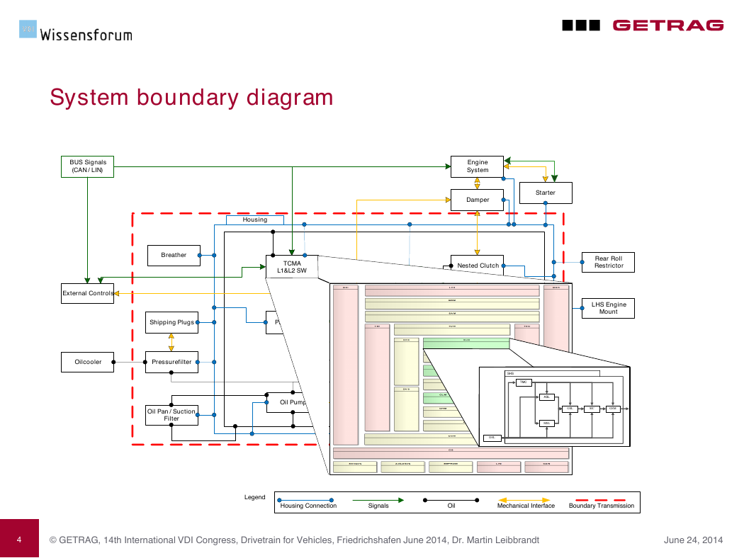
System boundary diagram
BUS Signals
( CAN / LIN )
External Controls
Engine
System
Damper
Starter
Housing
Breather
TCMA
L 1 & L 2 SW
Nested Clutch
Rear Roll
Restrictor
Hydraulic
Controls
Gears / Shafts /
Bearings
LHS Engine
Mount
Shipping Plugs
Parksystem
Oilcooler
Pressurefilter
Internal Controls
Synchronizer
Oil Pan / Suction
Filter
Oil Pump
Oil Flow
Differential
Shaft Drives
Legend :
Housing Connection
Signals
Oil
Mechanical Interface
Boundary Transmission
4
© GETRAG, 14th International VDI Congress, Drivetrain for Vehicles, Friedrichshafen June 2014, Dr. Martin Leibbrandt
June 24, 2014
SHS TMC DSL ASL MSL GSL SIC GSM �
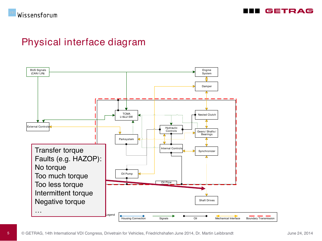
Physical interface diagram
BUS Signals
( CAN / LIN )
External Controls
Transfer torque
Faults (e.g. HAZOP):
No torque
Too much torque
Too less torque
Intermittent torque
Negative torque
…
Engine
System
Damper
Nested Clutch
Hydraulic
Controls
Gears / Shafts /
Bearings
Internal Controls
Synchronizer
TCMA
L 1 & L 2 SW
Parksystem
Oil Pump
Oil Flow
Shaft Drives
Legend :
Housing Connection
Signals
Oil
Mechanical Interface
Boundary Transmission
5
© GETRAG, 14th International VDI Congress, Drivetrain for Vehicles, Friedrichshafen June 2014, Dr. Martin Leibbrandt
June 24, 2014
�
Safety Goals
�
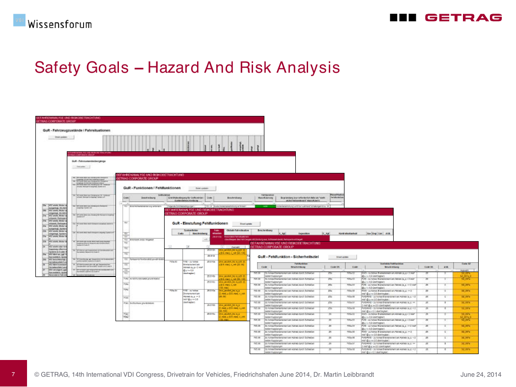
Safety Goals – Hazard And Risk Analysis
7
© GETRAG, 14th International VDI Congress, Drivetrain for Vehicles, Friedrichshafen June 2014, Dr. Martin Leibbrandt
June 24, 2014
�
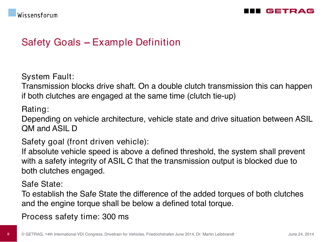
Safety Goals – Example Definition
System Fault:
Transmission blocks drive shaft. On a double clutch transmission this can happen
if both clutches are engaged at the same time (clutch tie-up)
Rating:
Depending on vehicle architecture, vehicle state and drive situation between ASIL
QM and ASIL D
Safety goal (front driven vehicle):
If absolute vehicle speed is above a defined threshold, the system shall prevent
with a safety integrity of ASIL C that the transmission output is blocked due to
both clutches engaged.
Safe State:
To establish the Safe State the difference of the added torques of both clutches
and the engine torque shall be below a defined total torque.
Process safety time: 300 ms
© GETRAG, 14th International VDI Congress, Drivetrain for Vehicles, Friedrichshafen June 2014, Dr. Martin Leibbrandt
8
June 24, 2014
�


 2023年江西萍乡中考道德与法治真题及答案.doc
 2012年重庆南川中考生物真题及答案.doc
 2013年江西师范大学地理学综合及文艺理论基础考研真题.doc
 2020年四川甘孜小升初语文真题及答案I卷.doc
 2020年注册岩土工程师专业基础考试真题及答案.doc
 2023-2024学年福建省厦门市九年级上学期数学月考试题及答案.doc
 2021-2022学年辽宁省沈阳市大东区九年级上学期语文期末试题及答案.doc
 2022-2023学年北京东城区初三第一学期物理期末试卷及答案.doc
 2018上半年江西教师资格初中地理学科知识与教学能力真题及答案.doc
 2012年河北国家公务员申论考试真题及答案-省级.doc
 2020-2021学年江苏省扬州市江都区邵樊片九年级上学期数学第一次质量检测试题及答案.doc
 2022下半年黑龙江教师资格证中学综合素质真题及答案.doc