Operating Instructions
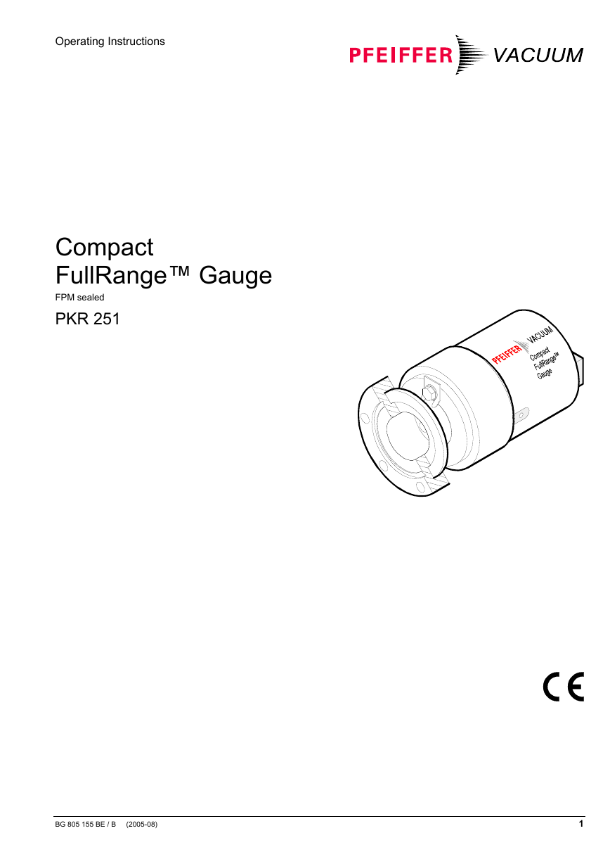
Compact
FullRange™ Gauge
FPM sealed
PKR 251
BG 805 155 BE / B (2005-08)
1
�
Table of Contents
Product Identification
Validity
Intended Use
Functional Principle
1 Safety
1.1 Symbols Used
1.2 Personnel Qualifications
1.3 Safety Information
1.4 Liability and Warranty
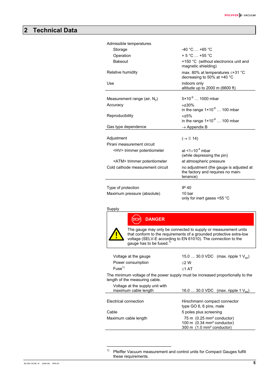
2 Technical Data
3 Installation
3.1 Installation
3.1.1 Removing the Magnet Unit (Only for Gauges With CF Flanges)
3.2 Electrical Connection
3.2.1 Use With a Pfeiffer Vacuum Measurement Unit
3.2.2 Use With Another Evaluation Unit
4 Operation
4.1 Measurement Principle, Measuring Behavior
5 Maintenance
5.1 Adjusting the Gauge
5.2 Cleaning the Gauge / Replacing Parts
5.2.1 Disassembling the Gauge
5.2.2 Cleaning the Gauge
5.2.3 Reassembling the Gauge
5.3 What to Do in Case of Problems
6 Removing the Gauge From the Vacuum System
7 Returning the Product
8 Accessories
9 Spare Parts
10 Disposal
Appendix
A: Measuring Signal vs. Pressure
B: Gas Type Dependence
Declaration of Contamination
For cross references within this document, the symbol (→ XY) is used, for
references to other documents, the symbol (→ [Z]).
3
3
3
3
4
4
4
4
4
5
8
8
9
9
9
10
12
12
14
14
15
16
17
18
19
20
21
21
22
23
24
24
26
28
2
BG 805 155 BE / B (2005-08) PKR 251
�
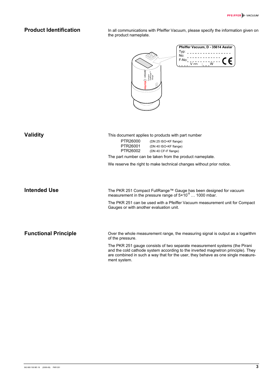
Product Identification
In all communications with Pfeiffer Vacuum, please specify the information given on
the product nameplate.
Pfeiffer Vacuum, D - 35614 Asslar
Typ:
No:
F-No:
V ; W
M
U
U
C
A
V
M
T
e
g
n
a
R
l
l
u
F
t
c
a
p
m
o
C
e
g
u
a
G
Validity
Intended Use
This document applies to products with part number
PTR26000
PTR26001
PTR26002
(DN 25 ISO-KF flange)
(DN 40 ISO-KF flange)
(DN 40 CF-F flange)
The part number can be taken from the product nameplate.
We reserve the right to make technical changes without prior notice.
The PKR 251 Compact FullRange™ Gauge has been designed for vacuum
measurement in the pressure range of 5×10⁻⁹ … 1000 mbar.
The PKR 251 can be used with a Pfeiffer Vacuum measurement unit for Compact
Gauges or with another evaluation unit.
Functional Principle
Over the whole measurement range, the measuring signal is output as a logarithm
of the pressure.
The PKR 251 gauge consists of two separate measurement systems (the Pirani
and the cold cathode system according to the inverted magnetron principle). They
are combined in such a way that for the user, they behave as one single measure-
ment system.
BG 805 155 BE / B (2005-08) PKR 251
3
�
1 Safety
1.1 Symbols Used
DANGER
Information on preventing any kind of physical injury.
WARNING
Information on preventing extensive equipment and environmental damage.
Caution
Information on correct handling or use. Disregard can lead to malfunctions or
minor equipment damage.
1.2 Personnel Qualifications
Skilled personnel
1.3 Safety Information
1.4 Liability and Warranty
All work described in this document may only be carried out by persons who
have suitable technical training and the necessary experience or who have been
instructed by the custodian of the product.
• Adhere to the applicable regulations and take the necessary precautions for the
process media used.
Consider possible reactions between the materials (→ 7) and the process
media.
Consider possible reactions of the process media due to the heat generated by
the product.
• Adhere to the applicable regulations and take the necessary precautions for all
work you are going to do and consider the safety information in this document.
• Before you begin to work, find out whether any vacuum components are con-
taminated. Adhere to the relevant regulations and take the necessary pre-
cautions when handling contaminated parts.
Pass on the safety information to other users.
Pfeiffer Vacuum assumes no liability and the warranty becomes null and void if the
custodian or third parties
• disregard the information in this document
• use the product in a non-conforming manner
• make any kind of changes (modifications, alterations etc.) to the product
• use the product with accessories not listed in the corresponding product
documentation.
The custodian assumes the responsibility in conjunction with the process media
used.
4
BG 805 155 BE / B (2005-08) PKR 251
�
2 Technical Data
Admissible temperatures
Storage
Operation
Bakeout
Relative humidity
Use
Measurement range (air, N2)
Accuracy
Reproducibility
Gas type dependence
Adjustment
Pirani measurement circuit
trimmer potentiometer
trimmer potentiometer
Cold cathode measurement circuit
-40 °C … +65 °C
+ 5 °C … +55 °C
+150 °C (without electronics unit and
magnetic shielding)
max. 80% at temperatures ≤+31 °C
decreasing to 50% at +40 °C
indoors only
altitude up to 2000 m (6600 ft)
5×10⁻⁹ … 1000 mbar
≈±30%
in the range 1×10⁻⁸ … 100 mbar
≈±5%
in the range 1×10⁻⁸ … 100 mbar
→ Appendix B
(→ 14)
at <1×10⁻⁴ mbar
(while depressing the pin)
at atmospheric pressure
no adjustment (the gauge is adjusted at
the factory and requires no main-
tenance)
Type of protection
Maximum pressure (absolute)
IP 40
10 bar
only for inert gases <55 °C
Supply
DANGER
The gauge may only be connected to supply or measurement units
that conform to the requirements of a grounded protective extra-low
voltage (SELV-E according to EN 61010). The connection to the
gauge has to be fused.1)
Voltage at the gauge
Power consumption
Fuse1)
15.0 … 30.0 VDC (max. ripple 1 Vpp)
≤2 W
≤1 AT
The minimum voltage of the power supply must be increased proportionally to the
length of the measuring cable.
Voltage at the supply unit with
maximum cable length
16.0 … 30.0 VDC (max. ripple 1 Vpp)
Electrical connection
Cable
Maximum cable length
Hirschmann compact connector
type GO 6, 6 pins, male
5 poles plus screening
75 m (0.25 mm² conductor)
100 m (0.34 mm² conductor)
300 m (1.0 mm² conductor)
BG 805 155 BE / B (2005-08) PKR 251
1) Pfeiffer Vacuum measurement and control units for Compact Gauges fulfill
these requirements.
5
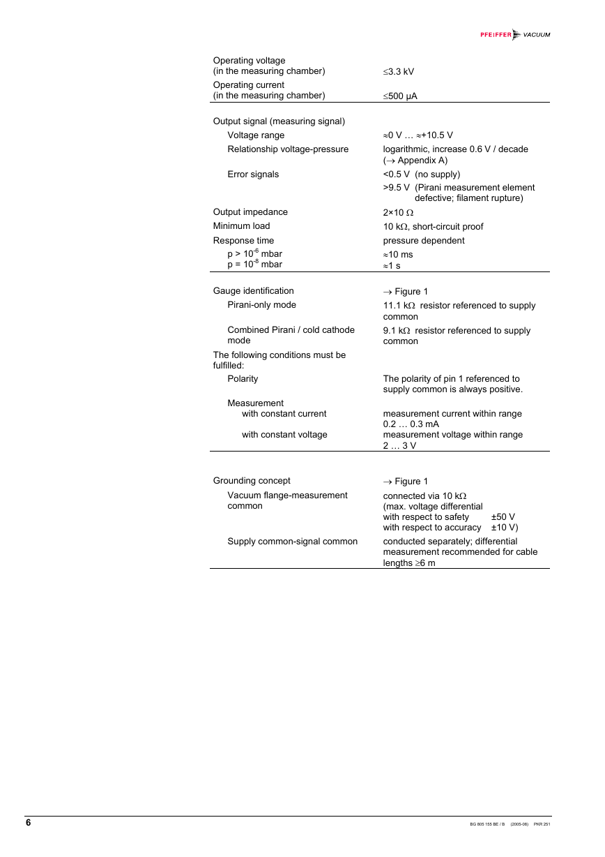
�Operating voltage
(in the measuring chamber)
Operating current
(in the measuring chamber)
Output signal (measuring signal)
Voltage range
Relationship voltage-pressure
Error signals
Output impedance
Minimum load
Response time
p > 10-6 mbar
p = 10-8 mbar
Gauge identification
Pirani-only mode
Combined Pirani / cold cathode
mode
The following conditions must be
fulfilled:
Polarity
Measurement
with constant current
with constant voltage
Grounding concept
Vacuum flange-measurement
common
Supply common-signal common
≤3.3 kV
≤500 µA
≈0 V … ≈+10.5 V
logarithmic, increase 0.6 V / decade
(→ Appendix A)
<0.5 V (no supply)
>9.5 V (Pirani measurement element
defective; filament rupture)
2×10 Ω
10 kΩ, short-circuit proof
pressure dependent
≈10 ms
≈1 s
→ Figure 1
11.1 kΩ resistor referenced to supply
common
9.1 kΩ resistor referenced to supply
common
The polarity of pin 1 referenced to
supply common is always positive.
measurement current within range
0.2 … 0.3 mA
measurement voltage within range
2 … 3 V
→ Figure 1
connected via 10 kΩ
(max. voltage differential
with respect to safety
±50 V
with respect to accuracy ±10 V)
conducted separately; differential
measurement recommended for cable
lengths ≥6 m
6
BG 805 155 BE / B (2005-08) PKR 251
�
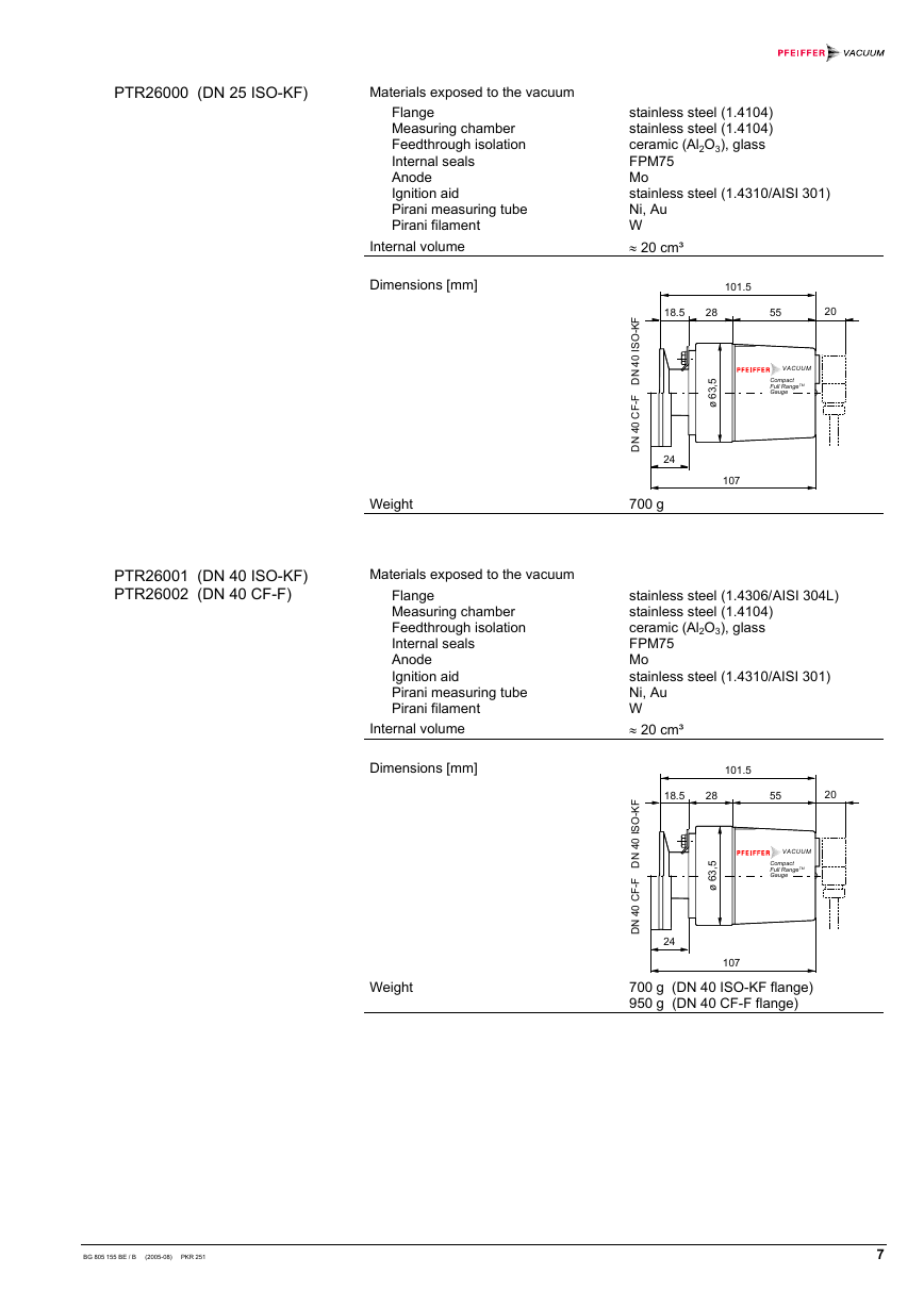
PTR26000 (DN 25 ISO-KF)
Materials exposed to the vacuum
Flange
Measuring chamber
Feedthrough isolation
Internal seals
Anode
Ignition aid
Pirani measuring tube
Pirani filament
Internal volume
Dimensions [mm]
stainless steel (1.4104)
stainless steel (1.4104)
ceramic (Al2O3), glass
FPM75
Mo
stainless steel (1.4310/AISI 301)
Ni, Au
W
≈ 20 cm³
101.5
18.5
28
55
20
-
F
K
O
S
I
0
4
N
D
F
-
F
C
0
4
N
D
VACUUM
Compact
Full RangeTM
Gauge
5
,
3
6
ø
24
107
PTR26001 (DN 40 ISO-KF)
PTR26002 (DN 40 CF-F)
Weight
700 g
Materials exposed to the vacuum
Flange
Measuring chamber
Feedthrough isolation
Internal seals
Anode
Ignition aid
Pirani measuring tube
Pirani filament
Internal volume
Dimensions [mm]
stainless steel (1.4306/AISI 304L)
stainless steel (1.4104)
ceramic (Al2O3), glass
FPM75
Mo
stainless steel (1.4310/AISI 301)
Ni, Au
W
≈ 20 cm³
101.5
18.5
28
55
20
-
F
K
O
S
I
0
4
N
D
F
-
F
C
0
4
N
D
VACUUM
Compact
Full RangeTM
Gauge
5
,
3
6
ø
24
107
Weight
700 g (DN 40 ISO-KF flange)
950 g (DN 40 CF-F flange)
BG 805 155 BE / B (2005-08) PKR 251
7
�
3 Installation
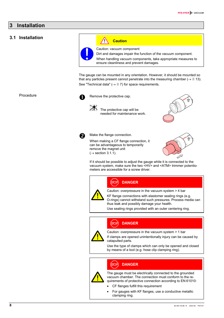
3.1 Installation
Caution
Caution: vacuum component
Dirt and damages impair the function of the vacuum component.
When handling vacuum components, take appropriate measures to
ensure cleanliness and prevent damages.
The gauge can be mounted in any orientation. However, it should be mounted so
that any particles present cannot penetrate into the measuring chamber (→ 13).
See "Technical data" (→ 7) for space requirements.
Procedure
Remove the protective cap.
The protective cap will be
needed for maintenance work.
Make the flange connection.
When making a CF flange connection, it
can be advantageous to temporarily
remove the magnet unit
(→ section 3.1.1).
If it should be possible to adjust the gauge while it is connected to the
vacuum system, make sure the two
and trimmer potentio-
meters are accessible for a screw driver.
DANGER
Caution: overpressure in the vacuum system > 4 bar
KF flange connections with elastomer sealing rings (e.g.
O-rings) cannot withstand such pressures. Process media can
thus leak and possibly damage your health.
Use sealing rings provided with an outer centering ring.
DANGER
Caution: overpressure in the vacuum system > 1 bar
If clamps are opened unintentionally injury can be caused by
catapulted parts.
Use the type of clamps which can only be opened and closed
by means of a tool (e.g. hose clip clamping ring).
DANGER
The gauge must be electrically connected to the grounded
vacuum chamber. The connection must conform to the re-
quirements of protective connection according to EN 61010:
• CF flanges fulfill this requirement
• For gauges with KF flanges, use a conductive metallic
clamping ring.
8
BG 805 155 BE / B (2005-08) PKR 251
�


 2023年江西萍乡中考道德与法治真题及答案.doc
 2012年重庆南川中考生物真题及答案.doc
 2013年江西师范大学地理学综合及文艺理论基础考研真题.doc
 2020年四川甘孜小升初语文真题及答案I卷.doc
 2020年注册岩土工程师专业基础考试真题及答案.doc
 2023-2024学年福建省厦门市九年级上学期数学月考试题及答案.doc
 2021-2022学年辽宁省沈阳市大东区九年级上学期语文期末试题及答案.doc
 2022-2023学年北京东城区初三第一学期物理期末试卷及答案.doc
 2018上半年江西教师资格初中地理学科知识与教学能力真题及答案.doc
 2012年河北国家公务员申论考试真题及答案-省级.doc
 2020-2021学年江苏省扬州市江都区邵樊片九年级上学期数学第一次质量检测试题及答案.doc
 2022下半年黑龙江教师资格证中学综合素质真题及答案.doc