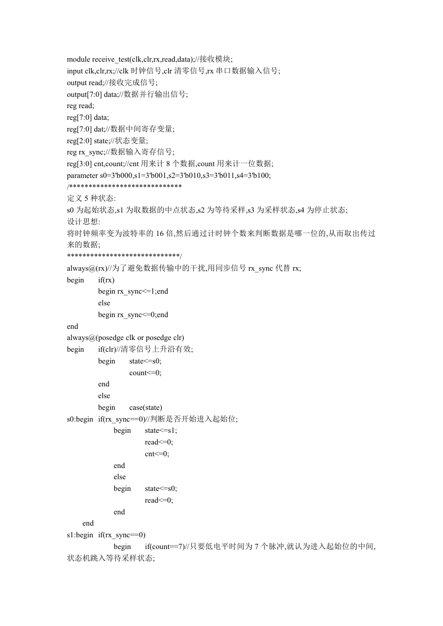
module receive_test(clk,clr,rx,read,data);//接收模块;
input clk,clr,rx;//clk 时钟信号,clr 清零信号,rx 串口数据输入信号;
output read;//接收完成信号;
output[7:0] data;//数据并行输出信号;
reg read;
reg[7:0] data;
reg[7:0] dat;//数据中间寄存变量;
reg[2:0] state;//状态变量;
reg rx_sync;//数据输入寄存信号;
reg[3:0] cnt,count;//cnt 用来计 8 个数据,count 用来计一位数据;
parameter s0=3'b000,s1=3'b001,s2=3'b010,s3=3'b011,s4=3'b100;
/*****************************
定义 5 种状态:
s0 为起始状态,s1 为取数据的中点状态,s2 为等待采样,s3 为采样状态,s4 为停止状态;
设计思想:
将时钟频率变为波特率的 16 倍,然后通过计时钟个数来判断数据是哪一位的,从而取出传过
来的数据;
*****************************/
always@(rx)//为了避免数据传输中的干扰,用同步信号 rx_sync 代替 rx;
begin
if(rx)
begin rx_sync<=1;end
else
begin rx_sync<=0;end
end
always@(posedge clk or posedge clr)
begin
if(clr)//清零信号上升沿有效;
begin
state<=s0;
count<=0;
end
else
begin
case(state)
s0:begin if(rx_sync==0)//判断是否开始进入起始位;
state<=s1;
read<=0;
cnt<=0;
state<=s0;
read<=0;
begin
end
else
begin
end
end
s1:begin if(rx_sync==0)
begin
if(count==7)//只要低电平时间为 7 个脉冲,就认为进入起始位的中间,
状态机跳入等待采样状态;
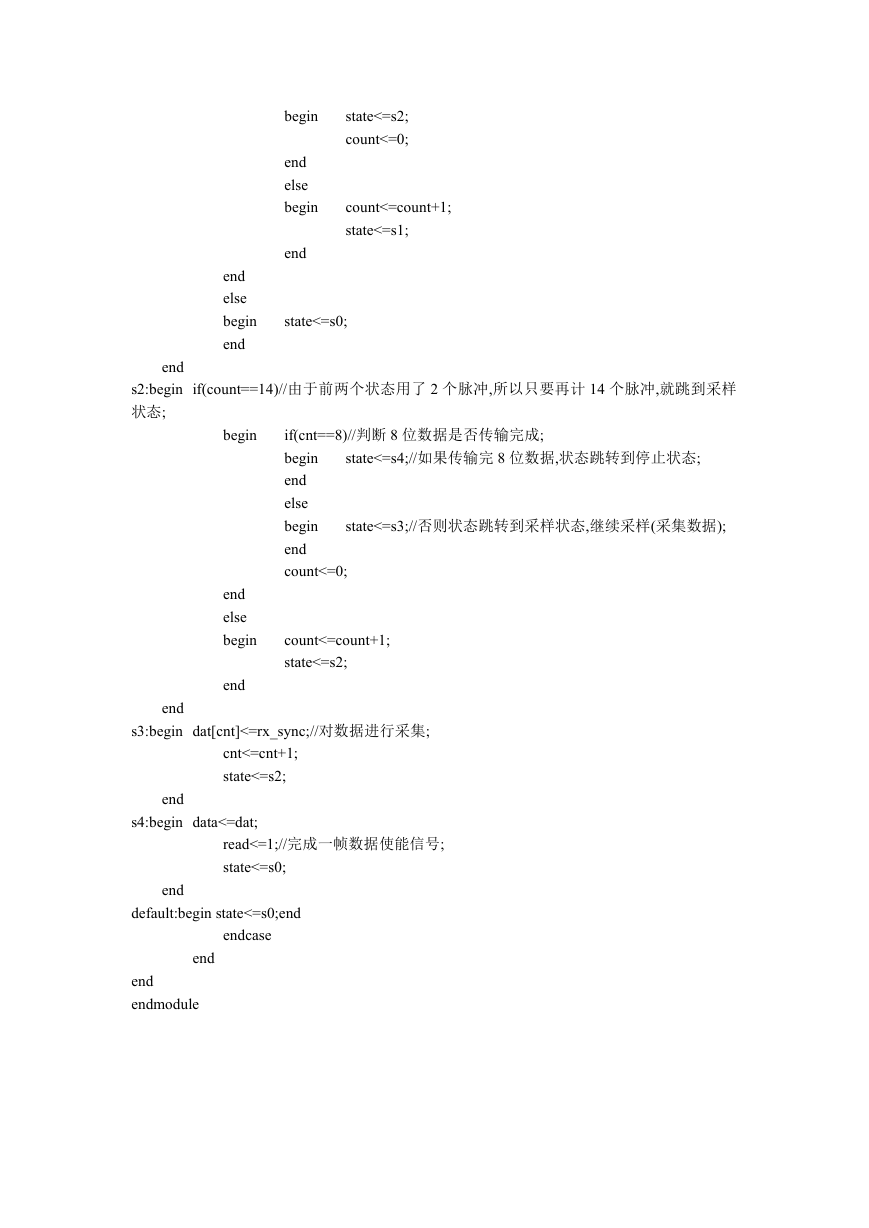
�
state<=s2;
count<=0;
count<=count+1;
state<=s1;
begin
end
else
begin
end
end
else
begin
end
state<=s0;
end
s2:begin if(count==14)//由于前两个状态用了 2 个脉冲,所以只要再计 14 个脉冲,就跳到采样
状态;
state<=s4;//如果传输完 8 位数据,状态跳转到停止状态;
if(cnt==8)//判断 8 位数据是否传输完成;
begin
end
else
begin
end
count<=0;
state<=s3;//否则状态跳转到采样状态,继续采样(采集数据);
begin
end
else
begin
end
count<=count+1;
state<=s2;
end
s3:begin dat[cnt]<=rx_sync;//对数据进行采集;
cnt<=cnt+1;
state<=s2;
end
s4:begin data<=dat;
read<=1;//完成一帧数据使能信号;
state<=s0;
end
default:begin state<=s0;end
endcase
end
end
endmodule
�


 2023年江西萍乡中考道德与法治真题及答案.doc
 2012年重庆南川中考生物真题及答案.doc
 2013年江西师范大学地理学综合及文艺理论基础考研真题.doc
 2020年四川甘孜小升初语文真题及答案I卷.doc
 2020年注册岩土工程师专业基础考试真题及答案.doc
 2023-2024学年福建省厦门市九年级上学期数学月考试题及答案.doc
 2021-2022学年辽宁省沈阳市大东区九年级上学期语文期末试题及答案.doc
 2022-2023学年北京东城区初三第一学期物理期末试卷及答案.doc
 2018上半年江西教师资格初中地理学科知识与教学能力真题及答案.doc
 2012年河北国家公务员申论考试真题及答案-省级.doc
 2020-2021学年江苏省扬州市江都区邵樊片九年级上学期数学第一次质量检测试题及答案.doc
 2022下半年黑龙江教师资格证中学综合素质真题及答案.doc