logo资料库

麦哲伦 GPS导航设备-A12 B12 AC12说明书.pdf

第1页 / 共176页
第2页 / 共176页
第3页 / 共176页
第4页 / 共176页
第5页 / 共176页
第6页 / 共176页
第7页 / 共176页
第8页 / 共176页
资料共176页,剩余部分请下载后查看
Chapter 1. General Information
Overview
Functional Description
Technical Specifications
Performance Specifications
Hardware Description
Physical Configuration
Power/Input/Output Connections
Interfaces to External Equipment
Power Requirements
Upgrades and Updates
Environmental Limitations
Antenna
Radio Interference
Chapter 2. Getting Started
General
Quick Start
Connection Procedures
Board
Serial Data Communication
Communication Port Setup
RTS/CTS Considerations
Data Output
Initial Operating Instructions
Chapter 3. Operation
System Setup
Message Format
Input Messages
Output Messages
Serial Port Configuration
Antenna Connection
Satellite Search Algorithm
Parameter Settings and Status
Saving New Parameter Settings
Position Modes
Altitude Hold Definition
Antenna Position Setting
NMEA Outputs
Differential Operation
General
SBAS Operation
Sources of Error
RTCM Messages
RTCM 104 Format, Version 2.2
Pulse Generation (1 PPS)
Magnetic Variation and Geoid Models
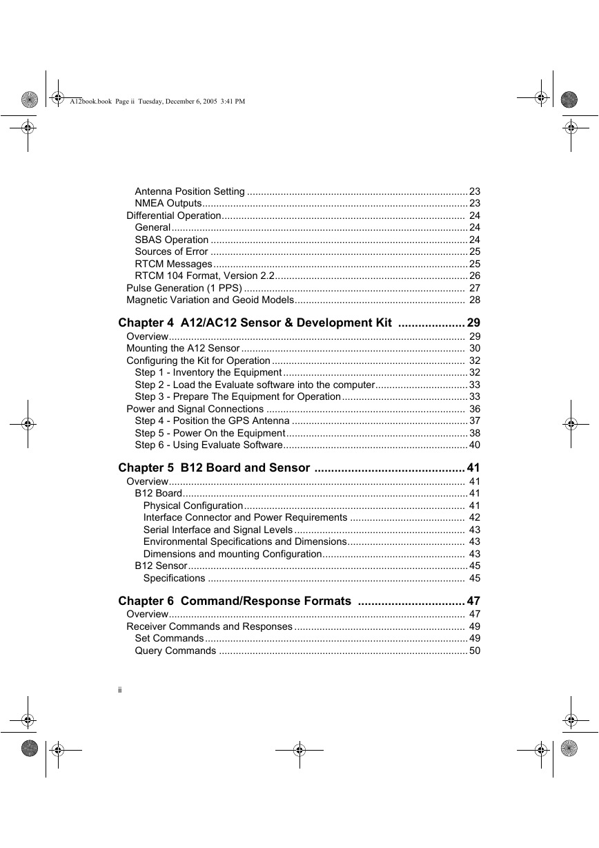
Chapter 4. A12/AC12 Sensor & Development Kit
Overview
Mounting the A12 Sensor
Configuring the Kit for Operation
Step 1 - Inventory the Equipment
Step 2 - Load the Evaluate software into the computer
Step 3 - Prepare The Equipment for Operation
Power and Signal Connections
Step 4 - Position the GPS Antenna
Step 5 - Power On the Equipment
Step 6 - Using Evaluate Software
Chapter 5. B12 Board and Sensor
Overview
B12 Board
Physical Configuration
Interface Connector and Power Requirements
Serial Interface and Signal Levels
Environmental Specifications and Dimensions
Dimensions and mounting Configuration
B12 Sensor
Specifications
Chapter 6. Command/Response Formats
Overview
Receiver Commands and Responses
Set Commands
Query Commands
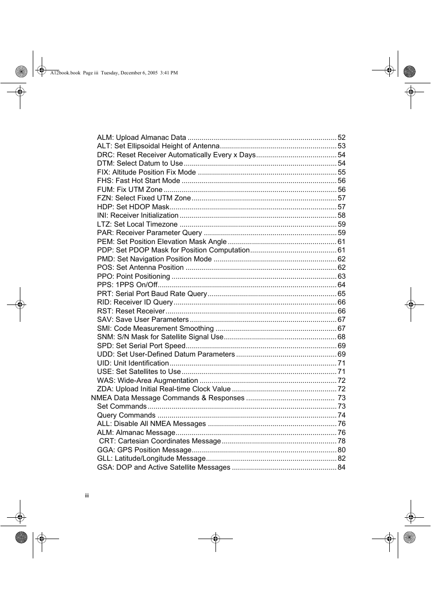
ALM: Upload Almanac Data
ALT: Set Ellipsoidal Height of Antenna
DRC: Reset Receiver Automatically Every x Days
DTM: Select Datum to Use
FIX: Altitude Position Fix Mode
FHS: Fast Hot Start Mode
FUM: Fix UTM Zone
FZN: Select Fixed UTM Zone
HDP: Set HDOP Mask
INI: Receiver Initialization
LTZ: Set Local Timezone
PAR: Receiver Parameter Query
PEM: Set Position Elevation Mask Angle
PDP: Set PDOP Mask for Position Computation
PMD: Set Navigation Position Mode
POS: Set Antenna Position
PPO: Point Positioning
PPS: 1PPS On/Off
PRT: Serial Port Baud Rate Query
RID: Receiver ID Query
RST: Reset Receiver
SAV: Save User Parameters
SMI: Code Measurement Smoothing
SNM: S/N Mask for Satellite Signal Use
SPD: Set Serial Port Speed
UDD: Set User-Defined Datum Parameters
UID: Unit Identification
USE: Set Satellites to Use
WAS: Wide-Area Augmentation
ZDA: Upload Initial Real-time Clock Value
NMEA Data Message Commands & Responses
Set Commands
Query Commands
ALL: Disable All NMEA Messages
ALM: Almanac Message
CRT: Cartesian Coordinates Message
GGA: GPS Position Message
GLL: Latitude/Longitude Message
GSA: DOP and Active Satellite Messages
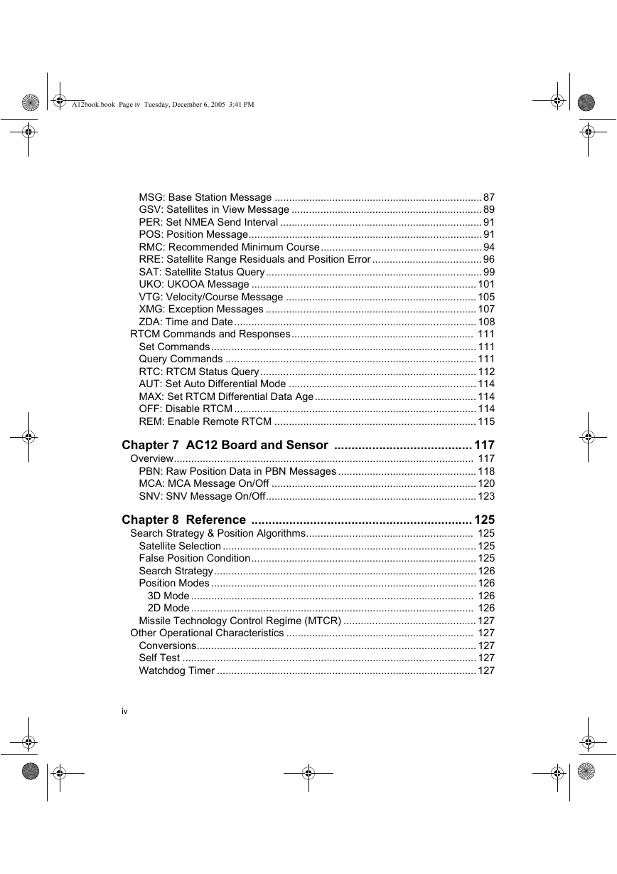
MSG: Base Station Message
GSV: Satellites in View Message
PER: Set NMEA Send Interval
POS: Position Message
RMC: Recommended Minimum Course
RRE: Satellite Range Residuals and Position Error
SAT: Satellite Status Query
UKO: UKOOA Message
VTG: Velocity/Course Message
XMG: Exception Messages
ZDA: Time and Date
RTCM Commands and Responses
Set Commands
Query Commands
RTC: RTCM Status Query
AUT: Set Auto Differential Mode
MAX: Set RTCM Differential Data Age
OFF: Disable RTCM
REM: Enable Remote RTCM
Chapter 7. AC12 Board and Sensor
Overview
PBN: Raw Position Data in PBN Messages
MCA: MCA Message On/Off
SNV: SNV Message On/Off
Chapter 8. Reference
Search Strategy & Position Algorithms
Satellite Selection
False Position Condition
Search Strategy
Position Modes
3D Mode
2D Mode
Missile Technology Control Regime (MTCR)
Other Operational Characteristics
Conversions
Self Test
Watchdog Timer
System Parameter Settings
Long-Term Operation
Datum Support
Detailed Performance Characteristics
Accuracy
TTFF (Time To First Fix)
Reacquisition Times
9. Troubleshooting
TTL-to-RS-232 Conversion
Port Setup
RTS/CTS
Factory Defaults
Saving Parameters
Logging Data
Using Third-Party Software
Appendix A. Global Product Support
Solutions for Common Problems
Corporate Web Page
Repair Centers
Appendix B. Supported Datums
Glossary
Index

A12™, B12™ & AC12™ REFERENCE MANUAL www.thalesgroup.com/navigation
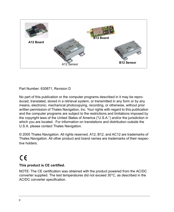
A12 Board B12 Board A12 Sensor B12 Sensor Part Number: 630871, Revision D No part of this publication or the computer programs described in it may be repro- duced, translated, stored in a retrieval system, or transmitted in any form or by any means, electronic, mechanical photocopying, recording, or otherwise, without prior written permission of Thales Navigation, Inc. Your rights with regard to this publication and the computer programs are subject to the restrictions and limitations imposed by the copyright laws of the United States of America (“U.S.A.”) and/or the jurisdiction in which you are located. For information on translations and distribution outside the U.S.A. please contact Thales Navigation. © 2005 Thales Navigation. All rights reserved. A12, B12, and AC12 are trademarks of Thales Navigation. All other product and brand names are trademarks of their respec- tive holders. This product is CE certified. NOTE: The CE certification was obtained with the product powered from the AC/DC converter supplied. The test temperatures did not exceed 30°C, as described in the AC/DC converter specification. II
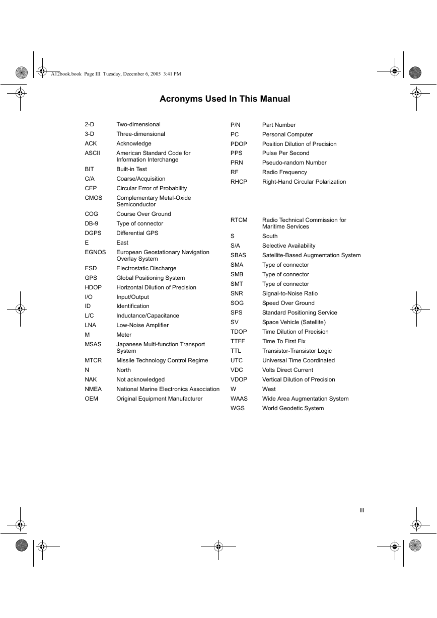
A12book.book Page III Tuesday, December 6, 2005 3:41 PM Acronyms Used In This Manual 2-D 3-D ACK ASCII BIT C/A CEP CMOS COG DB-9 DGPS E EGNOS ESD GPS HDOP I/O ID L/C LNA M MSAS MTCR N NAK NMEA OEM Two-dimensional Three-dimensional Acknowledge American Standard Code for Information Interchange Built-in Test Coarse/Acquisition Circular Error of Probability Complementary Metal-Oxide Semiconductor Course Over Ground Type of connector Differential GPS East European Geostationary Navigation Overlay System Electrostatic Discharge Global Positioning System Horizontal Dilution of Precision Input/Output Identification Inductance/Capacitance Low-Noise Amplifier Meter Japanese Multi-function Transport System Missile Technology Control Regime North Not acknowledged National Marine Electronics Association Original Equipment Manufacturer P/N PC PDOP PPS PRN RF RHCP RTCM S S/A SBAS SMA SMB SMT SNR SOG SPS SV TDOP TTFF TTL UTC VDC VDOP W WAAS WGS Part Number Personal Computer Position Dilution of Precision Pulse Per Second Pseudo-random Number Radio Frequency Right-Hand Circular Polarization Radio Technical Commission for Maritime Services South Selective Availability Satellite-Based Augmentation System Type of connector Type of connector Type of connector Signal-to-Noise Ratio Speed Over Ground Standard Positioning Service Space Vehicle (Satellite) Time Dilution of Precision Time To First Fix Transistor-Transistor Logic Universal Time Coordinated Volts Direct Current Vertical Dilution of Precision West Wide Area Augmentation System World Geodetic System III
A12book.book Page IV Tuesday, December 6, 2005 3:41 PM DISCLAIMER OF WARRANTIES AND LIMITATION OF LIABILITY LICENSOR AND ITS THIRD-PARTY SUPPLIERS MAKE NO WARRANTIES OR REPRESENTA- TIONS, EXPRESS OR IMPLIED, REGARDING THE PROGRAM, MEDIA, DOCUMENTATION, RESULTS OR ACCURACY OF DATA AND HEREBY EXPRESSLY DISCLAIM ANY WARRAN- TIES OF MERCHANTIBILITY AND FITNESS FOR A PARTICULAR PURPOSE AND NON- FRINGEMENT. LICENSOR AND ITS THIRD PARTY SUPPLIERS DO NOT WARRANT THE PROGRAM WILL MEET YOU REQUIREMENTS OR THAT ITS OPERATION WILL BE UNINTER- RUPTED OR ERROR-FREE. LICENSOR, its third-party suppliers, or anyone involved in the creation or delivery of the Program or Documentation to you shall have no liability to you or any third-party for special, incidental, indirect or consequential damages (including, but not limited to, loss of profits or savings, downtime, damage to or replacement of equipment or property, or recovery or replacement of programs or data) arising from claims based in warranty, contract, tort (including negligence), strict liability, or otherwise even if LICENSOR and its third-party have been advised of the possibility of such claim or damages. The liabil- ity of LICENSOR and its third-party suppliers for direct damages shall not exceed the actual amount paid for the program license. Some States do not allow the exclusion of limitation of implied warranties or liability for incidental or consequential damages, so the above limitations or exclusions may not apply to you. MANUAL DISCLAIMER THIS MANUAL IS PROVIDED “AS IS”; THALES NAVIGATION MAKES NO WARRANTIES TO ANY PERSON OR ENTITY WITH RESPECT TO THE SUBJECT MATTER OR USE OF INFORMA- TION CONTAINED HEREIN OR ANY DERIVATIVES THEREOF OR ANY SERVICES OR LICENSES. THALES NAVIGATION DISCLAIMS ALL IMPLIED WARRANTIES, INCLUDING, WITHOUT LIMITATION, WARRANTIES OF MERCHANTABILITY AND FITNESS FOR A PAR- TICULAR PURPOSE AND NONINFRINGEMENT. FURTHER, THALES NAVIGATION DOES NOT WARRANT, GUARANTEE, OR MAKE ANY REPRESENTATIONS REGARDING THE USE, OR THE RESULTS OF THE USE, OF THIS MANUAL IN TERMS OF CORRECTNESS, ACCURACY, RELIABILITY, OR OTHERWISE. THIS PUBLICATION AND FEATURES DESCRIBED HEREIN ARE SUBJECT TO CHANGE WITHOUT NOTICE. U.S. GOVERNMENT RESTRICTED RIGHTS The Program and Documentation are provided with RESTRICTIVE RIGHTS. Use, duplication, or dis- closure by the Government is subject to restrictions as set forth in subdivision (c)(1)(ii) of the Rights in Technical Data and Computer Software clause at DFARS 252.227-7013 or subdivision 9(c)(1) and (2) of the Commercial Computer Software - Restricted Rights 48 CFR 52.227.19, as applicable. Should you have any questions concerning the License Agreement or the Limited Warranties and Limita- tion of Liability, please contact THALES NAVIGATION in writing at the following address: 471 El Camino Real, Santa Clara, CA 95050-4300 IV
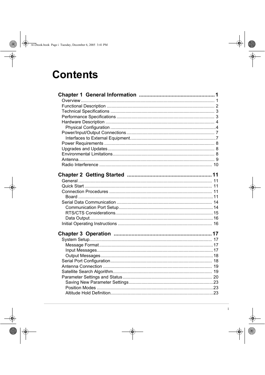
A12book.book Page i Tuesday, December 6, 2005 3:41 PM Contents Chapter 1 General Information ...................................................1 Overview............................................................................................................ 1 Functional Description ....................................................................................... 2 Technical Specifications .................................................................................... 3 Performance Specifications ............................................................................... 3 Hardware Description ........................................................................................ 4 Physical Configuration .....................................................................................4 Power/Input/Output Connections....................................................................... 7 Interfaces to External Equipment.....................................................................7 Power Requirements ......................................................................................... 8 Upgrades and Updates...................................................................................... 8 Environmental Limitations.................................................................................. 8 Antenna.............................................................................................................. 9 Radio Interference ........................................................................................... 10 Chapter 2 Getting Started .........................................................11 General ............................................................................................................ 11 Quick Start ....................................................................................................... 11 Connection Procedures ................................................................................... 11 Board .............................................................................................................11 Serial Data Communication ............................................................................. 14 Communication Port Setup............................................................................14 RTS/CTS Considerations...............................................................................15 Data Output....................................................................................................16 Initial Operating Instructions ............................................................................ 16 Chapter 3 Operation ..................................................................17 System Setup................................................................................................... 17 Message Format............................................................................................17 Input Messages..............................................................................................17 Output Messages...........................................................................................18 Serial Port Configuration.................................................................................. 18 Antenna Connection ........................................................................................ 19 Satellite Search Algorithm................................................................................ 19 Parameter Settings and Status........................................................................ 20 Saving New Parameter Settings....................................................................23 Position Modes ..............................................................................................23 Altitude Hold Definition...................................................................................23 R e l i a n c e F u n d a m e n t a l s i
A12book.book Page ii Tuesday, December 6, 2005 3:41 PM Antenna Position Setting ...............................................................................23 NMEA Outputs...............................................................................................23 Differential Operation....................................................................................... 24 General.......................................................................................................... 24 SBAS Operation ............................................................................................24 Sources of Error ............................................................................................25 RTCM Messages...........................................................................................25 RTCM 104 Format, Version 2.2.....................................................................26 Pulse Generation (1 PPS) ............................................................................... 27 Magnetic Variation and Geoid Models............................................................. 28 Chapter 4 A12/AC12 Sensor & Development Kit .................... 29 Overview.......................................................................................................... 29 Mounting the A12 Sensor ................................................................................ 30 Configuring the Kit for Operation ..................................................................... 32 Step 1 - Inventory the Equipment ..................................................................32 Step 2 - Load the Evaluate software into the computer.................................33 Step 3 - Prepare The Equipment for Operation............................................. 33 Power and Signal Connections ....................................................................... 36 Step 4 - Position the GPS Antenna ...............................................................37 Step 5 - Power On the Equipment.................................................................38 Step 6 - Using Evaluate Software..................................................................40 Chapter 5 B12 Board and Sensor ............................................. 41 Overview.......................................................................................................... 41 B12 Board......................................................................................................41 Physical Configuration............................................................................... 41 Interface Connector and Power Requirements ......................................... 42 Serial Interface and Signal Levels ............................................................. 43 Environmental Specifications and Dimensions.......................................... 43 Dimensions and mounting Configuration................................................... 43 B12 Sensor.................................................................................................... 45 Specifications ............................................................................................ 45 Chapter 6 Command/Response Formats ................................ 47 Overview.......................................................................................................... 47 Receiver Commands and Responses ............................................................. 49 Set Commands..............................................................................................49 Query Commands .........................................................................................50 ii
A12book.book Page iii Tuesday, December 6, 2005 3:41 PM ALM: Upload Almanac Data .......................................................................... 52 ALT: Set Ellipsoidal Height of Antenna.......................................................... 53 DRC: Reset Receiver Automatically Every x Days........................................54 DTM: Select Datum to Use............................................................................54 FIX: Altitude Position Fix Mode .....................................................................55 FHS: Fast Hot Start Mode ............................................................................. 56 FUM: Fix UTM Zone ...................................................................................... 56 FZN: Select Fixed UTM Zone........................................................................57 HDP: Set HDOP Mask................................................................................... 57 INI: Receiver Initialization ..............................................................................58 LTZ: Set Local Timezone ..............................................................................59 PAR: Receiver Parameter Query ..................................................................59 PEM: Set Position Elevation Mask Angle ...................................................... 61 PDP: Set PDOP Mask for Position Computation...........................................61 PMD: Set Navigation Position Mode ............................................................. 62 POS: Set Antenna Position ...........................................................................62 PPO: Point Positioning ..................................................................................63 PPS: 1PPS On/Off.........................................................................................64 PRT: Serial Port Baud Rate Query................................................................ 65 RID: Receiver ID Query.................................................................................66 RST: Reset Receiver.....................................................................................66 SAV: Save User Parameters ......................................................................... 67 SMI: Code Measurement Smoothing ............................................................67 SNM: S/N Mask for Satellite Signal Use........................................................68 SPD: Set Serial Port Speed...........................................................................69 UDD: Set User-Defined Datum Parameters ..................................................69 UID: Unit Identification................................................................................... 71 USE: Set Satellites to Use............................................................................. 71 WAS: Wide-Area Augmentation ....................................................................72 ZDA: Upload Initial Real-time Clock Value ....................................................72 NMEA Data Message Commands & Responses ............................................ 73 Set Commands..............................................................................................73 Query Commands .........................................................................................74 ALL: Disable All NMEA Messages ................................................................ 76 ALM: Almanac Message................................................................................ 76 CRT: Cartesian Coordinates Message......................................................... 78 GGA: GPS Position Message........................................................................80 GLL: Latitude/Longitude Message.................................................................82 GSA: DOP and Active Satellite Messages ....................................................84 iii
A12book.book Page iv Tuesday, December 6, 2005 3:41 PM MSG: Base Station Message ........................................................................87 GSV: Satellites in View Message ..................................................................89 PER: Set NMEA Send Interval ...................................................................... 91 POS: Position Message.................................................................................91 RMC: Recommended Minimum Course........................................................94 RRE: Satellite Range Residuals and Position Error ...................................... 96 SAT: Satellite Status Query...........................................................................99 UKO: UKOOA Message .............................................................................. 101 VTG: Velocity/Course Message ..................................................................105 XMG: Exception Messages .........................................................................107 ZDA: Time and Date.................................................................................... 108 RTCM Commands and Responses............................................................... 111 Set Commands............................................................................................111 Query Commands .......................................................................................111 RTC: RTCM Status Query........................................................................... 112 AUT: Set Auto Differential Mode ................................................................. 114 MAX: Set RTCM Differential Data Age........................................................ 114 OFF: Disable RTCM .................................................................................... 114 REM: Enable Remote RTCM ......................................................................115 Chapter 7 AC12 Board and Sensor ........................................ 117 Overview........................................................................................................ 117 PBN: Raw Position Data in PBN Messages ................................................118 MCA: MCA Message On/Off ....................................................................... 120 SNV: SNV Message On/Off.........................................................................123 Chapter 8 Reference ................................................................ 125 Search Strategy & Position Algorithms.......................................................... 125 Satellite Selection ........................................................................................ 125 False Position Condition.............................................................................. 125 Search Strategy........................................................................................... 126 Position Modes ............................................................................................126 3D Mode .................................................................................................. 126 2D Mode .................................................................................................. 126 Missile Technology Control Regime (MTCR) .............................................. 127 Other Operational Characteristics ................................................................. 127 Conversions................................................................................................. 127 Self Test ......................................................................................................127 Watchdog Timer ..........................................................................................127 iv
分享到:
收藏