PCM510xA具具有有 PLL 和和 32 位位、、384kHz PCM 接接口口的的 2.1 VRMS、、
112/106/100dB 音音频频立立体体声声 DAC
PCM5100A, PCM5101A, PCM5102A
PCM5100A-Q1, PCM5101A-Q1, PCM5102A-Q1
ZHCSA60C –MAY 2012–REVISED MAY 2015
1 特特性性
1• 超低带外噪声
• 具有 BCK 基准的高性能集成音频锁相环 (PLL),可
在内部生成 SCK
• 直接线路电平 2.1 VRMS 输出
• 无需隔直电容
• 线路电平输出支持低至 1kΩ 的负载
• 智能静音系统;软斜升或斜降搭配模拟静音,实现
120dB 静音信噪比 (SNR)
• 接收 16、24 和 32 位音频数据
• PCM 数据样式:I2S,左对齐
• 当 LRCK 和 BCK 被置为无效时,自动进入省电模
•
式
1.8V 或3.3V 故障安全低压 CMOS (LVCMOS) 数
字输入
• 采用硬件引脚的简易配置
• 单电源供电:14
– 3.3V 模拟电源、1.8V 或3.3V 数字电源
• 符合 AEC-Q100 标准
2 应应用用
• A/V 接收器、DVD、BD 播放器
• 汽车信息娱乐系统和远程信息处理
• HDTV 接收器
• 汽车售后加装放大器
3 说说明明
PCM510xA 器件属于单片 CMOS 集成电路系列,由立
体声数模转换器 (DAC) 和采用薄型小外形尺寸
(TSSOP) 封装的附加支持电路组成。PCM510xA 器件
使用 TI 最新一代高级分段 DAC 架构产品,可实现出
色的动态性能并提升针对时钟抖动的耐受度。
凭借 DirectPath™电荷泵技术,PCM510xA 器件提供
2.1 VRMS 中央接地输出(设计人员无需在输出上连接
隔直电容)以及传统意义上与单电源线路驱动器相关的
外部静音电路。
集成线路驱动器的每个引脚支持低至 1kΩ 的负载,从
而在性能上超过其他所有基于电荷泵的线路驱动器。
器件上集成的 PLL 免除了对于系统时钟(通常称为主
时钟)的需要,从而实现一个 3 线制 I2C 连接并减少
了系统电磁干扰 (EMI)。
智能时钟误差与 PowerSense 欠压保护采用双层系
统,能够消除喀嗒和噼啪声。
相比许多传统的开关电容 DAC 架构,PCM510xA 系
列能够将带外噪声控制在 20dB 的较低水平,从而减少
下游放大器/ADC 中的 EMI 和混叠(在 100kHz(OBN
典型值)到 3MHz 之间测得)。
表表 1. 器器件件信信息息(1)
器器件件型型号号
封封装装
封封装装尺尺寸寸((标标称称值值))
PCM5102A
PCM5101A
PCM5100A
(1) 要了解所有可用封装,请见数据表末尾的可订购产品附录。
5.50mm x 4.40mm
TSSOP (20)
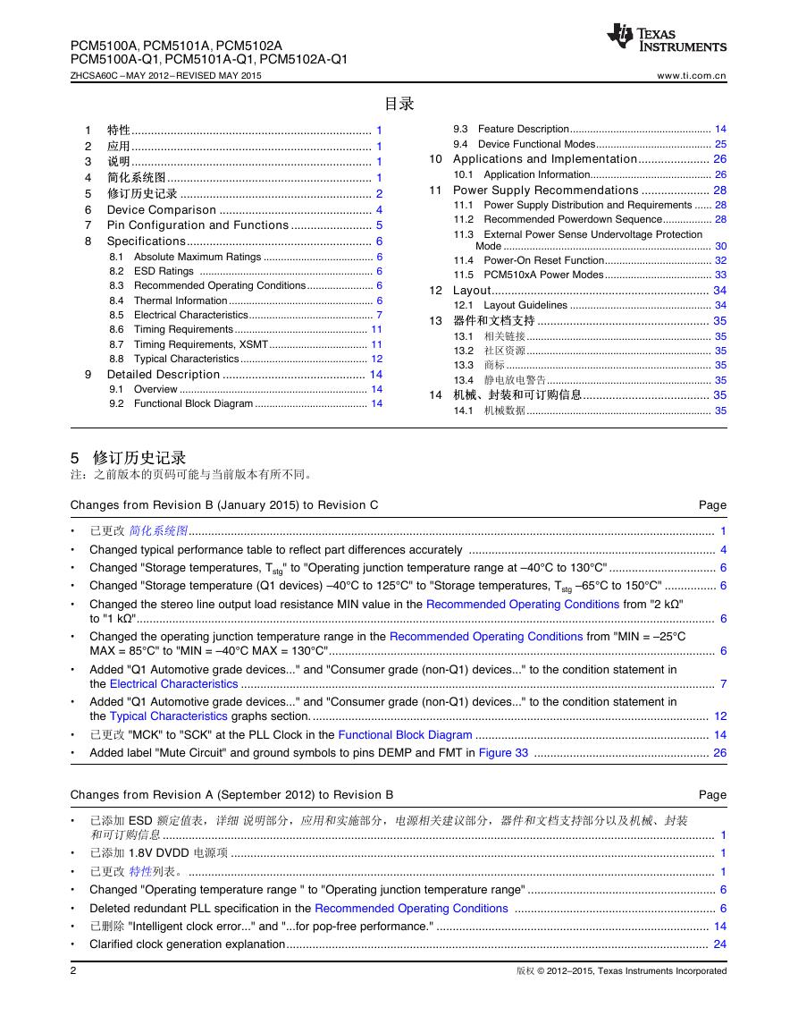
4 简简化化系系统统图图
中的器件编号“PCM510x”至“PCM510xA”
1
An IMPORTANT NOTICE at the end of this data sheet addresses availability, warranty, changes, use in safety-critical applications,
intellectual property matters and other important disclaimers. PRODUCTION DATA.
English Data Sheet: SLAS859
MICINBTModulePCM1863/5I2SBCKAUXIN2ch Single EndedAnalogSensor-Light Intensity-Ultrasonic-Battery LevelLRCK2ch Single EndedMSP430WiLAN chipLINEOUTPCM510xAPLLCharge PumpProductFolderSample &BuyTechnicalDocumentsTools &SoftwareSupport &Community�
PCM5100A, PCM5101A, PCM5102A
PCM5100A-Q1, PCM5101A-Q1, PCM5102A-Q1
ZHCSA60C –MAY 2012–REVISED MAY 2015
目目录录
1 特特性性.......................................................................... 1
2 应应用用.......................................................................... 1
3 说说明明.......................................................................... 1
4 简简化化系系统统图图............................................................... 1
5 修修订订历历史史记记录录 ........................................................... 2
6 Device Comparison ............................................... 4
7 Pin Configuration and Functions ......................... 5
8 Specifications......................................................... 6
8.1 Absolute Maximum Ratings ...................................... 6
8.2 ESD Ratings ............................................................ 6
8.3 Recommended Operating Conditions....................... 6
8.4 Thermal Information.................................................. 6
8.5 Electrical Characteristics........................................... 7
8.6 Timing Requirements.............................................. 11
8.7 Timing Requirements, XSMT.................................. 11
8.8 Typical Characteristics............................................ 12
9 Detailed Description ............................................ 14
9.1 Overview ................................................................. 14
9.2 Functional Block Diagram ....................................... 14
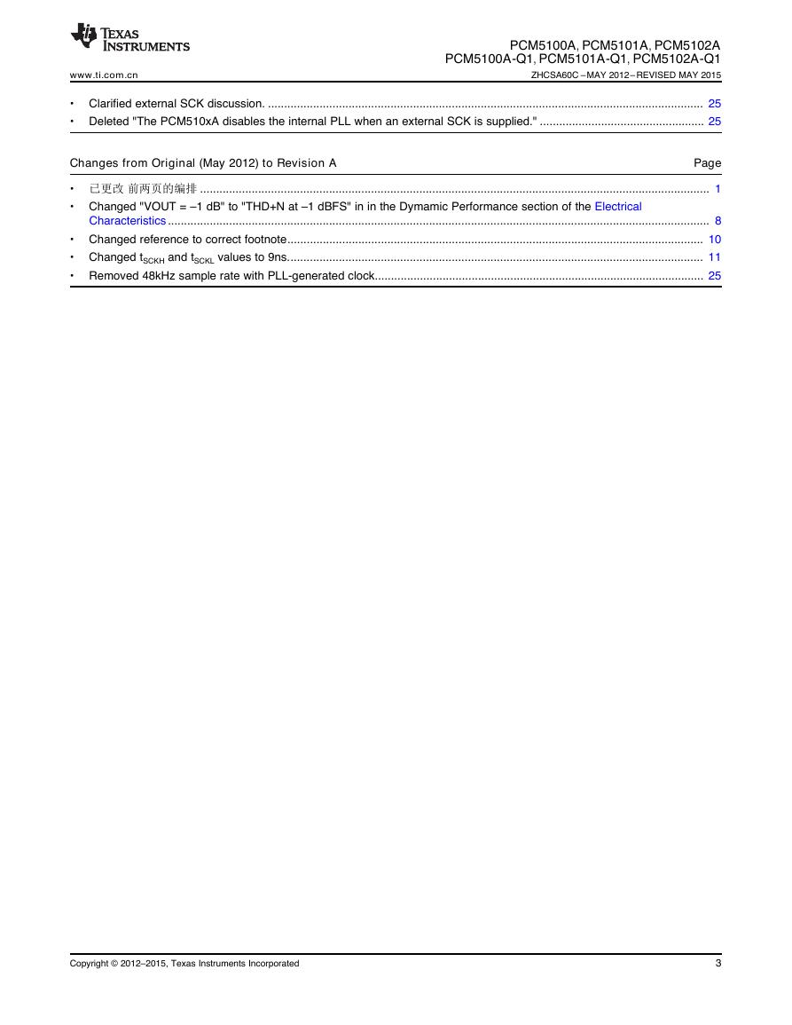
5 修修订订历历史史记记录录
注:之前版本的页码可能与当前版本有所不同。
www.ti.com.cn
9.3 Feature Description................................................. 14
9.4 Device Functional Modes........................................ 25
10 Applications and Implementation...................... 26
10.1 Application Information.......................................... 26
11 Power Supply Recommendations ..................... 28
11.1 Power Supply Distribution and Requirements ...... 28
11.2 Recommended Powerdown Sequence................. 28
11.3 External Power Sense Undervoltage Protection
Mode ........................................................................ 30
11.4 Power-On Reset Function..................................... 32
11.5 PCM510xA Power Modes..................................... 33
12 Layout................................................................... 34
12.1 Layout Guidelines ................................................. 34
13 器器件件和和文文档档支支持持 ..................................................... 35
13.1 相关链接................................................................ 35
13.2 社区资源................................................................ 35
13.3 商标 ....................................................................... 35
13.4 静电放电警告......................................................... 35
14 机机械械、、封封装装和和可可订订购购信信息息....................................... 35
14.1 机械数据................................................................ 35
Changes from Revision B (January 2015) to Revision C
Page
• 已更改 简化系统图.................................................................................................................................................................. 1
• Changed typical performance table to reflect part differences accurately ............................................................................ 4
• Changed "Storage temperatures, Tstg" to "Operating junction temperature range at –40°C to 130°C" ................................. 6
• Changed "Storage temperature (Q1 devices) –40°C to 125°C" to "Storage temperatures, Tstg –65°C to 150°C" ................ 6
• Changed the stereo line output load resistance MIN value in the Recommended Operating Conditions from "2 kΩ"
to "1 kΩ".................................................................................................................................................................................. 6
• Changed the operating junction temperature range in the Recommended Operating Conditions from "MIN = –25°C
MAX = 85°C" to "MIN = –40°C MAX = 130°C"....................................................................................................................... 6
• Added "Q1 Automotive grade devices..." and "Consumer grade (non-Q1) devices..." to the condition statement in
the Electrical Characteristics .................................................................................................................................................. 7
• Added "Q1 Automotive grade devices..." and "Consumer grade (non-Q1) devices..." to the condition statement in
the Typical Characteristics graphs section........................................................................................................................... 12
• 已更改 "MCK" to "SCK" at the PLL Clock in the Functional Block Diagram ........................................................................ 14
• Added label "Mute Circuit" and ground symbols to pins DEMP and FMT in Figure 33 ...................................................... 26
Changes from Revision A (September 2012) to Revision B
Page
• 已添加 ESD 额定值表,详细 说明部分,应用和实施部分,电源相关建议部分,器件和文档支持部分以及机械、封装
和可订购信息.......................................................................................................................................................................... 1
• 已添加 1.8V DVDD 电源项 ..................................................................................................................................................... 1
• 已更改 特性列表。.................................................................................................................................................................. 1
• Changed "Operating temperature range " to "Operating junction temperature range" .......................................................... 6
• Deleted redundant PLL specification in the Recommended Operating Conditions .............................................................. 6
• 已删除 "Intelligent clock error..." and "...for pop-free performance." .................................................................................... 14
• Clarified clock generation explanation.................................................................................................................................. 24
2
版权 © 2012–2015, Texas Instruments Incorporated
�
www.ti.com.cn
PCM5100A, PCM5101A, PCM5102A
PCM5100A-Q1, PCM5101A-Q1, PCM5102A-Q1
ZHCSA60C –MAY 2012–REVISED MAY 2015
• Clarified external SCK discussion. ....................................................................................................................................... 25
• Deleted "The PCM510xA disables the internal PLL when an external SCK is supplied." ................................................... 25
Changes from Original (May 2012) to Revision A
Page
• 已更改 前两页的编排 .............................................................................................................................................................. 1
• Changed "VOUT = –1 dB" to "THD+N at –1 dBFS" in in the Dymamic Performance section of the Electrical
Characteristics ........................................................................................................................................................................ 8
• Changed reference to correct footnote................................................................................................................................. 10
• Changed tSCKH and tSCKL values to 9ns................................................................................................................................. 11
• Removed 48kHz sample rate with PLL-generated clock...................................................................................................... 25
Copyright © 2012–2015, Texas Instruments Incorporated
3
�
PCM5100A, PCM5101A, PCM5102A
PCM5100A-Q1, PCM5101A-Q1, PCM5102A-Q1
ZHCSA60C –MAY 2012–REVISED MAY 2015
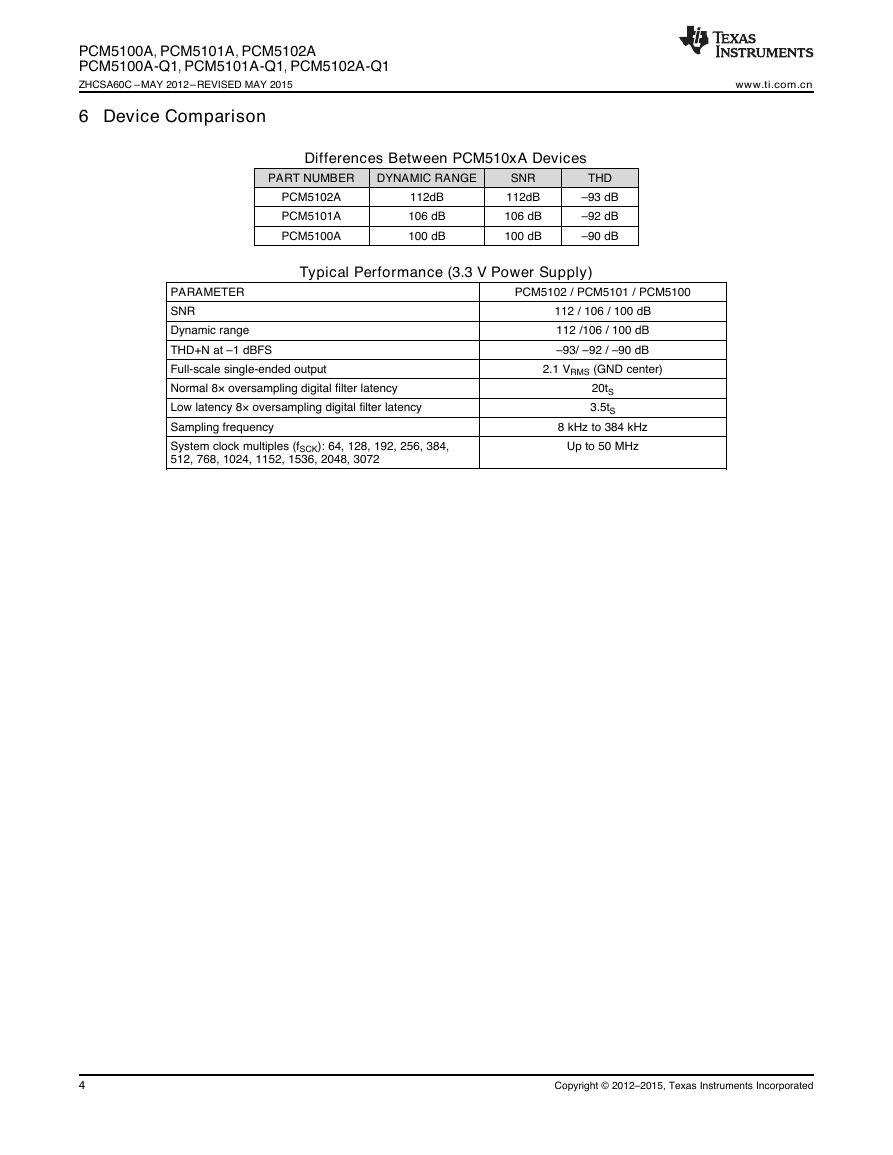
6 Device Comparison
www.ti.com.cn
Differences Between PCM510xA Devices
PART NUMBER
DYNAMIC RANGE
PCM5102A
PCM5101A
PCM5100A
112dB
106 dB
100 dB
SNR
112dB
106 dB
100 dB
THD
–93 dB
–92 dB
–90 dB
Typical Performance (3.3 V Power Supply)
PARAMETER
SNR
Dynamic range
THD+N at –1 dBFS
Full-scale single-ended output
Normal 8× oversampling digital filter latency
Low latency 8× oversampling digital filter latency
Sampling frequency
System clock multiples (fSCK): 64, 128, 192, 256, 384,
512, 768, 1024, 1152, 1536, 2048, 3072
PCM5102 / PCM5101 / PCM5100
112 / 106 / 100 dB
112 /106 / 100 dB
–93/ –92 / –90 dB
2.1 VRMS (GND center)
20tS
3.5tS
8 kHz to 384 kHz
Up to 50 MHz
4
Copyright © 2012–2015, Texas Instruments Incorporated
�
www.ti.com.cn
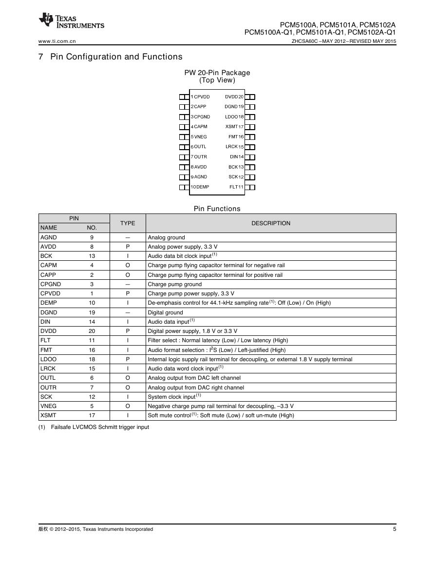
7 Pin Configuration and Functions
PCM5100A, PCM5101A, PCM5102A
PCM5100A-Q1, PCM5101A-Q1, PCM5102A-Q1
ZHCSA60C –MAY 2012–REVISED MAY 2015
PW 20-Pin Package
(Top View)
NAME
AGND
AVDD
BCK
CAPM
CAPP
CPGND
CPVDD
DEMP
DGND
DIN
DVDD
FLT
FMT
LDOO
LRCK
OUTL
OUTR
SCK
VNEG
XSMT
PIN
NO.
9
8
13
4
2
3
1
10
19
14
20
11
16
18
15
6
7
12
5
17
Pin Functions
TYPE
DESCRIPTION
—
P
I
O
O
—
P
I
—
I
P
I
I
P
I
O
O
I
O
I
Analog ground
Analog power supply, 3.3 V
Audio data bit clock input(1)
Charge pump flying capacitor terminal for negative rail
Charge pump flying capacitor terminal for positive rail
Charge pump ground
Charge pump power supply, 3.3 V
De-emphasis control for 44.1-kHz sampling rate(1): Off (Low) / On (High)
Digital ground
Audio data input(1)
Digital power supply, 1.8 V or 3.3 V
Filter select : Normal latency (Low) / Low latency (High)
Audio format selection : I2S (Low) / Left-justified (High)
Internal logic supply rail terminal for decoupling, or external 1.8 V supply terminal
Audio data word clock input(1)
Analog output from DAC left channel
Analog output from DAC right channel
System clock input(1)
Negative charge pump rail terminal for decoupling, –3.3 V
Soft mute control(1): Soft mute (Low) / soft un-mute (High)
(1) Failsafe LVCMOS Schmitt trigger input
版权 © 2012–2015, Texas Instruments Incorporated
5
�
PCM5100A, PCM5101A, PCM5102A
PCM5100A-Q1, PCM5101A-Q1, PCM5102A-Q1
ZHCSA60C –MAY 2012–REVISED MAY 2015
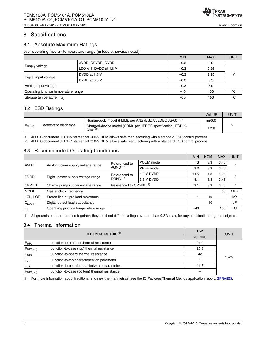
8 Specifications
8.1 Absolute Maximum Ratings
over operating free-air temperature range (unless otherwise noted)
Supply voltage
Digital input voltage
AVDD, CPVDD, DVDD
LDO with DVDD at 1.8 V
DVDD at 1.8 V
DVDD at 3.3 V
Analog input voltage
Operating junction temperature range
Storage temperature, Tstg
8.2 ESD Ratings
MIN
–0.3
–0.3
–0.3
–0.3
–0.3
–40
–65
V(ESD)
Electrostatic discharge
Human-body model (HBM), per ANSI/ESDA/JEDEC JS-001(1)
Charged-device model (CDM), per JEDEC specification JESD22-
C101(2)
www.ti.com.cn
MAX
3.9
2.25
2.25
3.9
3.9
130
150
VALUE
±2000
±750
UNIT
V
°C
°C
UNIT
V
(1)
(2)
JEDEC document JEP155 states that 500-V HBM allows safe manufacturing with a standard ESD control process.
JEDEC document JEP157 states that 250-V CDM allows safe manufacturing with a standard ESD control process.
8.3 Recommended Operating Conditions
AVDD
Analog power supply voltage range
Referenced to
AGND(1)
DVDD
Digital power supply voltage range
VCOM mode
VREF mode
1.8 V DVDD
3.3 V DVDD
Referenced to
DGND(1)
Referenced to CPGND(1)
MIN
3
3.2
1.65
3.1
3.1
NOM MAX UNIT
3.3
3.3
1.8
3.3
3.3
3.46
3.46
1.95
3.46
3.46
V
V
V
CPVDD
MCLK
LOL, LOR
CLOUT
TJ
(1) All grounds on board are tied together; they must not differ in voltage by more than 0.2 V max, for any combination of ground signals.
Charge pump supply voltage range
Master clock frequency
Stereo line output load resistance
Digital output load capacitance
Operating junction temperature range
50 MHz
kΩ
pF
°C
10
10
130
1
–40
8.4 Thermal Information
THERMAL METRIC(1)
PW
20 PINS
UNIT
RθJA
RθJC(top)
RθJB
ψJT
ψJB
RθJC(bot)
(1) For more information about traditional and new thermal metrics, see the IC Package Thermal Metrics application report, SPRA953.
Junction-to-ambient thermal resistance
Junction-to-case (top) thermal resistance
Junction-to-board thermal resistance
Junction-to-top characterization parameter
Junction-to-board characterization parameter
Junction-to-case (bottom) thermal resistance
91.2
25.3
42
1
41.5
—
°C/W
6
Copyright © 2012–2015, Texas Instruments Incorporated
�
www.ti.com.cn
PCM5100A, PCM5101A, PCM5102A
PCM5100A-Q1, PCM5101A-Q1, PCM5102A-Q1
ZHCSA60C –MAY 2012–REVISED MAY 2015
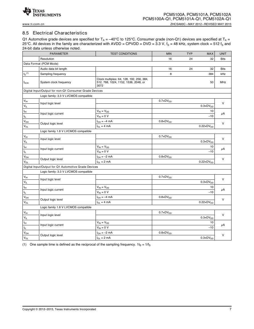
8.5 Electrical Characteristics
Q1 Automotive grade devices are specified for TA = –40°C to 125°C. Consumer grade (non-Q1) devices are specified at TA =
25°C. All devices in the family are characterized with AVDD = CPVDD = DVD = 3.3 V, fS = 48 kHz, system clock = 512 fS and
24-bit data unless otherwise noted.
PARAMETER
TEST CONDITIONS
Resolution
Data Format (PCM Mode)
(1)
fS
Audio data bit length
Sampling frequency
fSCK
Clock multiples: 64, 128, 192, 256, 384,
512, 768, 1024, 1152, 1536, 2048, or
3072
Digital Input/Output for non-Q1 Consumer Grade Devices
System clock frequency
Logic family: 3.3 V LVCMOS compatible
VIH
VIL
IIH
IIL
VOH
VOL
Input logic level
Input logic current
Output logic level
Logic family 1.8 V LVCMOS compatible
VIN = VDD
VIN = 0 V
IOH = –4 mA
IOL = 4 mA
Input logic level
VIH
VIL
IIH
IIL
VOH
VOL
Digital Input/Output for Q1 Automotive Grade Devices
Input logic current
Output logic level
VIN = VDD
VIN = 0 V
IOH = –2 mA
IOL = 2 mA
Logic family: 3.3 V LVCMOS compatible
VIH
VIL
IIH
IIL
VOH
VOL
Input logic level
Input logic current
Output logic level
Logic family 1.8 V LVCMOS compatible
VIN = VDD
VIN = 0 V
IOH = –4 mA
IOL = 4 mA
Input logic level
Input logic current
VIH
VIL
IIH
IIL
VOH
VOL
(1) One sample time is defined as the reciprocal of the sampling frequency. 1tS = 1/fS
VIN = VDD
VIN = 0 V
IOH = –2 mA
IOL = 2 mA
Output logic level
MIN
16
16
8
TYP
24
24
MAX
32
32
384
UNIT
Bits
Bits
kHz
50
MHz
0.7×DVDD
0.8×DVDD
0.7×DVDD
0.8×DVDD
0.7×DVDD
0.8×DVDD
0.7×DVDD
0.8×DVDD
0.3×DVDD
10
–10
0.22×DVDD
0.3×DVDD
10
–10
0.22×DVDD
0.3×DVDD
10
–10
0.22×DVDD
0.3×DVDD
10
–10
0.3×DVDD
V
µA
V
V
µA
V
V
µA
V
V
µA
V
Copyright © 2012–2015, Texas Instruments Incorporated
7
�
PCM5100A, PCM5101A, PCM5102A
PCM5100A-Q1, PCM5101A-Q1, PCM5102A-Q1
ZHCSA60C –MAY 2012–REVISED MAY 2015
www.ti.com.cn
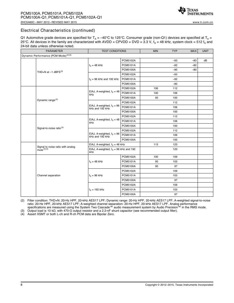
Electrical Characteristics (continued)
Q1 Automotive grade devices are specified for TA = –40°C to 125°C. Consumer grade (non-Q1) devices are specified at TA =
25°C. All devices in the family are characterized with AVDD = CPVDD = DVD = 3.3 V, fS = 48 kHz, system clock = 512 fS and
24-bit data unless otherwise noted.
PARAMETER
TEST CONDITIONS
MIN
TYP
MAX
UNIT
Dynamic Performance (PCM Mode)(2)(3)
dB
–83
–82
–80
THD+N at –1 dBFS(3)
Dynamic range(3)
Signal-to-noise ratio(3)
fS = 48 kHz
fS = 96 kHz and 192 kHz
EIAJ, A-weighted, fS = 48
kHz
EIAJ, A-weighted, fS = 96
kHz and 192 kHz
EIAJ, A-weighted, fS = 48
kHz
EIAJ, A-weighted, fS = 96
kHz and 192 kHz
PCM5102A
PCM5101A
PCM5100A
PCM5102A
PCM5101A
PCM5100A
PCM5102A
PCM5101A
PCM5100A
PCM5102A
PCM5101A
PCM5100A
PCM5102A
PCM5101A
PCM5100A
PCM5102A
PCM5101A
PCM5100A
Signal to noise ratio with analog
mute(3)(4)
EIAJ, A-weighted, fS = 48 kHz
EIAJ, A-weighted, fS = 96 kHz and 192
kHz
fS = 48 kHz
Channel separation
fS = 96 kHz
fS = 192 kHz
PCM5102A
PCM5101A
PCM5100A
PCM5102A
PCM5101A
PCM5100A
PCM5102A
PCM5101A
PCM5100A
106
100
95
113
100
95
90
–93
–92
–90
–93
–92
–90
112
106
100
112
106
100
112
106
100
112
106
100
123
123
109
103
97
109
103
97
109
103
97
(2) Filter condition: THD+N: 20-Hz HPF, 20-kHz AES17 LPF; Dynamic range: 20-Hz HPF, 20-kHz AES17 LPF; A-weighted signal-to-noise
ratio: 20-Hz HPF, 20-kHz AES17 LPF; A-weighted channel separation: 20-Hz HPF, 20-kHz AES17 LPF. Analog performance
specifications are measured using the System Two Cascade™ audio measurement system by Audio Precision™ in the RMS mode.
(3) Output load is 10 kΩ, with 470-Ω output resistor and a 2.2-nF shunt capacitor (see recommended output filter).
(4) Assert XSMT or both L-ch and R-ch PCM data are Bipolar Zero.
8
Copyright © 2012–2015, Texas Instruments Incorporated
�



 V2版本原理图(Capacitive-Fingerprint-Reader-Schematic_V2).pdf
 摄像头工作原理.doc
 VL53L0X简要说明(En.FLVL53L00216).pdf
 原理图(DVK720-Schematic).pdf
 原理图(Pico-Clock-Green-Schdoc).pdf
 原理图(RS485-CAN-HAT-B-schematic).pdf
 File:SIM7500_SIM7600_SIM7800 Series_SSL_Application Note_V2.00.pdf
 ADS1263(Ads1262).pdf
 原理图(Open429Z-D-Schematic).pdf
 用户手册(Capacitive_Fingerprint_Reader_User_Manual_CN).pdf
 CY7C68013A(英文版)(CY7C68013A).pdf
 TechnicalReference_Dem.pdf