P/E-P55T2P4D Motherboard
USER'S MANUAL
�
USER'S NOTICE
No part of this product, including the product and software may be reproduced,
transmitted, transcribed, stored in a retrieval system, or translated into any lan-
guage in any form by any means without the express written permission of ASUSTeK
COMPUTER INC. (hereinafter referred to as ASUS) except documentation kept
by the purchaser for backup purposes.
ASUS provides this manual "as is" without warranty of any kind, either express or
implied, including but not limited to the implied warranties or conditions of mer-
chantability or fitness for a particular purpose. In no event shall ASUS be liable for
any loss or profits, loss of business, loss of use or data, interruption of business, or
for indirect, special, incidental, or consequential damages of any kind, even if ASUS
has been advised of the possibility of such damages arising from any defect or error
in this manual or product. ASUS may revise this manual from time to time without
notice. For updated BIOS, drivers, or product release information you may visit
ASUSTeK's home page at: http://www.asus.com.tw/
Products mentioned in this manual are mentioned for identification purposes only.
Product names appearing in this manual may or may not be registered trademarks
or copyrights of their respective companies.
The product name and revision number are both printed on the motherboard itself.
Manual revisions are released for each design represented by the digit before the
period and for additions or corrections represented by the digit after the period.
The BIOS version noted below represents the current release during this manual
revision.
© Copyright 1996 ASUSTeK Computer Inc. All rights reserved.
Product Name: P/E-P55T2P4D
Product Rev:
Manual Rev:
BIOS Version: #401A0-0103 or later
Release Date: August 1996
2.0
2.0
II
P/E-P55T2P4D User's Manual
�
P/E-P55T2P4D User's Manual
III
�
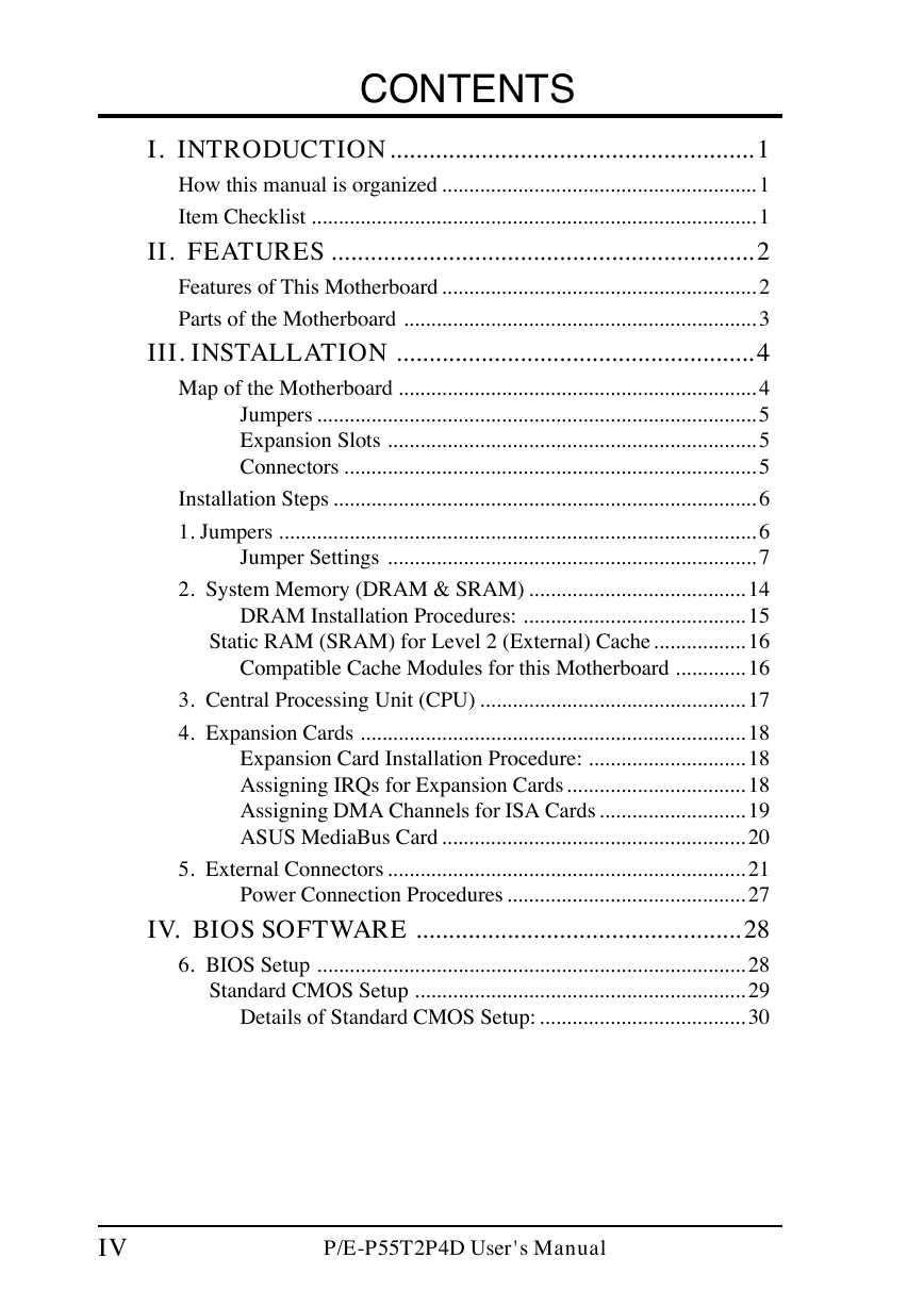
CONTENTS
I. INTRODUCTION........................................................1
How this manual is organized .......................................................... 1
Item Checklist .................................................................................. 1
II. FEATURES .................................................................2
Features of This Motherboard .......................................................... 2
Parts of the Motherboard ................................................................. 3
III. INSTALLATION .......................................................4
Map of the Motherboard .................................................................. 4
Jumpers ................................................................................. 5
Expansion Slots .................................................................... 5
Connectors ............................................................................ 5
Installation Steps .............................................................................. 6
1. Jumpers ........................................................................................ 6
Jumper Settings .................................................................... 7
2. System Memory (DRAM & SRAM) ........................................ 14
DRAM Installation Procedures: ......................................... 15
Static RAM (SRAM) for Level 2 (External) Cache ................. 16
Compatible Cache Modules for this Motherboard ............. 16
3. Central Processing Unit (CPU) ................................................. 17
4. Expansion Cards ....................................................................... 18
Expansion Card Installation Procedure: ............................. 18
Assigning IRQs for Expansion Cards................................. 18
Assigning DMA Channels for ISA Cards ........................... 19
ASUS MediaBus Card ........................................................ 20
5. External Connectors .................................................................. 21
Power Connection Procedures ............................................ 27
IV. BIOS SOFTWARE ..................................................28
6. BIOS Setup ............................................................................... 28
Standard CMOS Setup ............................................................. 29
Details of Standard CMOS Setup: ...................................... 30
IV
P/E-P55T2P4D User's Manual
�
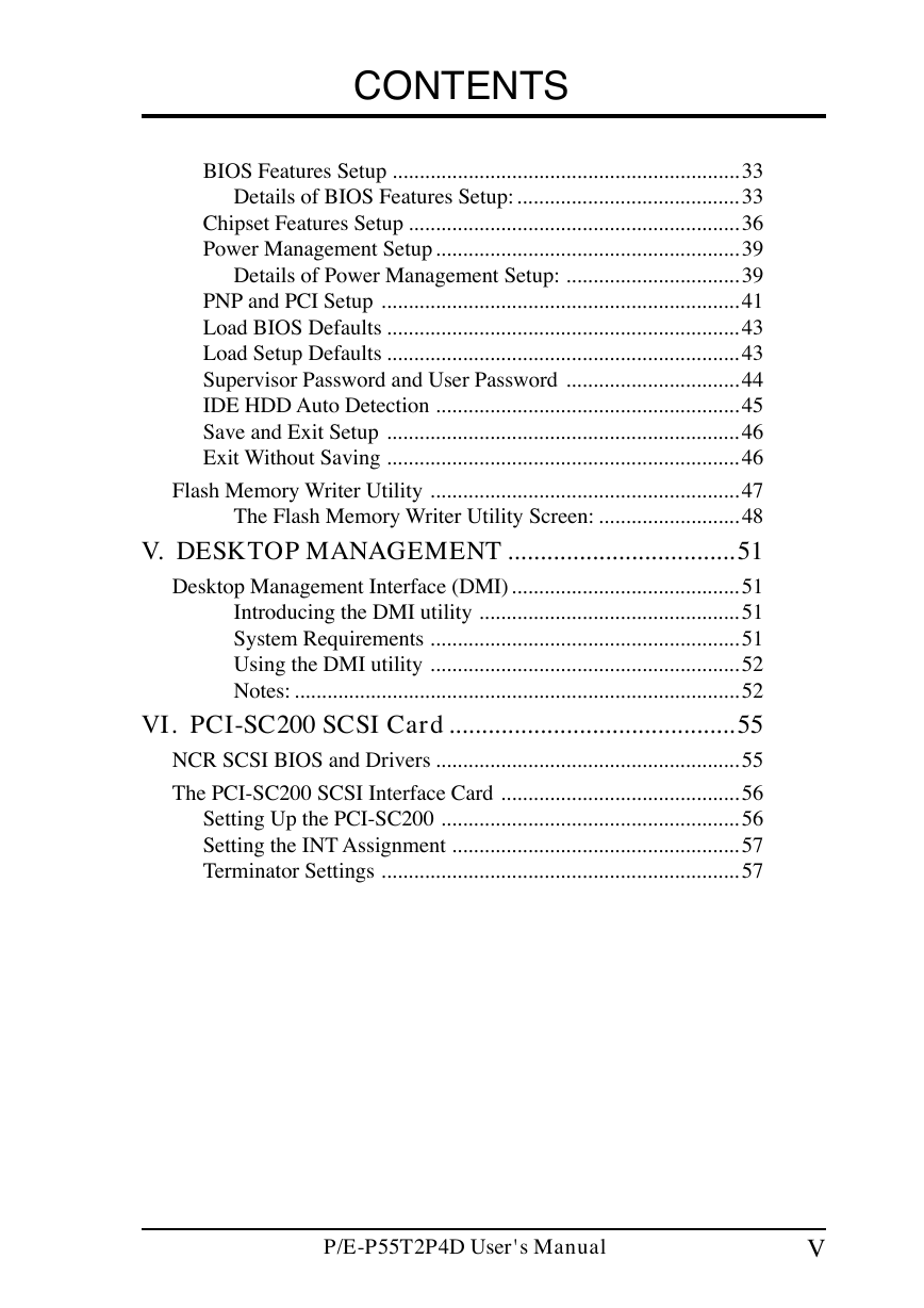
CONTENTS
BIOS Features Setup ................................................................ 33
Details of BIOS Features Setup:......................................... 33
Chipset Features Setup ............................................................. 36
Power Management Setup........................................................ 39
Details of Power Management Setup: ................................ 39
PNP and PCI Setup .................................................................. 41
Load BIOS Defaults ................................................................. 43
Load Setup Defaults ................................................................. 43
Supervisor Password and User Password ................................ 44
IDE HDD Auto Detection ........................................................ 45
Save and Exit Setup ................................................................. 46
Exit Without Saving ................................................................. 46
Flash Memory Writer Utility ......................................................... 47
The Flash Memory Writer Utility Screen: .......................... 48
V. DESKTOP MANAGEMENT ...................................51
Desktop Management Interface (DMI).......................................... 51
Introducing the DMI utility ................................................ 51
System Requirements ......................................................... 51
Using the DMI utility ......................................................... 52
Notes: .................................................................................. 52
VI. PCI-SC200 SCSI Card............................................55
NCR SCSI BIOS and Drivers ........................................................ 55
The PCI-SC200 SCSI Interface Card ............................................ 56
Setting Up the PCI-SC200 ....................................................... 56
Setting the INT Assignment ..................................................... 57
Terminator Settings .................................................................. 57
P/E-P55T2P4D User's Manual
V
�
FCC & DOC COMPLIANCE
Federal Communications Commission Statement
This device complies with FCC Rules Part 15. Operation is subject to the following
two conditions:
• This device may not cause harmful interference, and
• This device must accept any interference received, including interference that
may cause undesired operation.
This equipment has been tested and found to comply with the limits for a Class B
digital device, pursuant to Part 15 of the FCC Rules. These limits are designed to
provide reasonable protection against harmful interference in a residential installa-
tion. This equipment generates, uses and can radiate radio frequency energy and, if
not installed and used in accordance with manufacturer's instructions, may cause
harmful interference to radio communications. However, there is no guarantee that
interference will not occur in a particular installation. If this equipment does cause
harmful interference to radio or television reception, which can be determined by
turning the equipment off and on, the user is encouraged to try to correct the inter-
ference by one or more of the following measures:
• Re-orient or relocate the receiving antenna.
•
• Connect the equipment to an outlet on a circuit different from that to which
Increase the separation between the equipment and receiver.
the receiver is connected.
• Consult the dealer or an experienced radio/TV technician for help.
WARNING: The use of shielded cables for connection of the monitor to the graphics
card is required to assure compliance with FCC regulations. Changes or modifica-
tions to this unit not expressly approved by the party responsible for compliance
could void the user's authority to operate this equipment.
Canadian Department of Communications Statement
This digital apparatus does not exceed the Class B limits for radio noise emissions
from digital apparatus set out in the Radio Interference Regulations of the Cana-
dian Department of Communications.
VI
P/E-P55T2P4D User's Manual
�
)
t
s
i
l
I
N
O
T
C
U
D
O
R
T
N
I
.
I
k
c
e
h
C
/
l
a
u
n
a
M
(
I. INTRODUCTION
How this manual is organized
This manual is divided into the following sections:
Introduction: Manual information and checklist
I.
II. Features: Information and specifications concerning this product
III. Installation: Instructions on setting up the motherboard
IV. BIOS Setup: BIOS software setup information
V. DMI Utility: BIOS supported Desktop Management Interface
VI. PCI-SC200: Installation of an optional SCSI card
Item Checklist
Please check that your package is complete. If you discover damaged or missing
items, please contact your retailer.
The P/E-P55T2P4D motherboard
2 serial port ribbon cables attached to a mounting bracket
1 parallel ribbon cable with mounting bracket
1 IDE ribbon cable
1 floppy ribbon cable
1 diskette containing support software as follows:
• Flash Memory Writer utility to update motherboard BIOS
• Binary file containing a BIOS version
• Desktop Management Interface (DMI) software
• System Configuration Utility (SCU)
• Readme files give instructions on use of the files
1 diskette containing:
• Onboard enhanced IDE driver
1 diskette containing:
• EISA Configuration Utility
This user's manual
ASUS 256/512KB Pipelined Burst Cache Module with TAG RAM
Optional PS/2 mouse cable with mounting bracket
Optional infrared module
Optional PCI-SC200 Fast-SCSI card
P/E-P55T2P4D User’s Manual
1
�
(
F
e
a
t
u
r
e
s
)
I
I
.
F
E
A
T
U
R
E
S
II. FEATURES
Features of This Motherboard
The P/E-P55T2P4D is carefully designed for the demanding corporate PC user who
wants a high performance server motherboard that:
• Easy Installation: Is equipped with BIOS that supports auto
detection of hard drives and Plug and Play to make setup of hard drives and
expansion cards virtually automatic.
• Multi-Processor/Multi-Speed Support: Supports two Pentium CPU (75-
200MHz). (See page 17)
Intel Chipset: Features Intel's 430HX PCIset with EISA I/O subsystems.
•
• Error Checking and Correcting (ECC): Using Intel's 430HX PCIset to-
gether with parity DRAM modules can detect multi-bit memory
errors and correct 1-bit memory errors.
• Desktop Management Interface (DMI): Supports DMI through BIOS which
allows hardware to communicate within a standard protocol
creating a higher level of compatibility (see section V).
• L2 Cache: This motherboard has 0KB cache onboard and uses a Pipelined
Burst Sychronous cache module to upgrade to 256KB or 512KB (See page
16 for compatible cache modules)
• Versatile DRAM Memory Support: Supports eight 72-pin SIMMs of 4MB,
8MB, 16MB, 32MB, or 64MB to form a memory size between 8MB to 512MB.
Supports both Fast Page Mode (FPM) and Extended Data Output (EDO) SIMMs
(see page 14).
• EISA, ISA, and PCI Expansion Slots: Provides four 32-bit EISA slots, one
16-bit ISA slot, three 32-bit PCI slots, and one PCI/MediaBus 2.0 which al-
lows the use of either a standard PCI card or the ASUS MediaBus Card.
•
functions
in one easy-to-install card.
• ASUS MediaBus Rev 2.0: Features an expansion slot extension shared with
PCI Slot 4 for an optional high-performance expansion card which includes
(For revision
two
compatibility information, please refer to page 20.)
Super Multi-I/O: Provides two high-speed UART compatible serial ports
and one parallel port with EPP and ECP capabilities. UART2 can also be
directed from COM2 to the Infrared Module for wireless connections. Two
floppy drives of either 5.25" or 3.5" (1.44MB or 2.88MB) are also supported
without an external card. The Japanese "Floppy 3 mode" (3.5" 1.2MB)
floppy standard is also supported.
• NCR SCSI BIOS: This motherboard has firmware that supports the optional
ASUS PCI-SC200 SCSI controller cards. (see section VI)
2
P/E-P55T2P4D User’s Manual
�





 2023年江西萍乡中考道德与法治真题及答案.doc
 2012年重庆南川中考生物真题及答案.doc
 2013年江西师范大学地理学综合及文艺理论基础考研真题.doc
 2020年四川甘孜小升初语文真题及答案I卷.doc
 2020年注册岩土工程师专业基础考试真题及答案.doc
 2023-2024学年福建省厦门市九年级上学期数学月考试题及答案.doc
 2021-2022学年辽宁省沈阳市大东区九年级上学期语文期末试题及答案.doc
 2022-2023学年北京东城区初三第一学期物理期末试卷及答案.doc
 2018上半年江西教师资格初中地理学科知识与教学能力真题及答案.doc
 2012年河北国家公务员申论考试真题及答案-省级.doc
 2020-2021学年江苏省扬州市江都区邵樊片九年级上学期数学第一次质量检测试题及答案.doc
 2022下半年黑龙江教师资格证中学综合素质真题及答案.doc