WORLDWIDE
ENGINEERING
STANDARDS
General Specification
Electrical Function
GMW3110
General Motors Local Area Network Enhanced Diagnostic Test Mode
Specification
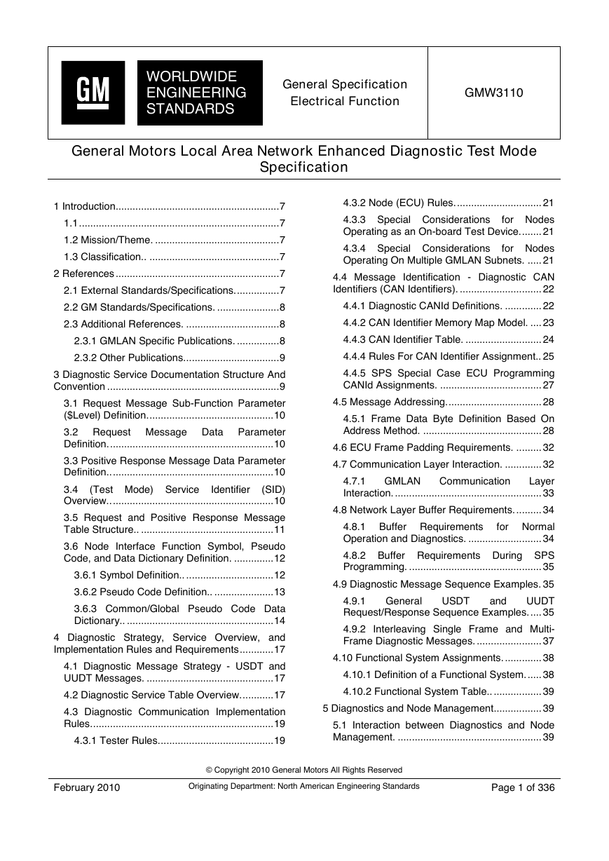
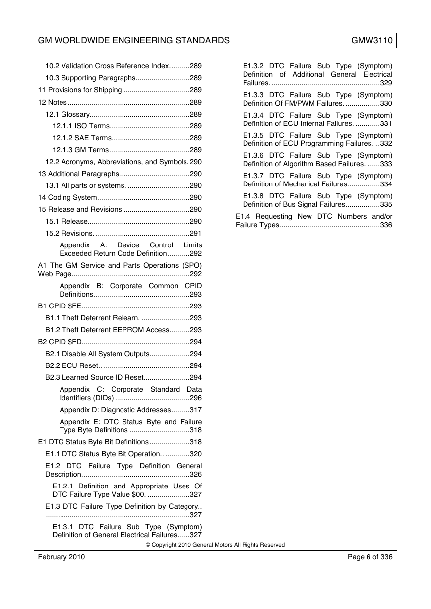
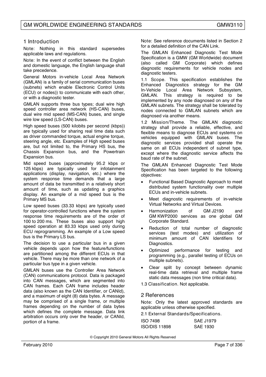
1 Introduction.......................................................... 7
1.1 ....................................................................... 7
1.2 Mission/Theme. ............................................ 7
1.3 Classification.. .............................................. 7
2 References .......................................................... 7
2.1 External Standards/Specifications. ............... 7
4.3.2 Node (ECU) Rules. .............................. 21
4.3.3 Special Considerations
for Nodes
Operating as an On-board Test Device. ....... 21
4.3.4 Special Considerations
for Nodes
Operating On Multiple GMLAN Subnets. ..... 21
4.4 Message Identification - Diagnostic CAN
Identifiers (CAN Identifiers). ............................. 22
2.2 GM Standards/Specifications. ...................... 8
4.4.1 Diagnostic CANId Definitions. ............. 22
2.3 Additional References. ................................. 8
4.4.2 CAN Identifier Memory Map Model. .... 23
2.3.1 GMLAN Specific Publications. ............... 8
4.4.3 CAN Identifier Table. ........................... 24
2.3.2 Other Publications.................................. 9
4.4.4 Rules For CAN Identifier Assignment.. 25
3 Diagnostic Service Documentation Structure And
Convention ............................................................. 9
3.1 Request Message Sub-Function Parameter
($Level) Definition. ............................................ 10
3.2 Request Message Data Parameter
Definition. .......................................................... 10
3.3 Positive Response Message Data Parameter
Definition.. ......................................................... 10
(Test Mode) Service
(SID)
3.4
Overview.. ......................................................... 10
Identifier
3.5 Request and Positive Response Message
Table Structure.. ............................................... 11
3.6 Node Interface Function Symbol, Pseudo
Code, and Data Dictionary Definition. .............. 12
3.6.1 Symbol Definition.. ............................... 12
3.6.2 Pseudo Code Definition.. ..................... 13
3.6.3 Common/Global Pseudo Code Data
Dictionary.. .................................................... 14
4 Diagnostic Strategy, Service Overview, and
Implementation Rules and Requirements ............ 17
4.1 Diagnostic Message Strategy - USDT and
UUDT Messages. ............................................. 17
4.2 Diagnostic Service Table Overview. ........... 17
4.3 Diagnostic Communication Implementation
Rules. ................................................................ 19
4.3.1 Tester Rules. ........................................ 19
4.4.5 SPS Special Case ECU Programming
CANId Assignments. .................................... 27
4.5 Message Addressing. ................................. 28
4.5.1 Frame Data Byte Definition Based On
Address Method. .......................................... 28
4.6 ECU Frame Padding Requirements. ......... 32
4.7 Communication Layer Interaction. ............. 32
4.7.1 GMLAN
Layer
Interaction. .................................................... 33
Communication
4.8 Network Layer Buffer Requirements. ......... 34
4.8.1 Buffer Requirements
for Normal
Operation and Diagnostics. .......................... 34
4.8.2 Buffer Requirements During SPS
Programming. ............................................... 35
4.9 Diagnostic Message Sequence Examples. 35
4.9.1
UUDT
Request/Response Sequence Examples. .... 35
General
USDT
and
4.9.2 Interleaving Single Frame and Multi-
Frame Diagnostic Messages. ....................... 37
4.10 Functional System Assignments. ............. 38
4.10.1 Definition of a Functional System. ..... 38
4.10.2 Functional System Table.. ................. 39
5 Diagnostics and Node Management................. 39
5.1 Interaction between Diagnostics and Node
Management. ................................................... 39
February 2010
© Copyright 2010 General Motors All Rights Reserved
Originating Department: North American Engineering Standards
Page 1 of 336
�
GM WORLDWIDE ENGINEERING STANDARDS
GMW3110
5.2 Communication State Diagram Based On
Version 1.5 of GMW3104. ................................ 40
5.2.1
Initialization
(COMM_INIT) State. ..................................... 41
Communications
5.2.2
Enabled
(COMM_ENABLED) State.. .......................... 41
Communications
7.2.3
ConditionsNotCorrectOrRequestSequenceErr
or ($22, RC_CNCRSE). ................................ 70
7.2.4 RequestOutOfRange ($31, RC_ROOR).
...................................................................... 70
7.2.5 InvalidKey ($35, RC_IK). ..................... 71
Active
5.2.3
(COMM_ACTIVE) State. ............................... 41
Communications
($36,
7.2.6
RC_ENOA). .................................................. 71
ExceedNumberOfAttempts
5.2.4 Enabling Diagnostic Communications. 42
5.2.5 Activation of the Application Triggered
Diagnostic VN.. ............................................. 44
5.2.6 Keeping
the Application Triggered
Diagnostic VN Active. ................................... 45
7.2.7 RequiredTimeDelayNotExpired
($37,
RC_RTDNE).. ............................................... 71
7.2.8
-
ResponsePending ($78, RC_RCR-RP).. ..... 71
RequestCorrectlyReceived
7.2.9 SchedulerFull ($81, RC_SCHDFULL). 71
5.2.7 Deactivation of the Application Triggered
Diagnostic VN.. ............................................. 45
7.2.10 VoltageOutOfRangeFault (High/Low)
($83 RC_VOLTRNG). ................................... 71
5.2.8
VN
Deactivation. ................................................. 46
of Diagnostic
Verification
7.2.11 GeneralProgrammingFailure
($85
RC_PROGFAIL). .......................................... 71
5.2.9 Example: Activation and Deactivation of
the Application Triggered Diagnostic VN. ..... 47
7.2.12
($89
RC_DEV_TYPE_ERR). ................................ 71
DeviceTypeError
6 Wake-up Requirements and Timing Parameters
............................................................................. 48
7.2.13 ReadyForDownload-DTCStored ($99
RC_RFD-DS).. .............................................. 71
6.1 Wake-up Requirements. ............................. 48
6.2 Application Timing Parameters Definitions. 49
6.2.1 Application Timing Parameter P2CE/P2CT
Definition. ...................................................... 49
6.2.2
Parameter
P2CE*/P2CT*Definition. ................................... 54
Application
Timing
6.2.3 Application Timing Parameter Definition
for UUDT Response Messages. ................... 60
6.2.4 Application Timing Parameter P3C
Definition. ...................................................... 61
6.2.5
Parameter
Considerations. ............................................. 62
Application
Timing
6.3 Network Layer Parameter Definitions. ........ 65
6.3.1 Network Layer Timing Parameter
Definitions. .................................................... 65
6.3.2 Tester Network Layer Flow Control
Frame Transmit Parameter Requirements. .. 66
6.3.3 ECU Network Layer Flow Control Frame
Transmit Parameter Requirements. .............. 68
7 Negative Response ($7F) Service Definition .... 69
7.1 Negative Response Message Format. ....... 70
7.2 Return Code Definition. .............................. 70
7.2.1 ServiceNotSupported ($11, RC_SNS). 70
7.2.2 SubFunctionNotSupported-InvalidFormat
($12, RC_SFNS_IF).. .................................... 70
7.2.14 DeviceControlLimitsExceeded
($E3,
RC_DCLE). ................................................... 72
7.3 Negative Response Message Flow Example.
.......................................................................... 72
7.3.1 Tester Requests An Unsupported
Service.. ........................................................ 72
8 Diagnostic Services (Test Modes) Definition .... 72
8.1 ClearDiagnosticInformation ($04) Service. 72
8.1.1 Service Description. ............................. 72
8.1.2 Request Message Definition. .............. 73
8.1.3 Positive Response Message Definition.
...................................................................... 73
8.1.4 Supported Negative Response Codes
(RC_). ........................................................... 73
8.1.5
Example
ClearDiagnosticInformation. ......................... 73
Message
Flow
8.1.6 Node Interface Function. ..................... 74
8.1.7 Node Verification Procedure. .............. 75
8.1.8 Tester implications. .............................. 76
8.2 InitiateDiagnosticOperation ($10) Service. 77
8.2.1 Service Description. ............................. 77
8.2.2 Request Message Definition. .............. 77
8.2.3 Positive Response Message Definition.
...................................................................... 79
February 2010
© Copyright 2010 General Motors All Rights Reserved
Page 2 of 336
�
GM WORLDWIDE ENGINEERING STANDARDS
GMW3110
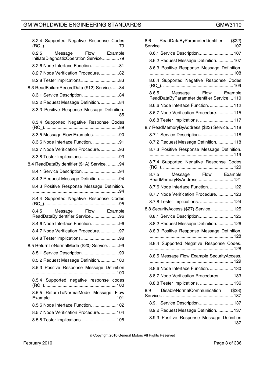
8.2.4 Supported Negative Response Codes
(RC_). ............................................................ 79
ReadDataByParameterIdentifier
8.6
($22)
Service. .......................................................... 107
8.2.5
Example
InitiateDiagnosticOperation Service. ............. 79
Message
Flow
8.2.6 Node Interface Function. ..................... 81
8.2.7 Node Verification Procedure. ............... 82
8.2.8 Tester Implications. .............................. 83
8.3 ReadFailureRecordData ($12) Service. ..... 84
8.3.1 Service Description. ............................. 84
8.3.2 Request Message Definition. ............... 84
8.3.3 Positive Response Message Definition.
...................................................................... 85
8.3.4 Supported Negative Response Codes
(RC_). ............................................................ 89
8.6.1 Service Description.. .......................... 107
8.6.2 Request Message Definition. ............ 107
8.6.3 Positive Response Message Definition.
.................................................................... 108
8.6.4 Supported Negative Response Codes
(RC_). ......................................................... 109
8.6.5
Example
ReadDataByParameterIdentifier Service. .. 110
Message
Flow
8.6.6 Node Interface Function. ................... 112
8.6.7 Node Verification Procedure. ............ 115
8.6.8 Tester Implications. ........................... 117
8.7 ReadMemoryByAddress ($23) Service. ... 118
8.3.5 Message Flow Examples. .................... 90
8.7.1 Service Description. ........................... 118
8.3.6 Node Interface Function. ..................... 91
8.7.2 Request Message Definition. ............ 118
8.3.7 Node Verification Procedure. ............... 93
8.3.8 Tester Implications. .............................. 93
8.4 ReadDataByIdentifier ($1A) Service. ......... 94
8.4.1 Service Description. ............................. 94
8.4.2 Request Message Definition. ............... 94
8.4.3 Positive Response Message Definition.
...................................................................... 94
8.4.4 Supported Negative Response Codes
(RC_)............................................................. 95
8.4.5
Example
ReadDataByIdentifier Service. ...................... 96
Message
Flow
8.7.3 Positive Response Message Definition.
.................................................................... 119
8.7.4 Supported Negative Response Codes
(RC_). ......................................................... 120
8.7.5
Example
ReadMemoryByAddress. ............................ 121
Message
Flow
8.7.6 Node Interface Function. ................... 122
8.7.7 Node Verification Procedure. ............ 123
8.7.8 Tester Implications. ........................... 124
8.8 SecurityAccess ($27) Service. ................. 125
8.8.1 Service Description.. .......................... 125
8.4.6 Node Interface Function. ..................... 96
8.8.2 Request Message Definition. ............ 126
8.4.7 Node Verification Procedure. ............... 97
8.4.8 Tester Implications. .............................. 98
8.5 ReturnToNormalMode ($20) Service. ........ 99
8.5.1 Service Description. ............................. 99
8.5.2 Request Message Definition. ............. 100
8.5.3 Positive Response Message Definition
.................................................................... 100
8.5.4 Supported negative response codes
(RC_). .......................................................... 100
8.5.5 ReturnToNormalMode Message Flow
Example. ..................................................... 101
8.5.6 Node Interface Function. ................... 102
8.5.7 Node Verification Procedure. ............. 104
8.5.8 Tester Implications. ............................ 105
8.8.3 Positive Response Message Definition.
.................................................................... 128
8.8.4 Supported Negative Response Codes.
.................................................................... 128
8.8.5 Message Flow Example SecurityAccess.
.................................................................... 129
8.8.6 Node Interface Function. ................... 130
8.8.7 Node Verification Procedures. ........... 133
8.8.8 Tester Implications. ........................... 136
8.9
($28)
Service.. ......................................................... 137
DisableNormalCommunication
8.9.1 Service Description. ........................... 137
8.9.2 Request Message Definition. ............ 137
8.9.3 Positive Response Message Definition
.................................................................... 137
February 2010
© Copyright 2010 General Motors All Rights Reserved
Page 3 of 336
�
GM WORLDWIDE ENGINEERING STANDARDS
GMW3110
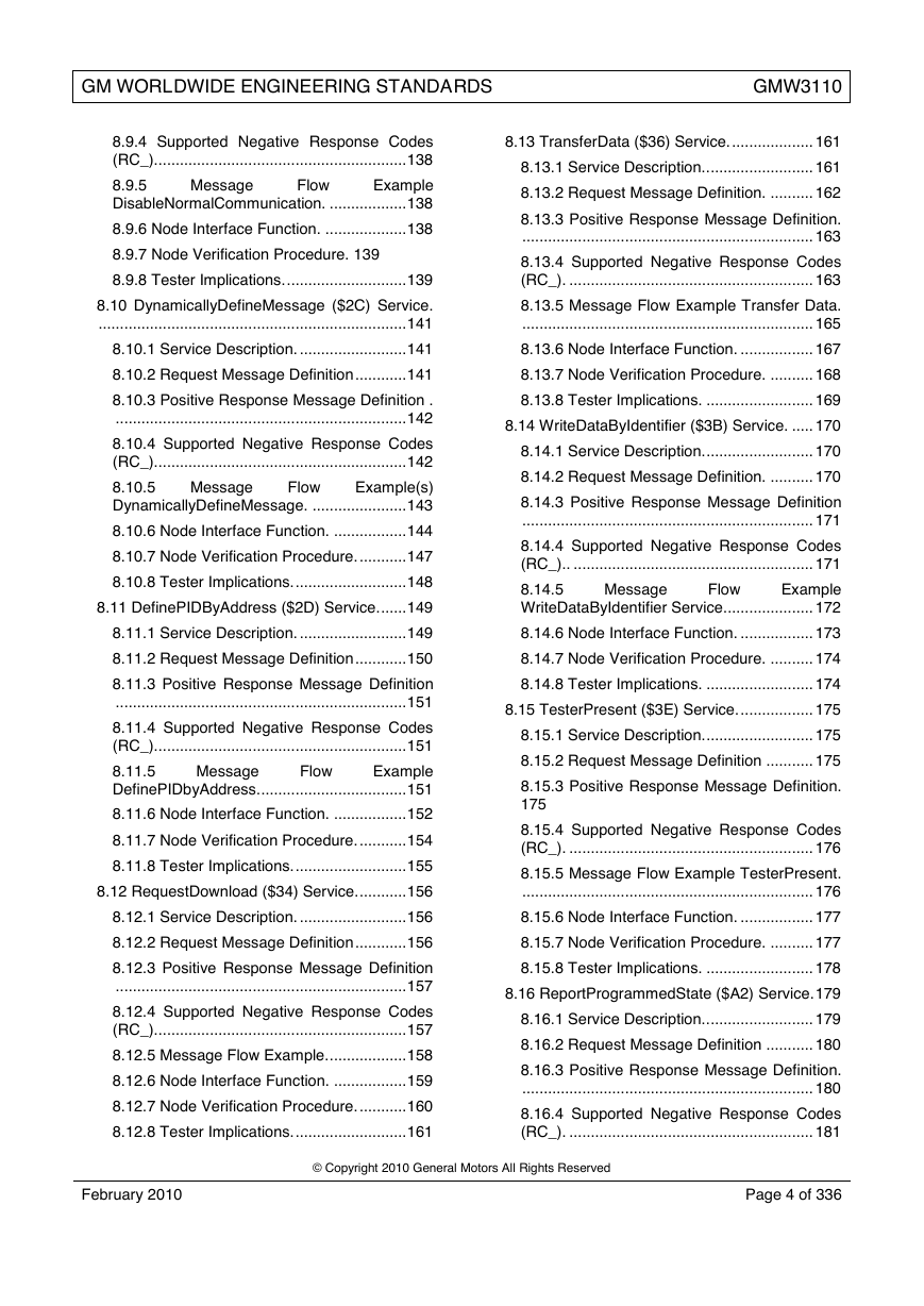
8.9.4 Supported Negative Response Codes
(RC_). .......................................................... 138
8.9.5
Example
DisableNormalCommunication. .................. 138
Message
Flow
8.9.6 Node Interface Function. ................... 138
8.9.7 Node Verification Procedure. 139
8.9.8 Tester Implications. ............................ 139
8.13 TransferData ($36) Service. ................... 161
8.13.1 Service Description.. ........................ 161
8.13.2 Request Message Definition. .......... 162
8.13.3 Positive Response Message Definition.
.................................................................... 163
8.13.4 Supported Negative Response Codes
(RC_). ......................................................... 163
8.10 DynamicallyDefineMessage ($2C) Service.
........................................................................ 141
8.13.5 Message Flow Example Transfer Data.
.................................................................... 165
8.10.1 Service Description. ......................... 141
8.13.6 Node Interface Function. ................. 167
8.10.2 Request Message Definition ............ 141
8.13.7 Node Verification Procedure. .......... 168
8.10.3 Positive Response Message Definition .
.................................................................... 142
8.10.4 Supported Negative Response Codes
(RC_). .......................................................... 142
8.10.5
Example(s)
DynamicallyDefineMessage. ...................... 143
Message
Flow
8.10.6 Node Interface Function. ................. 144
8.10.7 Node Verification Procedure. ........... 147
8.10.8 Tester Implications. .......................... 148
8.11 DefinePIDByAddress ($2D) Service. ...... 149
8.13.8 Tester Implications. ......................... 169
8.14 WriteDataByIdentifier ($3B) Service. ..... 170
8.14.1 Service Description. ......................... 170
8.14.2 Request Message Definition. .......... 170
8.14.3 Positive Response Message Definition
.................................................................... 171
8.14.4 Supported Negative Response Codes
(RC_).. ........................................................ 171
Example
8.14.5
WriteDataByIdentifier Service. .................... 172
Message
Flow
8.11.1 Service Description. ......................... 149
8.14.6 Node Interface Function. ................. 173
8.11.2 Request Message Definition ............ 150
8.14.7 Node Verification Procedure. .......... 174
8.11.3 Positive Response Message Definition
.................................................................... 151
8.11.4 Supported Negative Response Codes
(RC_). .......................................................... 151
8.11.5
Example
DefinePIDbyAddress. .................................. 151
Message
Flow
8.11.6 Node Interface Function. ................. 152
8.11.7 Node Verification Procedure. ........... 154
8.11.8 Tester Implications. .......................... 155
8.12 RequestDownload ($34) Service. ........... 156
8.14.8 Tester Implications. ......................... 174
8.15 TesterPresent ($3E) Service. ................. 175
8.15.1 Service Description. ......................... 175
8.15.2 Request Message Definition ........... 175
8.15.3 Positive Response Message Definition.
175
8.15.4 Supported Negative Response Codes
(RC_). ......................................................... 176
8.15.5 Message Flow Example TesterPresent.
.................................................................... 176
8.12.1 Service Description. ......................... 156
8.15.6 Node Interface Function. ................. 177
8.12.2 Request Message Definition ............ 156
8.15.7 Node Verification Procedure. .......... 177
8.12.3 Positive Response Message Definition
.................................................................... 157
8.12.4 Supported Negative Response Codes
(RC_). .......................................................... 157
8.12.5 Message Flow Example. .................. 158
8.12.6 Node Interface Function. ................. 159
8.12.7 Node Verification Procedure. ........... 160
8.12.8 Tester Implications. .......................... 161
8.15.8 Tester Implications. ......................... 178
8.16 ReportProgrammedState ($A2) Service. 179
8.16.1 Service Description.. ........................ 179
8.16.2 Request Message Definition ........... 180
8.16.3 Positive Response Message Definition.
.................................................................... 180
8.16.4 Supported Negative Response Codes
(RC_). ......................................................... 181
February 2010
© Copyright 2010 General Motors All Rights Reserved
Page 4 of 336
�
GM WORLDWIDE ENGINEERING STANDARDS
GMW3110
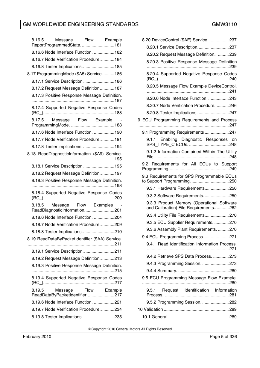
8.16.5
Example
ReportProgrammedState. ........................... 181
Message
Flow
8.16.6 Node Interface Function. ................. 182
8.16.7 Node Verification Procedure. ........... 184
8.16.8 Tester Implications. .......................... 185
8.17 ProgrammingMode ($A5) Service. ......... 186
8.17.1 Service Description. ......................... 186
8.17.2 Request Message Definition ............ 187
8.17.3 Positive Response Message Definition.
.................................................................... 187
8.17.4 Supported Negative Response Codes
(RC_). .......................................................... 188
-
8.17.5 Message
ProgrammingMode. .................................... 188
Example
Flow
8.20 DeviceControl ($AE) Service. ................ 237
8.20.1 Service Description. ......................... 237
8.20.2 Request Message Definition. ......... 239
8.20.3 Positive Response Message Definition
.................................................................... 239
8.20.4 Supported Negative Response Codes
(RC_). ......................................................... 240
8.20.5 Message Flow Example DeviceControl.
.................................................................... 241
8.20.6 Node Interface Function. ................. 243
8.20.7 Node Verification Procedure. .......... 246
8.20.8 Tester Implications. ......................... 247
9 ECU Programming Requirements and Process
........................................................................... 247
8.17.6 Node Interface Function. ................. 190
9.1 Programming Requirements .................... 247
8.17.7 Node Verification Procedure. ........... 191
8.17.8 Tester implications. .......................... 194
8.18 ReadDiagnosticInformation ($A9) Service.
........................................................................ 195
8.18.1 Service Description. ......................... 195
8.18.2 Request Message Definition. ........... 197
8.18.3 Positive Response Message Definition.
.................................................................... 198
8.18.4 Supported Negative Response Codes
(RC_). .......................................................... 200
8.18.5 Message
-
ReadDiagnosticInformation......................... 201
Examples
Flow
8.18.6 Node Interface Function. ................. 204
8.18.7 Node Verification Procedure. ........... 209
8.18.8 Tester Implications. .......................... 210
8.19 ReadDataByPacketIdentifier ($AA) Service.
........................................................................ 211
8.19.1 Service Description.. ........................ 211
8.19.2 Request Message Definition. ........... 213
8.19.3 Positive Response Message Definition.
.................................................................... 215
9.1.1 Enabling Diagnostic Responses on
SPS_TYPE_C ECUs. ................................. 248
9.1.2 Information Contained Within The Utility
File. ............................................................. 248
9.2 Requirements for All ECUs to Support
Programming. ................................................. 249
9.3 Requirements for SPS Programmable ECUs
to Support Programming. ............................... 250
9.3.1 Hardware Requirements.................... 250
9.3.2 Software Requirements. .................... 250
9.3.3 Product Memory (Operational Software
and Calibration) File Requirements.. .......... 262
9.3.4 Utility File Requirements. ................... 270
9.3.5 ECU Supplier Requirements. ............ 270
9.3.6 Assembly Plant Requirements. ......... 270
9.4 ECU Programming Process. .................... 271
9.4.1 Read Identification Information Process.
.................................................................... 271
9.4.2 Retrieve SPS Data Process. ............. 273
9.4.3 Programming Session. ...................... 273
9.4.4 Summary. .......................................... 280
8.19.4 Supported Negative Response Codes
(RC_). .......................................................... 217
9.5 ECU Programming Message Flow Example.
........................................................................ 280
8.19.5
Example
ReadDataByPacketIdentifier. ...................... 217
Message
Flow
9.5.1 Request
Information
Process.. ..................................................... 281
Identification
8.19.6 Node Interface Function. ................. 221
9.5.2 Programming Session. ...................... 282
8.19.7 Node Verification Procedure. ........... 234
10 Validation ...................................................... 289
8.19.8 Tester Implications. .......................... 235
10.1 General. .................................................. 289
February 2010
© Copyright 2010 General Motors All Rights Reserved
Page 5 of 336
�
GM WORLDWIDE ENGINEERING STANDARDS
GMW3110
E1.3.2 DTC Failure Sub Type (Symptom)
Definition of Additional General Electrical
Failures. ...................................................... 329
E1.3.3 DTC Failure Sub Type (Symptom)
Definition Of FM/PWM Failures. ................. 330
E1.3.4 DTC Failure Sub Type (Symptom)
Definition of ECU Internal Failures. ............ 331
E1.3.5 DTC Failure Sub Type (Symptom)
Definition of ECU Programming Failures. .. 332
E1.3.6 DTC Failure Sub Type (Symptom)
Definition of Algorithm Based Failures. ...... 333
E1.3.7 DTC Failure Sub Type (Symptom)
Definition of Mechanical Failures................ 334
E1.3.8 DTC Failure Sub Type (Symptom)
Definition of Bus Signal Failures................. 335
E1.4 Requesting New DTC Numbers and/or
Failure Types. ................................................. 336
10.2 Validation Cross Reference Index. ......... 289
10.3 Supporting Paragraphs........................... 289
11 Provisions for Shipping ................................. 289
12 Notes ............................................................. 289
12.1 Glossary.................................................. 289
12.1.1 ISO Terms ........................................ 289
12.1.2 SAE Terms ....................................... 289
12.1.3 GM Terms ........................................ 289
12.2 Acronyms, Abbreviations, and Symbols. 290
13 Additional Paragraphs ................................... 290
13.1 All parts or systems. ............................... 290
14 Coding System .............................................. 290
15 Release and Revisions ................................. 290
15.1 Release................................................... 290
15.2 Revisions. ............................................... 291
Appendix A: Device Control
Limits
Exceeded Return Code Definition ........... 292
A1 The GM Service and Parts Operations (SPO)
Web Page. .......................................................... 292
Appendix B: Corporate Common CPID
Definitions ................................................ 293
B1 CPID $FE ...................................................... 293
B1.1 Theft Deterrent Relearn. ........................ 293
B1.2 Theft Deterrent EEPROM Access. ......... 293
B2 CPID $FD...................................................... 294
B2.1 Disable All System Outputs.................... 294
B2.2 ECU Reset.. ........................................... 294
B2.3 Learned Source ID Reset....................... 294
Appendix C: Corporate Standard Data
Identifiers (DIDs) ..................................... 296
Appendix D: Diagnostic Addresses ......... 317
Appendix E: DTC Status Byte and Failure
Type Byte Definitions .............................. 318
E1 DTC Status Byte Bit Definitions .................... 318
E1.1 DTC Status Byte Bit Operation.. ............ 320
E1.2 DTC Failure Type Definition General
Description. ..................................................... 326
E1.2.1 Definition and Appropriate Uses Of
DTC Failure Type Value $00. ..................... 327
E1.3 DTC Failure Type Definition by Category..
........................................................................ 327
E1.3.1 DTC Failure Sub Type (Symptom)
Definition of General Electrical Failures. ..... 327
February 2010
© Copyright 2010 General Motors All Rights Reserved
Page 6 of 336
�
GM WORLDWIDE ENGINEERING STANDARDS
GMW3110
1 Introduction
Note: Nothing
applicable laws and regulations.
in
this standard supersedes
Note: In the event of conflict between the English
and domestic language, the English language shall
take precedence.
General Motors in-vehicle Local Area Network
(GMLAN) is a family of serial communication buses
(subnets) which enable Electronic Control Units
(ECU) or nodes)) to communicate with each other,
or with a diagnostic tester.
GMLAN supports three bus types; dual wire high
speed controller area network (HS-CAN) buses,
dual wire mid speed (MS-CAN) buses, and single
wire low speed (LS-CAN) buses.
High speed buses (500 kilobits per second (kbps))
are typically used for sharing real time data such
as driver commanded torque, actual engine torque,
steering angle, etc. Examples of High speed buses
are, but not limited to, the Primary HS bus, the
Chassis Expansion bus, and
the Powertrain
Expansion bus.
for
typically used
Mid speed buses (approximately 95.2 kbps or
125 kbps) are
infotainment
applications (display, navigation, etc.) where the
system response time demands that a large
amount of data be transmitted in a relatively short
amount of time, such as updating a graphics
display. An example of a mid speed bus is the
Primary MS bus.
Low speed buses (33.33 kbps) are typically used
for operator-controlled functions where the system
response time requirements are of the order of
100 to 200 ms. These buses also support high
speed operation at 83.33 kbps used only during
ECU reprogramming. An example of a Low speed
bus is the Primary LS bus.
The decision to use a particular bus in a given
vehicle depends upon how the feature/functions
are partitioned among the different ECUs in that
vehicle. There may be more than one network of a
particular bus type in a given vehicle.
GMLAN buses use the Controller Area Network
(CAN) communications protocol. Data is packaged
into CAN messages, which are segmented into
CAN frames. Each CAN frame includes header
data (also known as the CAN Identifier, or CANId),
and a maximum of eight (8) data bytes. A message
may be comprised of a single frame, or multiple
frames depending on the number of data bytes
which defines the complete message. Data link
arbitration occurs only over the header, or CANId,
portion of a frame.
Note: See reference documents listed in Section 2
for a detailed definition of the CAN Link.
The GMLAN Enhanced Diagnostic Test Mode
Specification is a GMW (GM Worldwide) document
(also called GM Corporate) which defines
diagnostic requirements for vehicle nodes and
diagnostic testers.
for
the
1.1 Scope. This specification establishes
Enhanced Diagnostics strategy
the GM
In-Vehicle Local Area Network Subsystem,
GMLAN. This strategy
to be
implemented by any node diagnosed on any of the
GMLAN subnets. The strategy shall be tolerated by
nodes connected to GMLAN subnets which are
diagnosed via another means.
required
is
1.2 Mission/Theme. The GMLAN diagnostic
strategy shall provide a reliable, effective, and
flexible means to diagnose ECUs and systems on
vehicles equipped with GMLAN buses. The
diagnostic services provided shall operate the
same on all ECUs independent of subnet type,
except where the diagnostic service affects the
baud rate of the subnet.
The GMLAN Enhanced Diagnostic Test Mode
Specification has been targeted to the following
objectives:
Functional Based Diagnostic Approach to meet
distributed system functionality over multiple
ECUs and in-vehicle subnets.
Meet diagnostic requirements of in-vehicle
Virtual Networks and Virtual Devices.
Harmonization
and
GM KWP2000 services as one global GM
Corporate Standard.
GM J2190
of
Reduction of
total number of diagnostic
(test modes) and utilization of
for
services
minimum amount of CAN
Diagnostics.
Identifiers
Optimized performance
testing and
programming (e.g., parallel testing of ECUs on
multiple subnets).
for
Clear split by concept between dynamic
real-time data retrieval and multiple frame
static data messages (non time critical data).
1.3 Classification. Not applicable.
2 References
Note: Only the latest approved standards are
applicable unless otherwise specified.
2.1 External Standards/Specifications.
ISO 7498
ISO/DIS 11898
SAE J1979
SAE 1930
February 2010
© Copyright 2010 General Motors All Rights Reserved
Page 7 of 336
�
GM WORLDWIDE ENGINEERING STANDARDS
GMW3110
ISO 15031-5
ISO 15765-2
ISO 15765-4
ISO/TR 8509
SAE J2012
SAE J2178
SAE J2186
2.2 GM Standards/Specifications.
GM1737
GM J1962
GM J2190
GMW3089
GMW3104
GMW3107
GMW3122
GMW4710
GMW15862
TL.07.0054.Rxx
Note: Rxx in the specification number indicates the
revision level of this document.
GM Bill Of Process - General Assembly
Programming and Test.
GM Body Chassis Network Communication
Code
Diagnostic
Common
Specification.
Trouble
Service
Programming
System
(SPS)
Interpreter Programmers Reference Manual.
Vehicle Theft Deterrent Subsystem Technical
Specification (SSTS).
2.3 Additional References.
2.3.1 GMLAN Specific Publications. There are
two
types of GMLAN publications: General
Specifications and Device Specifications.
2.3.1.1 General Specification. The General
Specifications establish the fundamental concepts
needed by a GMLAN ECU (e.g., Communication
Strategies,
Layer
requirements, etc.) For a given ECU, it is possible
that not everything in the General Specifications
will apply. See Figure 1.
Bus Wiring,
Physical
February 2010
© Copyright 2010 General Motors All Rights Reserved
Page 8 of 336
�



 2023年江西萍乡中考道德与法治真题及答案.doc
 2012年重庆南川中考生物真题及答案.doc
 2013年江西师范大学地理学综合及文艺理论基础考研真题.doc
 2020年四川甘孜小升初语文真题及答案I卷.doc
 2020年注册岩土工程师专业基础考试真题及答案.doc
 2023-2024学年福建省厦门市九年级上学期数学月考试题及答案.doc
 2021-2022学年辽宁省沈阳市大东区九年级上学期语文期末试题及答案.doc
 2022-2023学年北京东城区初三第一学期物理期末试卷及答案.doc
 2018上半年江西教师资格初中地理学科知识与教学能力真题及答案.doc
 2012年河北国家公务员申论考试真题及答案-省级.doc
 2020-2021学年江苏省扬州市江都区邵樊片九年级上学期数学第一次质量检测试题及答案.doc
 2022下半年黑龙江教师资格证中学综合素质真题及答案.doc