Previous issues
Changes
Contents
1 Scope
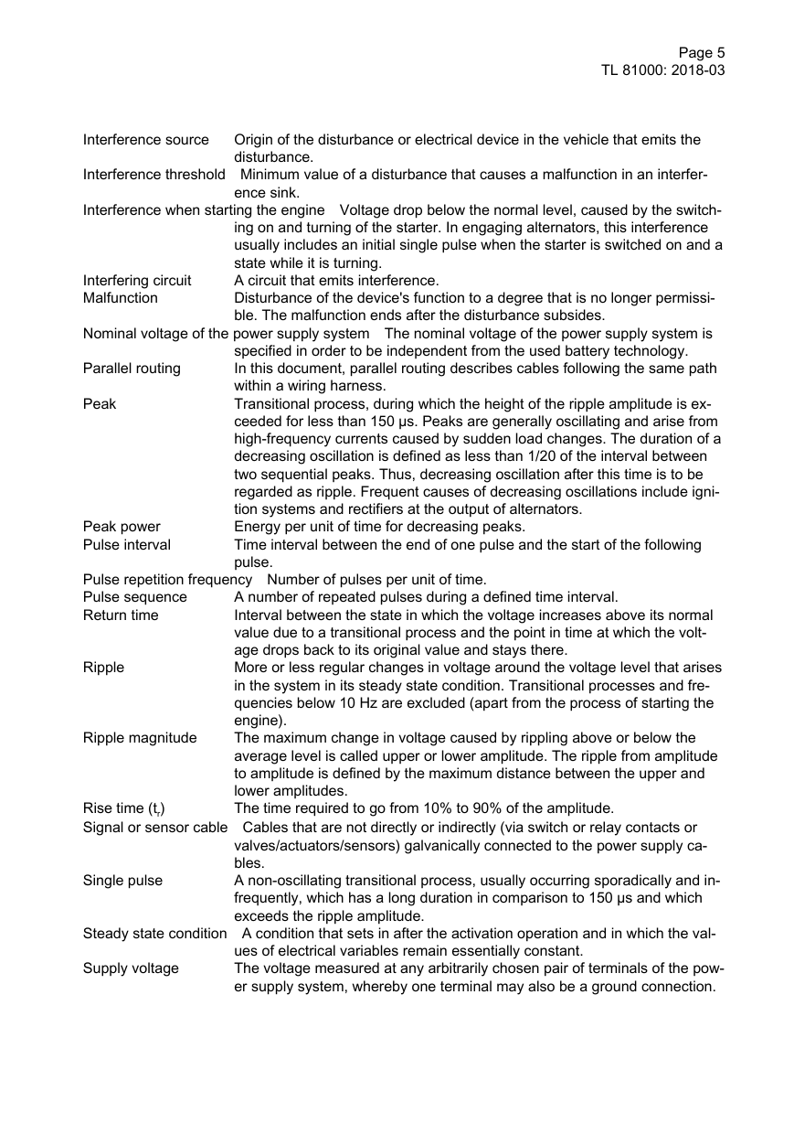
2 Definitions
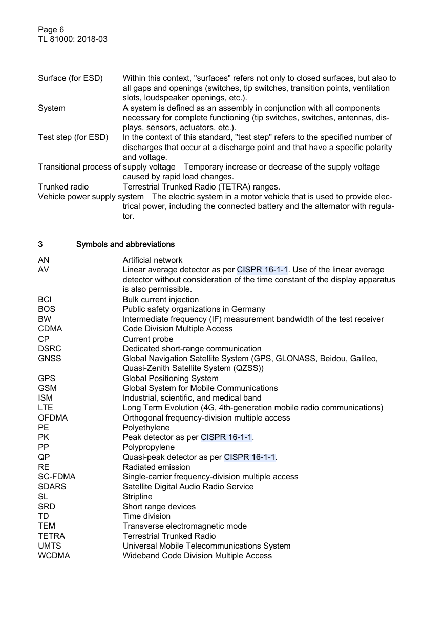
3 Symbols and abbreviations
4 General information
4.1 Requirements and terms
4.1.1 Temperature
4.1.2 Run-in time
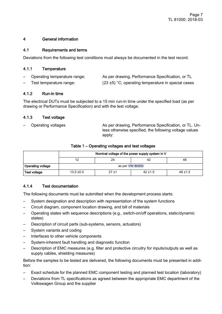
4.1.3 Test voltage
4.1.4 Test documentation
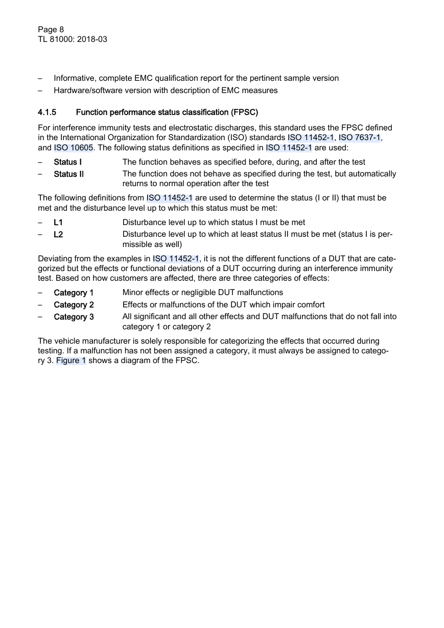
4.1.5 Function performance status classification (FPSC)
5 Component level
5.1 Electrostatic discharge (ESD)
5.1.1 General requirements for ESD component testing
5.1.1.1 Protection targets
5.1.1.2 Test scope and test severity
5.1.1.3 Test equipment and general test requirements
5.1.2 Tests at assembly level (packaging and handling)
5.1.2.1 Test setup and test conditions
5.1.2.2 Procedure
5.1.3 Tests at system level
5.1.3.1 Test setup and test conditions for tests at system level
5.1.3.2 Procedure for the direct discharge test at system level
5.1.3.3 Procedure for the indirect discharge test at system level
5.1.4 ESD documentation/test documents
5.2 Interference immunity
5.2.1 General requirements for component interference immunity tests
5.2.2 BCI test
5.2.3 Antenna
5.2.4 Stripline
5.2.5 Mobile radio communications test
5.2.6 Magnetic field test
5.2.6.1 General information
5.2.6.2 Magnetic field test requirements
5.3 Interference emission
5.3.1 Overview of emission tests and frequency ranges
5.3.2 Specific interference emission terms, definitions, and abbreviations
5.3.2.1 Short-term interference sources – permanent interference sources
5.3.3 General requirements – HF emissions from component measurements
5.3.3.1 Description of the operating states
5.3.3.2 Standard test conditions
5.3.4 Limit classes
5.3.5 Artificial network (AN test)
5.3.5.1 Test setup
5.3.5.2 Test conditions
5.3.5.3 Requirements
5.3.6 Antennas (RE test)
5.3.6.1 Test setup
5.3.6.2 Test conditions
5.3.6.3 Requirements
5.3.7 Stripline (SL test, optional)
5.3.7.1 Test setup
5.3.7.2 Test conditions
5.3.7.3 Requirements
5.3.8 Clamp-on current probe (CP test, optional)
5.3.8.1 Test setup
5.3.8.2 Test conditions
5.3.8.3 Requirements
5.3.9 Magnetic field coil 12 cm
5.3.9.1 Test setup
5.3.9.2 Test conditions
5.3.9.3 Requirements
5.3.10 Magnetic field coil 60 cm
5.3.10.1 Test setup
5.3.10.2 Test conditions
5.3.10.3 Requirements
5.3.11 Isotropic magnetic field coil 100 cm2
5.3.11.1 Test setup
5.3.11.2 Test conditions
5.3.11.3 Requirements
5.4 Pulse
5.4.1 Test equipment
5.4.1.1 Measuring instrument for voltages
5.4.1.2 Artificial network for 12 V/24 V/42 V/48 V vehicle power supplysystems
5.4.1.3 High-current circuit breaker
5.4.1.3.1 Electronic switch
5.4.1.3.2 Mechanical switch
5.4.1.4 Pulse generator
5.4.1.5 Starter battery/power supply
5.4.1.6 Coupling clamp
5.4.1.7 Ground plane
5.4.1.8 Current injection probe
5.4.2 Pulse forms
5.4.2.1 Test pulse 1
5.4.2.2 Test pulse 2
5.4.2.3 Test pulses 3a and 3b
5.4.2.4 Test pulse 5b
5.4.2.5 Test pulse 6
5.4.3 Functional states
5.4.4 Pulsed interference on supply cables
5.4.4.1 Interference immunity verification test
5.4.4.1.1 Measurement setup
5.4.4.1.2 Test sequence
5.4.4.1.3 Set values
5.4.4.1.4 Notes on interference immunity test
5.4.4.2 Interference emission measurement
5.4.4.2.1 Measurement setup
5.4.4.2.2 Interference emission limits for vehicle power supply systems
5.4.5 Pulsed interference on sensor cables
5.4.5.1 Capacitive coupling clamp
5.4.5.1.1 Setting the test voltage
5.4.5.1.2 Test setup for capacitive coupling clamp
5.4.5.2 Current injection probe (BCI probe)
5.4.5.2.1 Setting the test voltage
5.4.5.2.2 Test setup for current injection probe
5.4.5.3 Basic requirements for input circuitry
5.4.5.4 Interference immunity verification test
5.4.5.4.1 Test and set values
6 Vehicle level
6.1 Interference emission
6.1.1 Frequency range during vehicle measurement
6.1.2 Requirements
6.1.3 Measurement setup
6.1.4 Antennas and related components
6.1.5 Test receiver settings and limits for vehicle measurements
6.2 Interference immunity
6.2.1 Interference immunity test (far field)
6.2.2 Mobile radio communications test with exterior antenna attachedto the vehicle
6.2.3 Mobile radio communications test using portable mobile radiocommunications devices in the vehicle interior
6.2.4 Additional measurements in the free field
6.3 Electrostatic discharge – ESD
6.3.1 General requirements for ESD full vehicle testing
6.3.1.1 Protection targets
6.3.1.2 Test scope and test severity
6.3.1.3 Test equipment and general test requirements
6.3.2 Test setup and test conditions for tests at vehicle level
6.3.3 Procedure for tests at vehicle level
7 Applicable documents
8 Bibliography
Appendix A ESD
A.1 Geometric setup of the ESD coupling structure for indirectdischarges at system level
Appendix B Interference immunity
B.1 Test severity levels for BCI testing
B.2 Conversion of dB(µA) into mA
B.3 Magnetic field – correlation between magnetic field strengthH and magnetic flux density B
Appendix C Emission
C.1 Measurements in the AM range
C.2 Subjective evaluation of interference suppression
C.2.1 Analog radio and TV ranges and radio applications
C.2.2 Digital radio and TV ranges (DAB, DVB-T, etc.)
C.2.3 Long-distance interference suppression


 2023年江西萍乡中考道德与法治真题及答案.doc
 2012年重庆南川中考生物真题及答案.doc
 2013年江西师范大学地理学综合及文艺理论基础考研真题.doc
 2020年四川甘孜小升初语文真题及答案I卷.doc
 2020年注册岩土工程师专业基础考试真题及答案.doc
 2023-2024学年福建省厦门市九年级上学期数学月考试题及答案.doc
 2021-2022学年辽宁省沈阳市大东区九年级上学期语文期末试题及答案.doc
 2022-2023学年北京东城区初三第一学期物理期末试卷及答案.doc
 2018上半年江西教师资格初中地理学科知识与教学能力真题及答案.doc
 2012年河北国家公务员申论考试真题及答案-省级.doc
 2020-2021学年江苏省扬州市江都区邵樊片九年级上学期数学第一次质量检测试题及答案.doc
 2022下半年黑龙江教师资格证中学综合素质真题及答案.doc