logo资料库

USB EHCI Spec.pdf

第1页 / 共155页
第2页 / 共155页
第3页 / 共155页
第4页 / 共155页
第5页 / 共155页
第6页 / 共155页
第7页 / 共155页
第8页 / 共155页
资料共155页,剩余部分请下载后查看
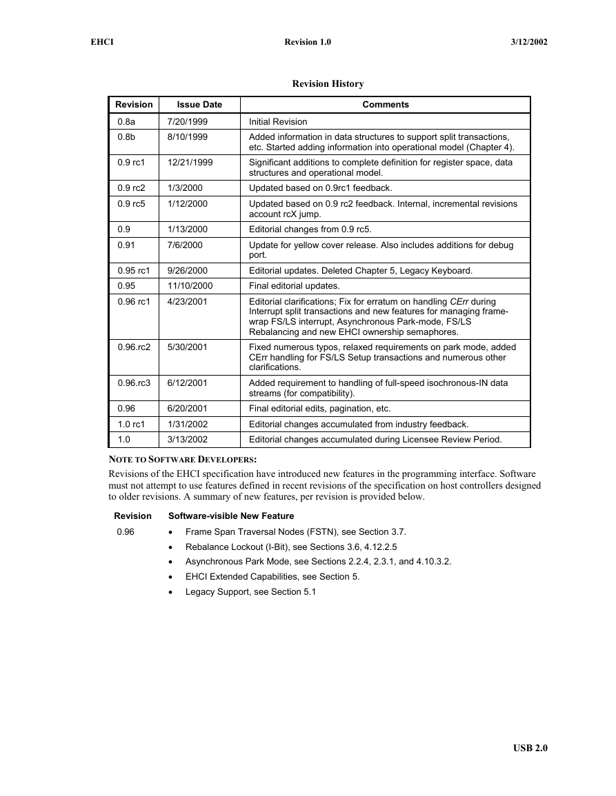
Revision History
1. Introduction
1.1 EHCI Product Compliance
1.2 Architectural Overview
Figure 1-1. Universal Serial Bus, Revision 2.0 System Block Diagram
Figure 1-2. USB 2.0 Host Controller
1.2.1 Interface Architecture
Figure 1-3. General Architecture of Enhanced Host Controller Interface
1.2.2 EHCI Schedule Data Structures
1.2.3 Root Hub Emulation
2. Register Interface
Table 2-1. Enhanced Interface Register Sets
2.1 PCI Configuration Registers (USB)
Table 2-2. PCI Configuration Space Registers
2.1.1 PWRMGT  PCI Power Management Interface
2.1.2 CLASSC  CLASS CODE REGISTER
2.1.3 USBBASE  Register Space Base Address Register
2.1.4 SBRN  Serial Bus Release Number Register
2.1.5 Frame Length Adjustment Register (FLADJ)
2.1.6 Port Wake Capability Register (PORTWAKECAP)
2.1.7 USBLEGSUP  USB Legacy Support Extended Capability
Table 2–3. USBLEGSUP  USB Legacy Support Extended Capability
2.1.8 USBLEGCTLSTS  USB Legacy Support Control/Status
Table 2–4. USBLEGCTLSTS  USB Legacy Support Control/Status
2.2 Host Controller Capability Registers
Table 2-5. Enhanced Host Controller Capability Registers
2.2.1 CAPLENGTH  Capability Registers Length
2.2.2 HCIVERSION  Host Controller Interface Version Number
2.2.3 HCSPARAMS  Structural Parameters
Table 2-6.HCSPARAMS  Host Controller Structural Parameters
2.2.4 HCCPARAMS  Capability Parameters
Table 2-7. HCCPARAMSHost Controller Capability Parameters
2.2.5 HCSP-PORTROUTE  Companion Port Route Description
2.3 Host Controller Operational Registers
Table 2-8. Host Controller Operational Registers
2.3.1 USBCMD  USB Command Register
Table 2-9. USBCMD – USB Command Register Bit Definitions
2.3.2 USBSTS  USB Status Register
Table 2-10. USBSTS USB Status Register Bit Definitions
2.3.3 USBINTR  USB Interrupt Enable Register
Table 2-11. USBINTR - USB Interrupt Enable Register
2.3.4 FRINDEX  Frame Index Register
Table 2-12. FRINDEX  Frame Index Register
2.3.5 CTRLDSSEGMENT  Control Data Structure Segment Register
2.3.6 PERIODICLISTBASE  Periodic Frame List Base Address Register
Table 2-13. PERIODICLISTBASE  Periodic Frame List Base Address Register
2.3.7 ASYNCLISTADDR  Current Asynchronous List Address Register
Table 2-14. ASYNCLISTADDR  Current Asynchronous List Address Register
2.3.8 CONFIGFLAG  Configure Flag Register
Table 2-15. CONFIGFLAG  Configure Flag Register Bit Definitions
2.3.9 PORTSC  Port Status and Control Register
Table 2-16. PORTSC  Port Status and Control
3. Data Structures
3.1 Periodic Frame List
Figure 3-1. Periodic Schedule Organization
Figure 3-2. Format of Frame List Element Pointer
Table 3-1. Typ Field Value Definitions
3.2 Asynchronous List Queue Head Pointer
Figure 3-3. Asynchronous Schedule Organization
3.3 Isochronous (High-Speed) Transfer Descriptor (iTD)
Figure 3-4. Isochronous Transaction Descriptor (iTD)
3.3.1 Next Link Pointer
Table 3-2. Next Schedule Element Pointer
3.3.2 iTD Transaction Status and Control List
Table 3-3. iTD Transaction Status and Control
3.3.3 iTD Buffer Page Pointer List (Plus)
Table 3-4. iTD Buffer Pointer Page 0 (Plus)
3.4 Split Transaction Isochronous Transfer Descriptor (siTD)
Figure 3-5. Split-transaction Isochronous Transaction Descriptor (siTD)
3.4.1 Next Link Pointer
Table 3-8. Next Link Pointer
3.4.2 siTD Endpoint Capabilities/Characteristics
Table 3-9. Endpoint and Transaction Translator Characteristics
3.4.3 siTD Transfer State
Table 3-11. siTD Transfer Status and Control
3.4.4 siTD Buffer Pointer List (plus)
Table 3-12. Buffer Page Pointer List (plus)
3.4.5 siTD Back Link Pointer
Table 3-13. siTD Back Link Pointer
3.5 Queue Element Transfer Descriptor (qTD)
Figure 3-6. Queue Element Transfer Descriptor Block Diagram
3.5.1 Next qTD Pointer
Table 3-14. qTD Next Element Transfer Pointer (DWord 0)
3.5.2 Alternate Next qTD Pointer
Table 3-15. qTD Alternate Next Element Transfer Pointer (DWord 1)
3.5.3 qTD Token
Table 3-16. qTD Token (DWord 2)
3.5.4 qTD Buffer Page Pointer List
Table 3-17. qTD Buffer Pointer(s) (DWords 3-7)
3.6 Queue Head
Figure 3-7. Queue Head Structure Layout
3.6.1 Queue Head Horizontal Link Pointer
Table 3-18. Queue Head DWord 0
Table 3-19. Endpoint Characteristics: Queue Head DWord 1
Table 3-21. Current qTD Link Pointer
Table 3-22. Host-Controller Rules for Bits in Overlay (DWords 5, 6, 8 and 9)
3.7 Periodic Frame Span Traversal Node (FSTN)
Figure 3-8. Frame Span Traversal Node Structure Layout
3.7.1 FSTN Normal Path Pointer
3.7.2 FSTN Back Path Link Pointer
4. Operational Model
4.1 Host Controller Initialization
Table 4–1. Default Values of Operational Register Space
4.2 Port Routing and Control
Figure 4-1. Example USB 2.0 Host Controller Port Routing Block Diagram
Table 4–2. Default Port Routing Depending on EHCI HC CF Bit
4.2.2 Port Routing Control via PortOwner and Disconnect Event
4.2.3 Example Port Routing State Machine
Figure 4-2. Port Owner Handoff State Machine
4.2.3.2 Companion HC Owner
4.2.4 Port Power
Table 4–3. Port Power Enable Control Rules
4.2.5 Port Reporting Over-Current
4.3 Suspend/Resume
4.3.1 Port Suspend/Resume
Table 4–4. Behavior During Wake-up Events
4.4 Schedule Traversal Rules
Figure 4-3. Derivation of Pointer into Frame List Array
Figure 4-4. General Format of Asynchronous Schedule List
4.4.1 Example - Preserving Micro-Frame Integrity
4.4.1.1 Transaction Fit - A Best-Fit Approximation Algorithm
Figure 4-5. Best Fit Approximation
Table 4–5. Example Worse-case Transaction Timing Components
4.5 Periodic Schedule Frame Boundaries vs Bus Frame Boundaries
Figure 4-6. Frame Boundary Relationship between HS bus and FS/LS Bus
Figure 4-7. Relationship of Periodic Schedule Frame Boundaries to Bus Frame Boundaries
Table 4–6. Operation of FRINDEX and SOFV (SOF Value Register)
4.6 Periodic Schedule
Figure 4-8. Example Periodic Schedule
4.7 Managing Isochronous Transfers Using iTDs
4.7.1 Host Controller Operational Model for iTDs
4.7.2 Software Operational Model for iTDs
Figure 4-9. Example Association of iTDs to Client Request Buffer
4.8 Asynchronous Schedule
4.8.1 Adding Queue Heads to Asynchronous Schedule
4.8.2 Removing Queue Heads from Asynchronous Schedule
Figure 4-10. Generic Queue Head Unlink Scenario
4.8.3 Empty Asynchronous Schedule Detection
Figure 4-11. Asynchronous Schedule List w/Annotation to Mark Head of List
4.8.4 Restarting Asynchronous Schedule Before EOF
Figure 4-12. Example State Machine for Managing Asynchronous Schedule Traversal
Table 4–7. Asynchronous Schedule SM Transition Actions
4.8.4.1.3 Async Sched Sleeping
Table 4–8. Typical Low-/Full-speed Transaction Times
4.8.6 Reclamation Status Bit (USBSTS Register)
4.9 Operational Model for Nak Counter
Table 4–9. NakCnt Field Adjustment Rules
4.9.1 Nak Count Reload Control
Figure 4-13. Example HC State Machine for Controlling Nak Counter Reloads
4.9.1.2 Do Reload
4.9.1.3 Wait for Start Event
4.10 Managing Control/Bulk/Interrupt Transfers via Queue Heads
Figure 4-14. Host Controller Queue Head Traversal State Machine
4.10.1 Fetch Queue Head
4.10.2 Advance Queue
4.10.3 Execute Transaction
 Interrupt Transfer Pre-condition Criteria
 Asynchronous Transfer Pre-operations and Pre-condition Criteria
 Transfer Type Independent Pre-operations
4.10.3.1 Halting a Queue Head
4.10.3.2 Asynchronous Schedule Park Mode
Table 4–10. Actions for Park Mode, based on Endpoint Response and Residual Transfer State
4.10.4 Write Back qTD
4.10.5 Follow Queue Head Horizontal Pointer
4.10.6 Buffer Pointer List Use for Data Streaming with qTDs
Figure 4-15. Example Mapping of qTD Buffer Pointers to Buffer Pages
4.10.7 Adding Interrupt Queue Heads to the Periodic Schedule
Table 4–11. Example Periodic Reference Patterns for Interrupt Transfers with 2ms Poll Rate
4.10.8 Managing Transfer Complete Interrupts from Queue Heads
4.11 Ping Control
Table 4–12. Ping Control State Transition Table
4.12 Split Transactions
4.12.1 Split Transactions for Asynchronous Transfers
Figure 4-16. Host Controller Asynchronous Schedule Split-Transaction State Machine
4.12.1.2 Asynchronous - Do Complete Split
4.12.2 Split Transaction Interrupt
4.12.2.1 Split Transaction Scheduling Mechanisms for Interrupt
Figure 4-17. Split Transaction, Interrupt Scheduling Boundary Conditions
Figure 4-18. General Structure of EHCI Periodic Schedule Utilizing Interrupt Spreading
4.12.2.2 Host Controller Operational Model for FSTNs
4.12.2.2.1 Host Controller Operational Model for FSTNs
Figure 4-19. Example Host Controller Traversal of Recovery Path via FSTNs
4.12.2.2.2 Software Operational Model for FSTNs
4.12.2.3 Tracking Split Transaction Progress for Interrupt Transfers
4.12.2.4 Split Transaction Execution State Machine for Interrupt
Figure 4-20. Split Transaction State Machine for Interrupt
4.12.2.4.2 Periodic Interrupt - Do Complete Split
Table 4–13. Interrupt IN/OUT Do Complete Split State Execution Criteria
4.12.2.5 Rebalancing the Periodic Schedule
4.12.3 Split Transaction Isochronous
4.12.3.1 Split Transaction Scheduling Mechanisms for Isochronous
Figure 4-21. Split Transaction, Isochronous Scheduling Boundary Conditions
Figure 4-22. siTD Scheduling Boundary Examples
4.12.3.2 Tracking Split Transaction Progress for Isochronous Transfers
4.12.3.3 Split Transaction Execution State Machine for Isochronous
Figure 4-23. Split Transaction State Machine for Isochronous
Table 4–14. Initial Conditions for OUT siTD's TP and T-count Fields
Table 4–15. Transaction Position (TP)/Transaction Count (T-Count) Transition Table
4.12.3.3.2.1 Complete-Split for Scheduling Boundary Cases 2a, 2b
Table 4–16. Summary siTD Split Transaction State
4.12.3.4 Split Transaction for Isochronous - Processing Examples
Table 4–17. Example Case 2a - Software Scheduling siTDs for an IN Endpoint
4.13 Host Controller Pause
4.14 Port Test Modes
4.15 Interrupts
4.15.1 Transfer/Transaction Based Interrupts
4.15.1.1 Transaction Error
Table 4–18 Summary of Transaction Errors
4.15.1.1.2 Data Buffer Error
4.15.1.2 USB Interrupt (Interrupt on Completion (IOC))
4.15.1.3 Short Packet
4.15.2 Host Controller Event Interrupts
4.15.2.1 Port Change Events
4.15.2.2 Frame List Rollover
4.15.2.3 Interrupt on Async Advance
4.15.2.4 Host System Error
Table 4–19. Summary Behavior of EHCI Host Controller on Host System Errors
5. EHCI Extended Capabilities
Table 5–1. Format of EHCI Extended Capability Pointer Register
Table 5–2. EHCI Extended Capability Codes
5.1 EHCI Extended Capability: Pre-OS to OS Handoff Synchronization
Figure 5-1. BIOS Ownership State Machine
Figure 5-2. OS Ownership State Machine
Appendix A. EHCI PCI Power Management Interface
Table A-3. EHCI Support for Power Management States
A.1.2 Power State Definitions
Table A-4. EHCI Power State Summary
Appendix B. EHCI 64-Bit Data Structures
Figure B-1. 64-bit Isochronous Transaction Descriptor (iTD-64)
Figure B-2. 64-bit Split Transaction Isochronous Transaction Descriptor (siTD-64)
Figure B-3. 64-bit Queue Element Transaction Descriptor (qTD-64)
Figure B-4. 64-bit Queue Head Descriptor (QH-64)
Appendix C. Debug Port
C.1 Locating the Debug Port
Figure C-1. Debug Port Capability Register Layout
Table C-3. DEBUG_PORT
Figure C-2 Debug Port Capability Register
C.3 USB2 Debug Port Register Interface
Table C-4. Debug Port Control Register
Table C-5. Control/Status Register Bits
Table C-6. USB PIDs Register
Table C-7. Data Buffer
Table C-8. Device Address Register
Table C-9. Summary of Port Behavior vs. Register Settings
C.4.3 Debug Software Startup
C.4.3.1 Startup before System Host Controller Driver
C.4.3.2 Startup after System Host Controller Driver
C.4.4 Finding the Debug Peripheral
Appendix D. High Bandwidth Isochronous Rules
Table D-1. High-Bandwidth Behavior for OUT Transactions
Table D-2. High-Bandwidth Behavior for IN Transactions
Enhanced Host Controller Interface Specification for Universal Serial Bus Date: March 12, 2002 Revision: 1.0
EHCI Revision 1.0 3/12/2002 THIS SPECIFICATION IS PROVIDED "AS IS" WITH NO WARRANTIES WHATSOEVER, INCLUDING ANY WARRANTY OF MERCHANTABILITY, NON-INFRINGEMENT, FITNESS FOR ANY PARTICULAR PURPOSE, OR ANY WARRANTY OTHERWISE ARISING OUT OF ANY PROPOSAL, SPECIFICATION OR SAMPLE. Information in this specification is provided in connection with Intel products. No license, express or implied, by estoppel or otherwise, to any intellectual property rights is granted herein, except that a license is hereby granted to copy and reproduce this specification for internal use only. Contact Intel for information on further licensing agreements and requirements. Intel disclaims all liability, including liability for infringement of any proprietary rights, relating to use of information in this specification. Except as provided in Intel’s Terms and Conditions of Sale for such products, Intel assumes no liability whatsoever, and Intel disclaims any express or implied warranty, relating to sale and/or use of Intel products including liability or warranties relating to fitness for a particular purpose, merchantability, or infringement of any patent, copyright or other intellectual property right. Intel products are not intended for use in medical, life saving, or life sustaining applications. Intel may make changes to documents, specifications and product descriptions at any time, without notice. Designers must not rely on the absence or characteristics of any features or instructions marked "reserved" or "undefined." Intel reserves these for future definition and shall have no responsibility whatsoever for conflicts or incompatibilities arising from future changes to them. Contact your local Intel sales office or your distributor to obtain the latest documents and/or specifications, and before placing any product order. Copies of documents which have an ordering number and are referenced in this specification, or other Intel literature, may be obtained from: Intel Corporation http://www.intel.com or, call 1-800-548-4725 Copyright © Intel Corporation 1999 – 2001 * Third-party brands and names are the property of their respective owners. USB 2.0
EHCI Revision 1.0 3/12/2002 Revision 0.8a 0.8b Issue Date 7/20/1999 8/10/1999 0.9 rc1 12/21/1999 0.9 rc2 0.9 rc5 1/3/2000 1/12/2000 0.9 0.91 1/13/2000 7/6/2000 0.95 rc1 0.95 0.96 rc1 9/26/2000 11/10/2000 4/23/2001 0.96.rc2 5/30/2001 0.96.rc3 6/12/2001 0.96 1.0 rc1 1.0 6/20/2001 1/31/2002 3/13/2002 Revision History Comments Initial Revision Added information in data structures to support split transactions, etc. Started adding information into operational model (Chapter 4). Significant additions to complete definition for register space, data structures and operational model. Updated based on 0.9rc1 feedback. Updated based on 0.9 rc2 feedback. Internal, incremental revisions account rcX jump. Editorial changes from 0.9 rc5. Update for yellow cover release. Also includes additions for debug port. Editorial updates. Deleted Chapter 5, Legacy Keyboard. Final editorial updates. Editorial clarifications; Fix for erratum on handling CErr during Interrupt split transactions and new features for managing frame- wrap FS/LS interrupt, Asynchronous Park-mode, FS/LS Rebalancing and new EHCI ownership semaphores. Fixed numerous typos, relaxed requirements on park mode, added CErr handling for FS/LS Setup transactions and numerous other clarifications. Added requirement to handling of full-speed isochronous-IN data streams (for compatibility). Final editorial edits, pagination, etc. Editorial changes accumulated from industry feedback. Editorial changes accumulated during Licensee Review Period. NOTE TO SOFTWARE DEVELOPERS: Revisions of the EHCI specification have introduced new features in the programming interface. Software must not attempt to use features defined in recent revisions of the specification on host controllers designed to older revisions. A summary of new features, per revision is provided below. Revision 0.96 Software-visible New Feature • Frame Span Traversal Nodes (FSTN), see Section 3.7. • Rebalance Lockout (I-Bit), see Sections 3.6, 4.12.2.5 • Asynchronous Park Mode, see Sections 2.2.4, 2.3.1, and 4.10.3.2. • EHCI Extended Capabilities, see Section 5. • Legacy Support, see Section 5.1 USB 2.0
EHCI Revision 1.0 3/12/2002 Significant Contributors: John S. Howard Darren Abramson Michael N. Derr John Garney Karthi Vadivelu Ken Stufflebeam Intel Corporation Intel Corporation Intel Corporation Intel Corporation Intel Corporation Compaq Nobuo Furuya James E. Guziak Brian Leete Brad Hosler Chris Robinson NEC Lucent Intel Corporation Intel Corporation Microsoft Please send comments via electronic mail to: ehcisupport@intel.com USB 2.0
EHCI Revision 1.0 3/12/2002 Page intentionally left blank USB 2.0
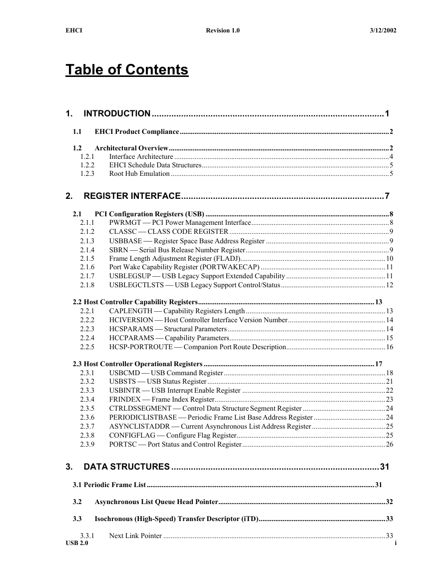
EHCI Revision 1.0 3/12/2002 Table of Contents 1. INTRODUCTION ............................................................................................... 1 1.1 EHCI Product Compliance .................................................................................................................. 2 1.2 Architectural Overview ........................................................................................................................ 2 Interface Architecture ..................................................................................................................... 4 EHCI Schedule Data Structures ...................................................................................................... 5 Root Hub Emulation ....................................................................................................................... 5 1.2.1 1.2.2 1.2.3 2. REGISTER INTERFACE ................................................................................... 7 2.1 PCI Configuration Registers (USB) .................................................................................................... 8 PWRMGT  PCI Power Management Interface ........................................................................... 8 CLASSC  CLASS CODE REGISTER ....................................................................................... 9 USBBASE  Register Space Base Address Register ................................................................... 9 SBRN  Serial Bus Release Number Register .............................................................................. 9 Frame Length Adjustment Register (FLADJ) ............................................................................... 10 Port Wake Capability Register (PORTWAKECAP) .................................................................... 11 USBLEGSUP  USB Legacy Support Extended Capability ...................................................... 11 USBLEGCTLSTS  USB Legacy Support Control/Status ......................................................... 12 2.1.1 2.1.2 2.1.3 2.1.4 2.1.5 2.1.6 2.1.7 2.1.8 2.2 Host Controller Capability Registers ................................................................................................ 13 CAPLENGTH  Capability Registers Length ............................................................................ 13 HCIVERSION  Host Controller Interface Version Number ..................................................... 14 HCSPARAMS  Structural Parameters ...................................................................................... 14 HCCPARAMS  Capability Parameters ..................................................................................... 15 HCSP-PORTROUTE  Companion Port Route Description ...................................................... 16 2.2.1 2.2.2 2.2.3 2.2.4 2.2.5 2.3.1 2.3.2 2.3.3 2.3.4 2.3.5 2.3.6 2.3.7 2.3.8 2.3.9 2.3 Host Controller Operational Registers ............................................................................................. 17 USBCMD  USB Command Register ........................................................................................ 18 USBSTS  USB Status Register ................................................................................................. 21 USBINTR  USB Interrupt Enable Register .............................................................................. 22 FRINDEX  Frame Index Register ............................................................................................. 23 CTRLDSSEGMENT  Control Data Structure Segment Register ............................................. 24 PERIODICLISTBASE  Periodic Frame List Base Address Register ....................................... 24 ASYNCLISTADDR  Current Asynchronous List Address Register ........................................ 25 CONFIGFLAG  Configure Flag Register ................................................................................. 25 PORTSC  Port Status and Control Register .............................................................................. 26 3. DATA STRUCTURES ..................................................................................... 31 3.1 Periodic Frame List ............................................................................................................................ 31 3.2 3.3 Asynchronous List Queue Head Pointer ........................................................................................... 32 Isochronous (High-Speed) Transfer Descriptor (iTD) ..................................................................... 33 3.3.1 USB 2.0 Next Link Pointer ......................................................................................................................... 33 i
EHCI Revision 1.0 3/12/2002 3.3.2 3.3.3 iTD Transaction Status and Control List ...................................................................................... 34 iTD Buffer Page Pointer List (Plus) .............................................................................................. 35 3.4 Split Transaction Isochronous Transfer Descriptor (siTD) ............................................................ 36 Next Link Pointer ......................................................................................................................... 37 siTD Endpoint Capabilities/Characteristics .................................................................................. 37 siTD Transfer State ....................................................................................................................... 38 siTD Buffer Pointer List (plus) ..................................................................................................... 39 siTD Back Link Pointer ................................................................................................................ 40 3.4.1 3.4.2 3.4.3 3.4.4 3.4.5 3.5 Queue Element Transfer Descriptor (qTD) ...................................................................................... 40 Next qTD Pointer .......................................................................................................................... 41 Alternate Next qTD Pointer .......................................................................................................... 41 qTD Token .................................................................................................................................... 42 qTD Buffer Page Pointer List ....................................................................................................... 45 3.5.1 3.5.2 3.5.3 3.5.4 3.6 Queue Head ......................................................................................................................................... 46 Queue Head Horizontal Link Pointer ............................................................................................ 46 Endpoint Capabilities/Characteristics ........................................................................................... 47 Transfer Overlay ........................................................................................................................... 49 3.6.1 3.6.2 3.6.3 3.7 Periodic Frame Span Traversal Node (FSTN) ................................................................................. 51 FSTN Normal Path Pointer ........................................................................................................... 51 FSTN Back Path Link Pointer ...................................................................................................... 52 3.7.1 3.7.2 4. OPERATIONAL MODEL ................................................................................ 53 4.1 Host Controller Initialization ............................................................................................................ 53 4.2 Port Routing and Control. ................................................................................................................. 54 Port Routing Control via EHCI Configured (CF) Bit ................................................................... 55 Port Routing Control via PortOwner and Disconnect Event ........................................................ 56 Example Port Routing State Machine ........................................................................................... 57 Port Power .................................................................................................................................... 57 Port Reporting Over-Current ........................................................................................................ 58 4.2.1 4.2.2 4.2.3 4.2.4 4.2.5 4.3 Suspend/Resume ................................................................................................................................. 59 Port Suspend/Resume ................................................................................................................... 59 4.3.1 4.4 Schedule Traversal Rules ................................................................................................................... 61 Example - Preserving Micro-Frame Integrity ..................................................................... 62 4.4.1 4.5 4.6 Periodic Schedule Frame Boundaries vs Bus Frame Boundaries ................................................... 64 Periodic Schedule ................................................................................................................................ 66 4.7 Managing Isochronous Transfers Using iTDs .................................................................................. 67 Host Controller Operational Model for iTDs ................................................................................ 67 Software Operational Model for iTDs ................................................................................ 69 4.7.1 4.7.2 4.8 Asynchronous Schedule ..................................................................................................................... 71 Adding Queue Heads to Asynchronous Schedule ......................................................................... 71 Removing Queue Heads from Asynchronous Schedule ............................................................... 72 Empty Asynchronous Schedule Detection .................................................................................... 74 4.8.1 4.8.2 4.8.3 4.8.4 4.8.5 4.8.6 Restarting Asynchronous Schedule Before EOF .......................................................................... 74 Asynchronous Schedule Traversal : Start Event ........................................................................... 76 Reclamation Status Bit (USBSTS Register) ....................................................................... 77 USB 2.0 ii
分享到:
收藏