L
A
U
N
A
M
E
C
N
E
R
E
F
E
R
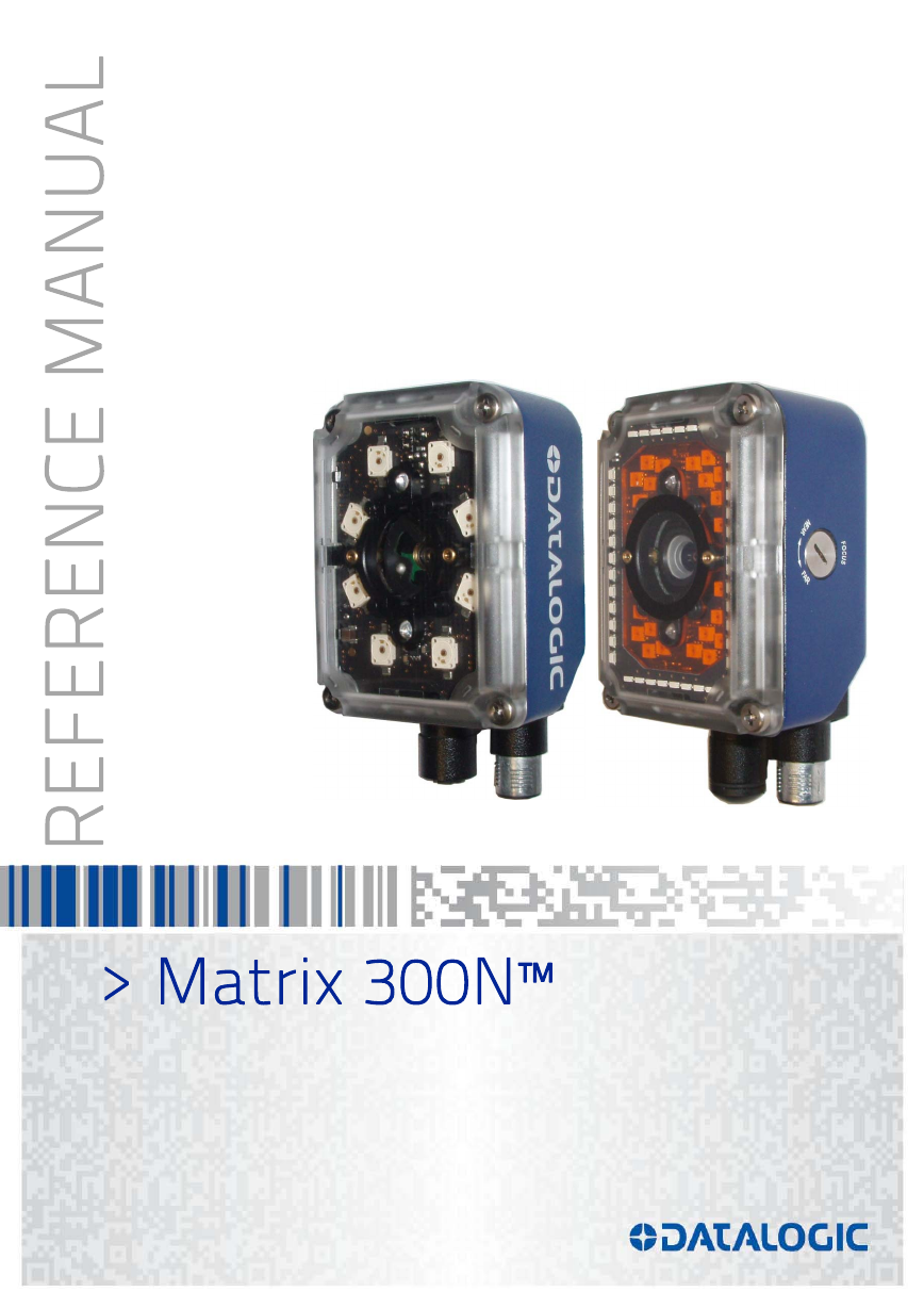
> Matrix 300N™
�
Datalogic Automation s.r.l.
Via Lavino, 265
40050 - Monte S. Pietro
Bologna - Italy
Matrix 300N™ Reference Manual
Ed.: 12/2015
© 2015 Datalogic Automation S.r.l. ALL RIGHTS RESERVED. Protected to the fullest extent under
U.S. and international laws. Copying, or altering of this document is prohibited without express written
consent from Datalogic Automation S.r.l.
Datalogic and the Datalogic logo are registered trademarks of Datalogic S.p.A. in many countries,
including the U.S.A. and the E.U.
Matrix 300N, ID-NET, DL.CODE and X-PRESS are trademarks of Datalogic Automation S.r.l. All other
brand and product names mentioned herein are for identification purposes only and may be
trademarks or registered trademarks of their respective owners.
Datalogic shall not be liable for technical or editorial errors or omissions contained herein, nor for
incidental or consequential damages resulting from the use of this material.
21/12/15
�
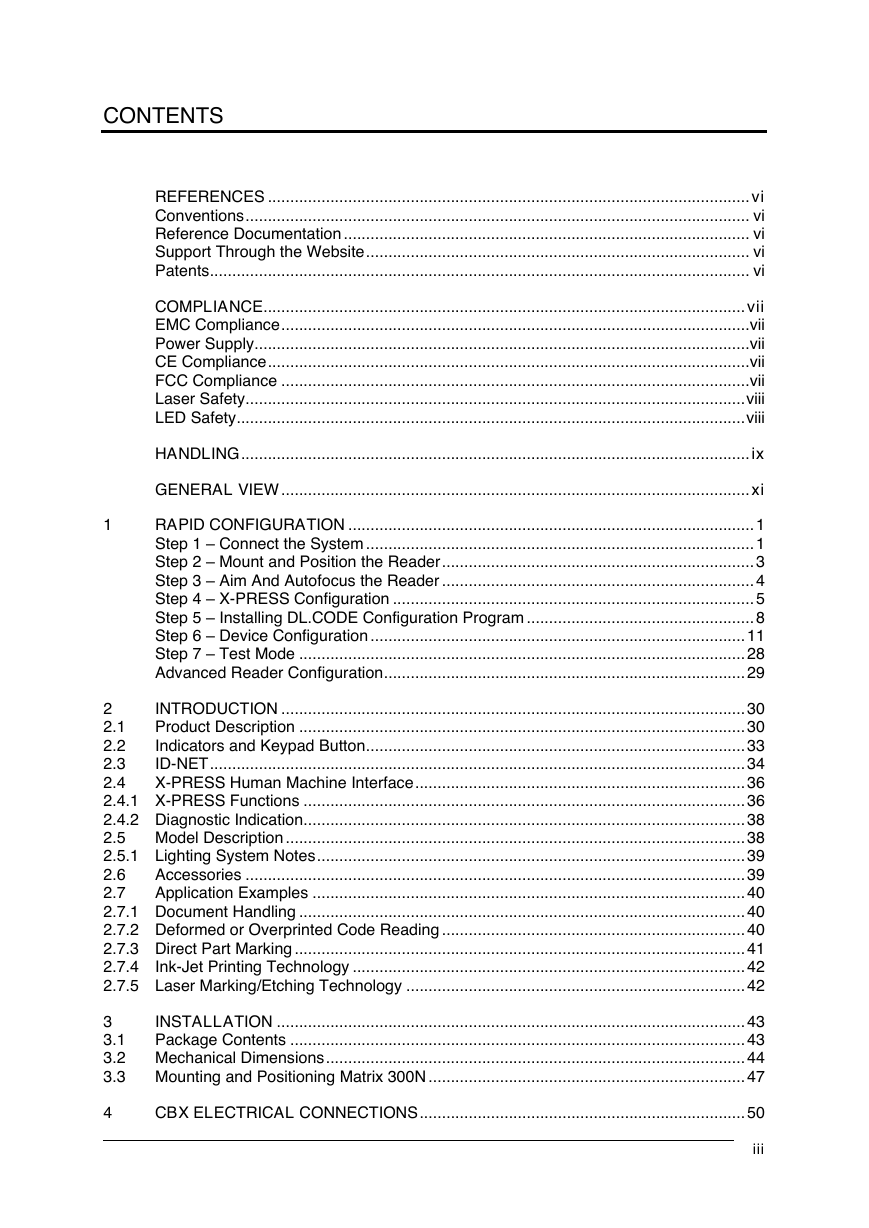
CONTENTS
REFERENCES ............................................................................................................ vi
Conventions ................................................................................................................. vi
Reference Documentation ........................................................................................... vi
Support Through the Website ...................................................................................... vi
Patents ......................................................................................................................... vi
COMPLIANCE ............................................................................................................ vii
EMC Compliance ......................................................................................................... vii
Power Supply ............................................................................................................... vii
CE Compliance ............................................................................................................ vii
FCC Compliance ......................................................................................................... vii
Laser Safety ................................................................................................................ viii
LED Safety .................................................................................................................. viii
HANDLING .................................................................................................................. ix
GENERAL VIEW ......................................................................................................... xi
1
RAPID CONFIGURATION ........................................................................................... 1
Step 1 – Connect the System ....................................................................................... 1
Step 2 – Mount and Position the Reader ...................................................................... 3
Step 3 – Aim And Autofocus the Reader ...................................................................... 4
Step 4 – X-PRESS Configuration ................................................................................. 5
Step 5 – Installing DL.CODE Configuration Program ................................................... 8
Step 6 – Device Configuration .................................................................................... 11
Step 7 – Test Mode .................................................................................................... 28
Advanced Reader Configuration ................................................................................. 29
INTRODUCTION ........................................................................................................ 30
2
Product Description .................................................................................................... 30
2.1
Indicators and Keypad Button ..................................................................................... 33
2.2
ID-NET ........................................................................................................................ 34
2.3
2.4
X-PRESS Human Machine Interface .......................................................................... 36
2.4.1 X-PRESS Functions ................................................................................................... 36
2.4.2 Diagnostic Indication ................................................................................................... 38
2.5 Model Description ....................................................................................................... 38
2.5.1 Lighting System Notes ................................................................................................ 39
Accessories ................................................................................................................ 39
2.6
2.7
Application Examples ................................................................................................. 40
2.7.1 Document Handling .................................................................................................... 40
2.7.2 Deformed or Overprinted Code Reading .................................................................... 40
2.7.3 Direct Part Marking ..................................................................................................... 41
2.7.4
Ink-Jet Printing Technology ........................................................................................ 42
2.7.5 Laser Marking/Etching Technology ............................................................................ 42
INSTALLATION ......................................................................................................... 43
3
3.1
Package Contents ...................................................................................................... 43
3.2 Mechanical Dimensions .............................................................................................. 44
3.3 Mounting and Positioning Matrix 300N ....................................................................... 47
CBX ELECTRICAL CONNECTIONS ......................................................................... 50
iii
4
�
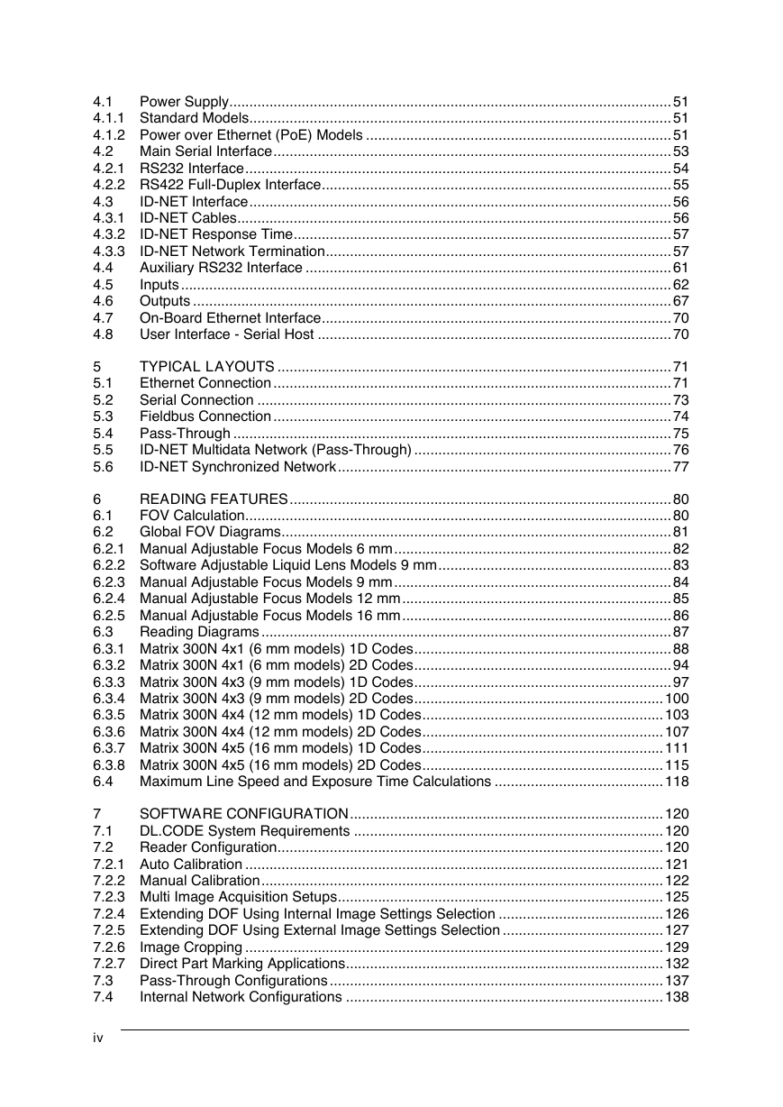
Power Supply .............................................................................................................. 51
4.1
4.1.1 Standard Models ......................................................................................................... 51
4.1.2 Power over Ethernet (PoE) Models ............................................................................ 51
4.2 Main Serial Interface ................................................................................................... 53
4.2.1 RS232 Interface .......................................................................................................... 54
4.2.2 RS422 Full-Duplex Interface ....................................................................................... 55
ID-NET Interface ......................................................................................................... 56
4.3
ID-NET Cables ............................................................................................................ 56
4.3.1
4.3.2
ID-NET Response Time .............................................................................................. 57
ID-NET Network Termination ...................................................................................... 57
4.3.3
Auxiliary RS232 Interface ........................................................................................... 61
4.4
Inputs .......................................................................................................................... 62
4.5
4.6
Outputs ....................................................................................................................... 67
On-Board Ethernet Interface ....................................................................................... 70
4.7
4.8
User Interface - Serial Host ........................................................................................ 70
5
5.1
5.2
5.3
5.4
5.5
5.6
TYPICAL LAYOUTS .................................................................................................. 71
Ethernet Connection ................................................................................................... 71
Serial Connection ....................................................................................................... 73
Fieldbus Connection ................................................................................................... 74
Pass-Through ............................................................................................................. 75
ID-NET Multidata Network (Pass-Through) ................................................................ 76
ID-NET Synchronized Network ................................................................................... 77
READING FEATURES ............................................................................................... 80
6
FOV Calculation .......................................................................................................... 80
6.1
6.2
Global FOV Diagrams ................................................................................................. 81
6.2.1 Manual Adjustable Focus Models 6 mm ..................................................................... 82
6.2.2 Software Adjustable Liquid Lens Models 9 mm .......................................................... 83
6.2.3 Manual Adjustable Focus Models 9 mm ..................................................................... 84
6.2.4 Manual Adjustable Focus Models 12 mm ................................................................... 85
6.2.5 Manual Adjustable Focus Models 16 mm ................................................................... 86
6.3
Reading Diagrams ...................................................................................................... 87
6.3.1 Matrix 300N 4x1 (6 mm models) 1D Codes ................................................................ 88
6.3.2 Matrix 300N 4x1 (6 mm models) 2D Codes ................................................................ 94
6.3.3 Matrix 300N 4x3 (9 mm models) 1D Codes ................................................................ 97
6.3.4 Matrix 300N 4x3 (9 mm models) 2D Codes .............................................................. 100
6.3.5 Matrix 300N 4x4 (12 mm models) 1D Codes ............................................................ 103
6.3.6 Matrix 300N 4x4 (12 mm models) 2D Codes ............................................................ 107
6.3.7 Matrix 300N 4x5 (16 mm models) 1D Codes ............................................................ 111
6.3.8 Matrix 300N 4x5 (16 mm models) 2D Codes ............................................................ 115
6.4 Maximum Line Speed and Exposure Time Calculations .......................................... 118
SOFTWARE CONFIGURATION .............................................................................. 120
7
DL.CODE System Requirements ............................................................................. 120
7.1
7.2
Reader Configuration ................................................................................................ 120
7.2.1 Auto Calibration ........................................................................................................ 121
7.2.2 Manual Calibration .................................................................................................... 122
7.2.3 Multi Image Acquisition Setups ................................................................................. 125
7.2.4 Extending DOF Using Internal Image Settings Selection ......................................... 126
7.2.5 Extending DOF Using External Image Settings Selection ........................................ 127
7.2.6
Image Cropping ........................................................................................................ 129
7.2.7 Direct Part Marking Applications ............................................................................... 132
Pass-Through Configurations ................................................................................... 137
7.3
7.4
Internal Network Configurations ............................................................................... 138
iv
�
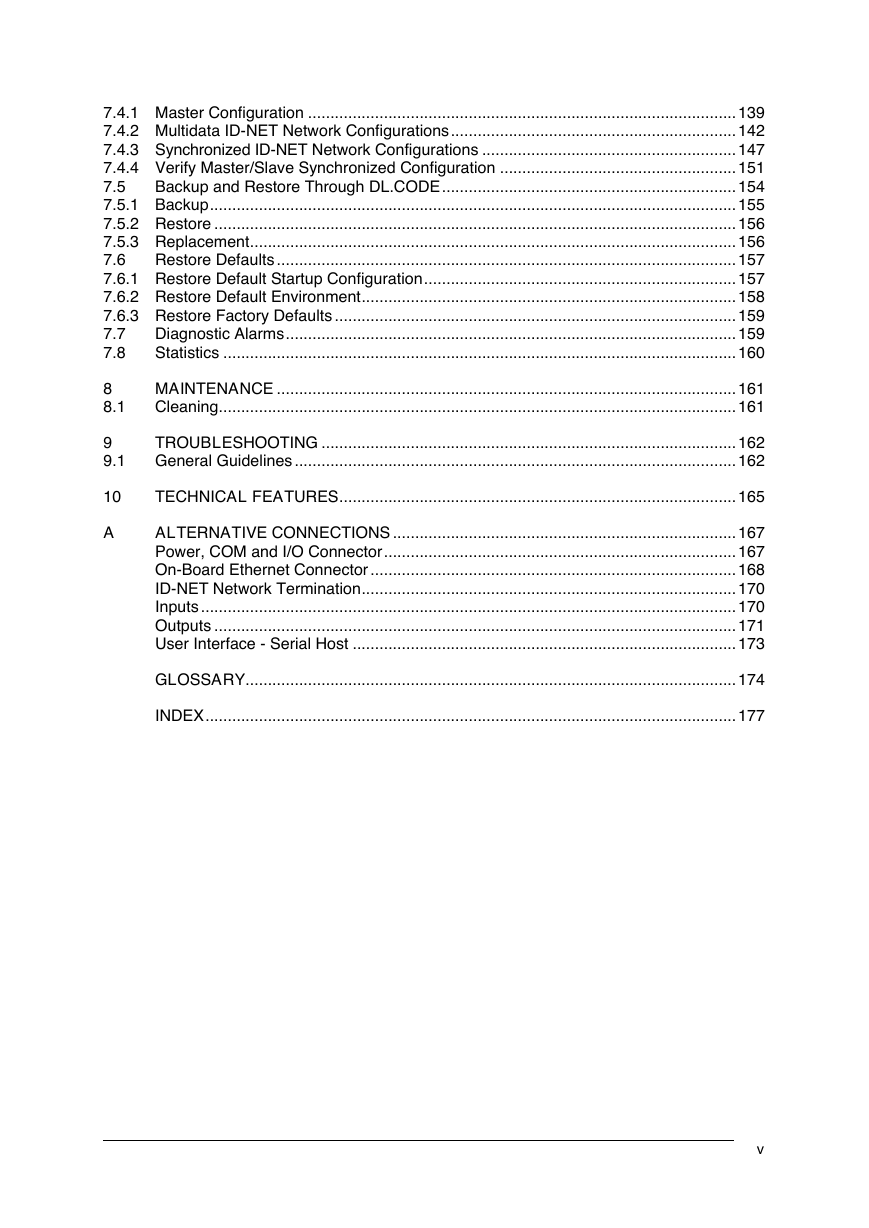
7.4.1 Master Configuration ................................................................................................ 139
7.4.2 Multidata ID-NET Network Configurations ................................................................ 142
7.4.3 Synchronized ID-NET Network Configurations ......................................................... 147
7.4.4 Verify Master/Slave Synchronized Configuration ..................................................... 151
7.5
Backup and Restore Through DL.CODE .................................................................. 154
7.5.1 Backup ...................................................................................................................... 155
7.5.2 Restore ..................................................................................................................... 156
7.5.3 Replacement ............................................................................................................. 156
7.6
Restore Defaults ....................................................................................................... 157
7.6.1 Restore Default Startup Configuration ...................................................................... 157
7.6.2 Restore Default Environment .................................................................................... 158
7.6.3 Restore Factory Defaults .......................................................................................... 159
7.7
Diagnostic Alarms ..................................................................................................... 159
Statistics ................................................................................................................... 160
7.8
8
8.1
9
9.1
MAINTENANCE ....................................................................................................... 161
Cleaning .................................................................................................................... 161
TROUBLESHOOTING ............................................................................................. 162
General Guidelines ................................................................................................... 162
10
TECHNICAL FEATURES ......................................................................................... 165
A
ALTERNATIVE CONNECTIONS ............................................................................. 167
Power, COM and I/O Connector ............................................................................... 167
On-Board Ethernet Connector .................................................................................. 168
ID-NET Network Termination .................................................................................... 170
Inputs ........................................................................................................................ 170
Outputs ..................................................................................................................... 171
User Interface - Serial Host ...................................................................................... 173
GLOSSARY .............................................................................................................. 174
INDEX ....................................................................................................................... 177
v
�
REFERENCES
CONVENTIONS
This manual uses the following conventions:
"User" refers to anyone using a Matrix 300N reader.
"Reader" refers to the Matrix 300N reader.
"You" refers to the System Administrator or Technical Support person using this manual to
install, configure, operate, maintain or troubleshoot a Matrix 300N reader.
REFERENCE DOCUMENTATION
For further details refer to: the DL.CODE™ Help On Line, DL.CODE User’s Guide, Matrix
Reading Methods, provided as supplementary documentation on the DL.CODE mini-DVD
(downloaded .zip file or mini-DVD accessory).
SUPPORT THROUGH THE WEBSITE
Datalogic provides several services as well as technical support through its website. Log on
to www.datalogic.com and click on the Industrial Automation links for further information:
PRODUCTS – FIXED INDUSTRIAL BARCODE READERS
Select your product from the links on the Fixed Industrial Barcode Readers page. The
product page describes specific Info, Features, Applications, Models, Accessories, and
Downloads including documentation, software drivers, and utility programs.
SUPPORT & SERVICES – INDUSTRIAL AUTOMATION
Several links from the Industrial Automation list take you to additional services such as:
Service Program which contains Maintenance Agreements and Warranty Extensions;
Repair Centers; On-Line RMA Return Material Authorizations; Technical Support through
email or phone; Downloads for additional downloads.
PATENTS
See www.patents.datalogic.com for patent list.
This product is covered by one or more of the following patents:
Design patents: EP002197715
patents:
EP0996284B1,
Utility
EP1128315B1,
EP1396811B1, EP1413971B1, JP4435343B2, JP4571258B2, US6512218, US6616039,
US6808114, US6997385, US7053954, US7387246, US8058600, US8368000, US8743263
EP0999514B1,
EP1014292B1,
vi
�
COMPLIANCE
For installation, use and maintenance it is not necessary to open the reader.
Only connect Ethernet and dataport connections to a network which has routing only within the plant
or building and no routing outside the plant or building.
EMC COMPLIANCE
In order to meet the EMC requirements:
connect reader chassis to the plant earth ground by means of a flat copper braid shorter than
100 mm;
connect pin "Earth" of the CBX connection box to a good Earth Ground;
for direct connections, connect your cable shield to the locking ring nut of the connector.
POWER SUPPLY
ATTENTION: READ THIS INFORMATION BEFORE INSTALLING THE PRODUCT
This product is intended to be installed by Qualified Personnel only.
This product is intended to be connected to a UL Listed Computer (LPS or “Class 2”) which supplies
power directly to the reader, or a UL Listed Direct Plug-in Power Unit (rated 10 to 30 V, minimum 1 A)
marked LPS or “Class 2”, or Power over Ethernet source Device supplied by UL Listed Direct Plug-in
Power Unit marked LPS or “Class 2”.
CE COMPLIANCE
Warning: This is a Class A product. In a domestic environment this product may cause radio
interference in which case the user may be required to take adequate measures.
FCC COMPLIANCE
Modifications or changes to this equipment without the expressed written approval of Datalogic could
void the authority to use the equipment.
This device complies with PART 15 of the FCC Rules. Operation is subject to the following two
conditions: (1) This device may not cause harmful interference, and (2) this device must accept any
interference received, including interference which may cause undesired operation.
This equipment has been tested and found to comply with the limits for a Class A digital device,
pursuant to part 15 of the FCC Rules. These limits are designed to provide reasonable protection
against harmful interference when the equipment is operated in a commercial environment. This
equipment generates, uses, and can radiate radio frequency energy and, if not installed and used in
accordance with the instruction manual, may cause harmful interference to radio communications.
Operation of this equipment in a residential area is likely to cause harmful interference in which case
the user will be required to correct the interference at his own expense.
vii
�
LASER SAFETY
The Matrix 300N internal illuminators contain two aiming Laser LEDs used to position the
reader.
This product conforms to the applicable requirements of IEC 60825-1 and complies with 21
CFR 1040.10 except for deviations pursuant to Laser Notice N° 50, date June 24, 2007. This
product is classified as a Class 2 laser product according to IEC 60825-1 regulations.
WARNING: Use of controls or adjustments or performance of procedures
other than those specified herein may result in exposure to hazardous visible
laser light.
Disconnect the power supply when opening the device during maintenance or installation to
avoid exposure to hazardous laser light. The laser beam can be switched on or off through a
software command.
Produit(s) conforme selon 21CFR 1040.10
sauf des dérogations relatives à la Laser
Notice N° 50, date Juin 24, 2007.
le
Dans le paquet il y a l’étiquette(s) pour les
pays où
texte d'avertissement en
français sont obligatoires. Le(s) mettre sur
le produit à
la version
anglaise.
la place de
Matrix 300N Warning Labels
Exemple d'étiquettes d'avertissement laser
LED SAFETY
LED emission according to EN 62471.
viii
�





 2023年江西萍乡中考道德与法治真题及答案.doc
 2012年重庆南川中考生物真题及答案.doc
 2013年江西师范大学地理学综合及文艺理论基础考研真题.doc
 2020年四川甘孜小升初语文真题及答案I卷.doc
 2020年注册岩土工程师专业基础考试真题及答案.doc
 2023-2024学年福建省厦门市九年级上学期数学月考试题及答案.doc
 2021-2022学年辽宁省沈阳市大东区九年级上学期语文期末试题及答案.doc
 2022-2023学年北京东城区初三第一学期物理期末试卷及答案.doc
 2018上半年江西教师资格初中地理学科知识与教学能力真题及答案.doc
 2012年河北国家公务员申论考试真题及答案-省级.doc
 2020-2021学年江苏省扬州市江都区邵樊片九年级上学期数学第一次质量检测试题及答案.doc
 2022下半年黑龙江教师资格证中学综合素质真题及答案.doc