logo资料库

mips32系统架构手册.pdf

第1页 / 共222页
第2页 / 共222页
第3页 / 共222页
第4页 / 共222页
第5页 / 共222页
第6页 / 共222页
第7页 / 共222页
第8页 / 共222页
资料共222页,剩余部分请下载后查看
MIPS32 4K™ Processor Core Family Software User’s Manual
Table of Contents
List of Figures
List of Tables
Introduction to the MIPS32 4K™ Processor Core Family
1.1 Features
1.2 Block Diagram
1.3 Required Logic Blocks
1.3.1 Execution Unit
1.3.2 Multiply/Divide Unit (MDU)
1.3.3 System Control Coprocessor (CP0)
1.3.4 Memory Management Unit (MMU)
1.3.5 Cache Controllers
1.3.6 Bus Interface Unit (BIU)
1.3.7 Power Management
1.4 Optional Logic Blocks
1.4.1 Instruction Cache
1.4.2 Data Cache
1.4.3 EJTAG Controller
Pipeline
2.1 Pipeline Stages
2.1.1 I Stage: Instruction Fetch
2.1.2 E Stage: Execution
2.1.3 M Stage: Memory Fetch
2.1.4 A Stage: Align/Accumulate
2.1.5 W Stage: Writeback
2.2 Instruction Cache Miss
2.3 Data Cache Miss
2.4 Multiply/Divide Operations
2.5 MDU Pipeline (4Kc and 4Km Cores)
2.5.1 32x16 Multiply (4Kc and 4Km Cores)
2.5.2 32x32 Multiply (4Kc and 4Km Cores)
2.5.3 Divide (4Kc and 4Km Cores)
2.6 MDU Pipeline (4Kp Core Only)
2.6.1 Multiply (4Kp Core)
2.6.2 Multiply Accumulate (4Kp Core)
2.6.3 Divide (4Kp Core)
2.7 Branch Delay
2.8 Data Bypassing
2.8.1 Load Delay
2.8.2 Move from HI/LO and CP0 Delay
2.9 Interlock Handling
2.10 Slip Conditions
2.11 Instruction Interlocks
2.12 Instruction Hazards
Memory Management
3.1 Introduction
3.2 Modes of Operation
3.2.1 Virtual Memory Segments
3.2.1.1 Unmapped Segments
3.2.1.2 Mapped Segments
3.2.2 User Mode
3.2.3 Kernel Mode
3.2.3.1 Kernel Mode, User Space (kuseg)
3.2.3.2 Kernel Mode, Kernel Space 0 (kseg0)
3.2.3.3 Kernel Mode, Kernel Space 1 (kseg1)
3.2.3.4 Kernel Mode, Kernel Space 2 (kseg2)
3.2.3.5 Kernel Mode, Kernel Space 3 (kseg3)
3.2.4 Debug Mode
3.2.4.1 Conditions and Behavior for Access to drseg, EJTAG Registers
3.2.4.2 Conditions and Behavior for Access to dmseg, EJTAG Memory
3.3 Translation Lookaside Buffer (4Kc Core Only)
3.3.1 Joint TLB
3.3.2 Instruction TLB
3.3.3 Data TLB
3.4 Virtual to Physical Address Translation (4Kc Core)
3.4.1 Hits, Misses, and Multiple Matches
3.4.2 Page Sizes and Replacement Algorithm
3.4.3 TLB Instructions
3.5 Fixed Mapping MMU (4Km & 4Kp Cores)
3.6 System Control Coprocessor
Exceptions
4.1 Exception Conditions
4.2 Exception Priority
4.3 Exception Vector Locations
4.4 General Exception Processing
4.5 Debug Exception Processing
4.6 Exceptions
4.6.1 Reset Exception
4.6.2 Soft Reset Exception
4.6.3 Debug Single Step Exception
4.6.4 Debug Interrupt Exception
4.6.5 Non-Maskable Interrupt (NMI) Exception
4.6.6 Machine Check Exception (4Kc core)
4.6.7 Interrupt Exception
4.6.8 Debug Instruction Break Exception
4.6.9 Watch Exception — Instruction Fetch or Data Access
4.6.10 Address Error Exception — Instruction Fetch/Data Access
4.6.11 TLB Refill Exception — Instruction Fetch or Data Access (4Kc core)
4.6.12 TLB Invalid Exception — Instruction Fetch or Data Access (4Kc core)
4.6.13 Bus Error Exception — Instruction Fetch or Data Access
4.6.14 Debug Software Breakpoint Exception
4.6.15 Execution Exception — System Call
4.6.16 Execution Exception — Breakpoint
4.6.17 Execution Exception — Reserved Instruction
4.6.18 Execution Exception — Coprocessor Unusable
4.6.19 Execution Exception — Integer Overflow
4.6.20 Execution Exception — Trap
4.6.21 Debug Data Break Exception
4.6.22 TLB Modified Exception — Data Access (4Kc core)
4.7 Exception Handling and Servicing Flowcharts
CP0 Registers
5.1 CP0 Register Summary
5.2 CP0 Registers
5.2.1 Index Register (CP0 Register 0, Select 0)
5.2.2 Random Register (CP0 Register 1, Select 0)
5.2.3 EntryLo0, EntryLo1 (CP0 Registers 2 and 3, Select 0)
5.2.4 Context Register (CP0 Register 4, Select 0)
5.2.5 PageMask Register (CP0 Register 5, Select 0)
5.2.6 Wired Register (CP0 Register 6, Select 0)
5.2.7 BadVAddr Register (CP0 Register 8, Select 0)
5.2.8 Count Register (CP0 Register 9, Select 0)
5.2.9 EntryHi Register (CP0 Register 10, Select 0)
5.2.10 Compare Register (CP0 Register 11, Select 0)
5.2.11 Status Register (CP0 Register 12, Select 0)
5.2.12 Cause Register (CP0 Register 13, Select 0)
5.2.13 Exception Program Counter (CP0 Register 14, Select 0)
5.2.14 Processor Identification (CP0 Register 15, Select 0)
5.2.15 Config Register (CP0 Register 16, Select 0)
5.2.16 Config1 Register (CP0 Register 16, Select 1)
5.2.17 Load Linked Address (CP0 Register 17, Select 0)
5.2.18 WatchLo Register (CP0 Register 18)
5.2.19 WatchHi Register (CP0 Register 19)
5.2.20 Debug Register (CP0 Register 23)
5.2.21 Debug Exception Program Counter Register (CP0 Register 24)
5.2.22 ErrCtl Register (CP0 Register 26, Select 0)
5.2.23 TagLo Register (CP0 Register 28, Select 0)
5.2.24 DataLo Register (CP0 Register 28, Select 1)
5.2.25 ErrorEPC (CP0 Register 30, Select 0)
5.2.26 DeSave Register (CP0 Register 31)
Hardware and Software Initialization
6.1 Hardware Initialized Processor State
6.1.1 Coprocessor Zero State
6.1.2 TLB Initialization (4Kc core only)
6.1.3 Bus State Machines
6.1.4 Static Configuration Inputs
6.1.5 Fetch Address
6.2 Software Initialized Processor State
6.2.1 Register File
6.2.2 TLB (4Kc Core Only)
6.2.3 Caches
6.2.4 Coprocessor Zero state
Caches
7.1 Introduction
7.2 Cache Protocols
7.2.1 Cache Organization
7.2.2 Cacheability Attributes
7.2.3 Replacement Policy
7.3 Instruction Cache
7.4 Data Cache
7.5 Memory Coherence Issues
Power Management
8.1 Register-Controlled Power Management
8.2 Instruction-Controlled Power Management
EJTAG Debug Support
9.1 Debug Control Register
9.2 Hardware Breakpoints
9.2.1 Features of Instruction Breakpoint
9.2.2 Features of Data Breakpoint
9.2.3 Overview of Registers for Instruction Breakpoints
9.2.4 Registers for Data Breakpoint Setup
9.2.5 Conditions for Matching Breakpoints
9.2.5.1 Conditions for Matching Instruction Breakpoint
9.2.5.2 Conditions for Matching Data Breakpoints
9.2.6 Debug Exceptions from Breakpoints
9.2.6.1 Debug Exception by Instruction Breakpoint
9.2.6.2 Debug Exception by Data Breakpoint
9.2.7 Breakpoint used as Triggerpoint
9.2.8 Instruction Breakpoint Registers
9.2.8.1 Instruction Breakpoint Status (IBS) Register
9.2.8.2 Instruction Breakpoint Address n (IBAn) Register
9.2.8.3 Instruction Breakpoint Address Mask n (IBMn) Register
9.2.8.4 Instruction Breakpoint ASID n (IBASIDn) Register
9.2.8.5 Instruction Breakpoint Control n (IBCn) Register
9.2.9 Data Breakpoint Registers
9.2.9.1 Data Breakpoint Status (DBS) Register
9.2.9.2 Data Breakpoint Address n (DBAn) Register
9.2.9.3 Data Breakpoint Address Mask n (DBMn) Register
9.2.9.4 Data Breakpoint ASID n (DBASIDn) Register
9.2.9.5 Data Breakpoint Control n (DBCn) Register
9.2.9.6 Data Breakpoint Value n (DBVn) Register
9.3 Test Access Port (TAP)
9.3.1 EJTAG Internal and External Interfaces
9.3.2 Test Access Port Operation
9.3.2.1 Test-Logic-Reset State
9.3.2.2 Run-Test/Idle State
9.3.2.3 Select_DR_Scan State
9.3.2.4 Select_IR_Scan State
9.3.2.5 Capture_DR State
9.3.2.6 Shift_DR State
9.3.2.7 Exit1_DR State
9.3.2.8 Pause_DR State
9.3.2.9 Exit2_DR State
9.3.2.10 Update_DR State
9.3.2.11 Capture_IR State
9.3.2.12 Shift_IR State
9.3.2.13 Exit1_IR State
9.3.2.14 Pause_IR State
9.3.2.15 Exit2_IR State
9.3.2.16 Update_IR State
9.3.3 Test Access Port (TAP) Instructions
9.3.3.1 BYPASS Instruction
9.3.3.2 IDCODE Instruction
9.3.3.3 IMPCODE Instruction
9.3.3.4 ADDRESS Instruction
9.3.3.5 DATA Instruction
9.3.3.6 CONTROL Instruction
9.3.3.7 ALL Instruction
9.3.3.8 EJTAGBOOT Instruction
9.3.3.9 NORMALBOOT Instruction
9.3.3.10 FASTDATA Instruction
9.4 EJTAG TAP Registers
9.4.1 Instruction Register
9.4.2 Data Registers Overview
9.4.2.1 Bypass Register
9.4.2.2 Device Identification (ID) Register
9.4.2.3 Implementation Register
9.4.2.4 EJTAG Control Register
9.4.3 Processor Access Address Register
9.4.3.1 Processor Access Data Register
9.4.4 Fastdata Register (TAP Instruction FASTDATA)
9.5 Processor Accesses
9.5.1 Fetch/Load and Store from/to the EJTAG Probe through dmseg
Instruction Set Overview
10.1 CPU Instruction Formats
10.2 Load and Store Instructions
10.2.1 Scheduling a Load Delay Slot
10.2.2 Defining Access Types
10.3 Computational Instructions
10.3.1 Cycle Timing for Multiply and Divide Instructions
10.4 Jump and Branch Instructions
10.4.1 Overview of Jump Instructions
10.4.2 Overview of Branch Instructions
10.5 Control Instructions
10.6 Coprocessor Instructions
10.7 Enhancements to the MIPS Architecture
10.7.1 CLO - Count Leading Ones
10.7.2 CLZ - Count Leading Zeros
10.7.3 MADD - Multiply and Add Word
10.7.4 MADDU - Multiply and Add Unsigned Word
10.7.5 MSUB - Multiply and Subtract Word
10.7.6 MSUBU - Multiply and Subtract Unsigned Word
10.7.7 MUL - Multiply Word
10.7.8 SSNOP- Superscalar Inhibit NOP
MIPS32 4K Processor Core Instructions
11.1 Understanding the Instruction Descriptions
11.2 CPU Opcode Map
11.3 Instruction Set
CACHE
LL
PREF
SC
SYNC
TLBR
TLBWI
TLBWR
WAIT
Revision History
MIPS32 4K™ Processor Core Family Software User’s Manual Document Number: MD00016 Revision 01.17 September 25, 2002 MIPS Technologies, Inc. 1225 Charleston Road Mountain View, CA 94043-1353 Copyright © 1998-2002 MIPS Technologies Inc. All rights reserved.
Copyright © 1998-2002 MIPS Technologies, Inc. All rights reserved. Unpublished rights (if any) are reserved under the Copyright Laws of the United States of America. If this document is provided in source format (i.e., in a modifiable form such as in FrameMaker or Microsoft Word format), then its use and distribution is subject to a written agreement with MIPS Technologies, Inc. ("MIPS Technologies"). UNDER NO CIRCUMSTANCES MAY A DOCUMENT PROVIDED IN SOURCE FORMAT BE DISTRIBUTED TO A THIRD PARTY WITHOUT THE EXPRESS WRITTEN CONSENT OF MIPS TECHNOLOGIES. This document contains information that is proprietary to MIPS Technologies. Any copying, reproducing, modifying, or use of this information (in whole or in part) which is not expressly permitted in writing by MIPS Technologies or a contractually-authorized third party is strictly prohibited. At a minimum, this information is protected under unfair competition and copyright laws. Violations thereof may result in criminal penalties and fines. MIPS Technologies or any contractually-authorized third party reserves the right to change the information contained in this document to improve function, design or otherwise. MIPS Technologies does not assume any liability arising out of the application or use of this information, or of any error of omission in such information. Any warranties, whether express, statutory, implied or otherwise, including but not limited to the implied warranties of merchantability or fitness for a particular purpose, are excluded. Any license under patent rights or any other intellectual property rights owned by MIPS Technologies or third parties shall be conveyed by MIPS Technologies or any contractually-authorized third party in a separate license agreement between the parties. The information contained in this document shall not be exported or transferred for the purpose of reexporting in violation of any U.S. or non-U.S. regulation, treaty, Executive Order, law, statute, amendment or supplement thereto. The information contained in this document constitutes one or more of the following: commercial computer software, commercial computer software documentation or other commercial items. If the user of this information, or any related documentation of any kind, including related technical data or manuals, is an agency, department, or other entity of the United States government (“Government”), the use, duplication, reproduction, release, modification, disclosure, or transfer of this information, or any related documentation of any kind, is restricted in accordance with Federal Acquisition Regulation 12.212 for civilian agencies and Defense Federal Acquisition Regulation Supplement 227.7202 for military agencies. The use of this information by the Government is further restricted in accordance with the terms of the license agreement(s) and/or applicable contract terms and conditions covering this information from MIPS Technologies or any contractually-authorized third party. MIPS®, R3000®, R4000®, R5000® and R10000® are among the registered trademarks of MIPS Technologies, Inc. in the United States and certain other countries, and MIPS16™, MIPS16e™, MIPS32™, MIPS64™, MIPS-3D™, MIPS-based™, MIPS I™, MIPS II™, MIPS III™, MIPS IV™, MIPS V™, MDMX™, MIPSsim™, MIPSsimCA™, MIPSsimIA™, QuickMIPS™, SmartMIPS™, MIPS Technologies logo, 4K™, 4Kc™, 4Km™, 4Kp™, 4KE™, 4KEc™, 4KEm™, 4KEp™, 4KS™, 4KSc™, M4K™, 5K™, 5Kc™, 5Kf™, 20K™, 20Kc™, 25Kf™, R4300™, ASMACRO™, ATLAS™, BusBridge™, CoreFPGA™, CoreLV™, EC™, JALGO™, MALTA™, MGB™, PDtrace™, SEAD™, SEAD-2™, SOC-it™, The Pipeline™, and YAMON™ are among the trademarks of MIPS Technologies, Inc. All other trademarks referred to herein are the property of their respective owners. Template: B1.06, Build with Conditional Tags: 2B JADE MIPS32 PROC MIPS32 4K™ Processor Core Family Software User’s Manual, Revision 01.17 Copyright © 1998-2002 MIPS Technologies Inc. All rights reserved.
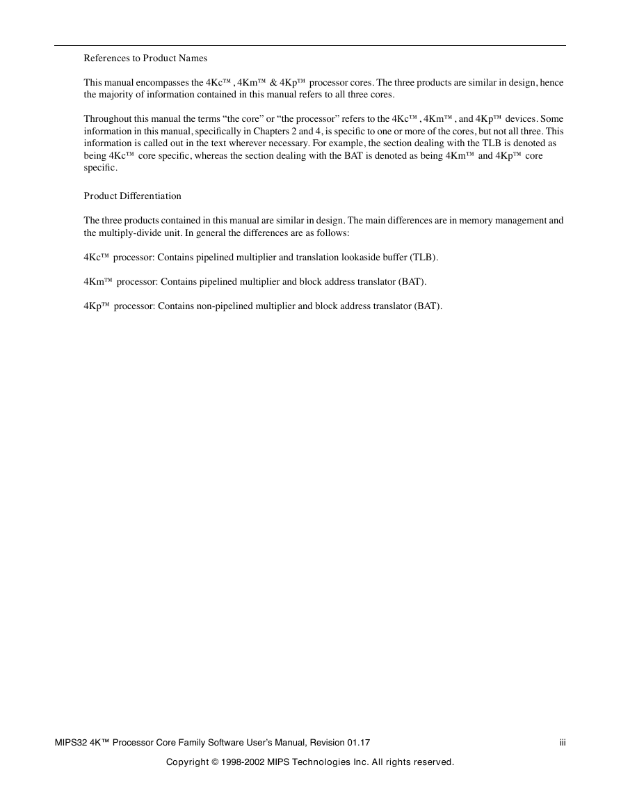
References to Product Names This manual encompasses the 4Kc™, 4Km™ & 4Kp™ processor cores. The three products are similar in design, hence the majority of information contained in this manual refers to all three cores. Throughout this manual the terms “the core” or “the processor” refers to the 4Kc™, 4Km™, and 4Kp™ devices. Some information in this manual, specifically in Chapters 2 and 4, is specific to one or more of the cores, but not all three. This information is called out in the text wherever necessary. For example, the section dealing with the TLB is denoted as being 4Kc™ core specific, whereas the section dealing with the BAT is denoted as being 4Km™ and 4Kp™ core specific. Product Differentiation The three products contained in this manual are similar in design. The main differences are in memory management and the multiply-divide unit. In general the differences are as follows: 4Kc™ processor: Contains pipelined multiplier and translation lookaside buffer (TLB). 4Km™ processor: Contains pipelined multiplier and block address translator (BAT). 4Kp™ processor: Contains non-pipelined multiplier and block address translator (BAT). MIPS32 4K™ Processor Core Family Software User’s Manual, Revision 01.17 iii Copyright © 1998-2002 MIPS Technologies Inc. All rights reserved.
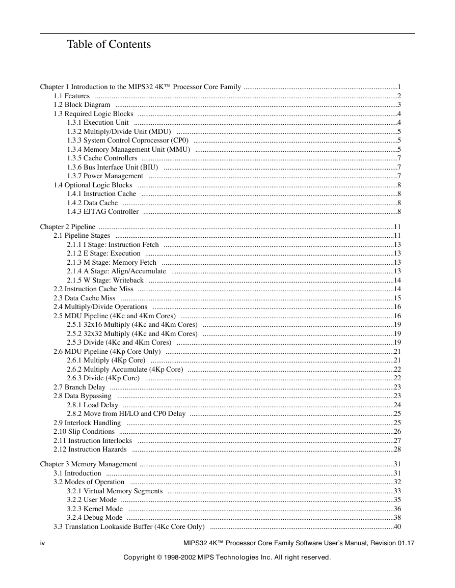
Table of Contents Chapter 1 Introduction to the MIPS32 4K™ Processor Core Family ...................................................................................1 1.1 Features ...................................................................................................................................................................2 1.2 Block Diagram ........................................................................................................................................................3 1.3 Required Logic Blocks ............................................................................................................................................4 ..............................................................................................................................................4 1.3.1 Execution Unit .......................................................................................................................5 1.3.2 Multiply/Divide Unit (MDU) 1.3.3 System Control Coprocessor (CP0) ..............................................................................................................5 1.3.4 Memory Management Unit (MMU) .............................................................................................................5 1.3.5 Cache Controllers ..........................................................................................................................................7 1.3.6 Bus Interface Unit (BIU) ..............................................................................................................................7 ......................................................................................................................................7 1.3.7 Power Management 1.4 Optional Logic Blocks ............................................................................................................................................8 1.4.1 Instruction Cache ..........................................................................................................................................8 1.4.2 Data Cache ....................................................................................................................................................8 1.4.3 EJTAG Controller .........................................................................................................................................8 Chapter 2 Pipeline ...............................................................................................................................................................11 2.1 Pipeline Stages ......................................................................................................................................................11 2.1.1 I Stage: Instruction Fetch ............................................................................................................................13 2.1.2 E Stage: Execution ......................................................................................................................................13 2.1.3 M Stage: Memory Fetch .............................................................................................................................13 2.1.4 A Stage: Align/Accumulate ........................................................................................................................13 2.1.5 W Stage: Writeback ....................................................................................................................................14 2.2 Instruction Cache Miss ..........................................................................................................................................14 2.3 Data Cache Miss ...................................................................................................................................................15 2.4 Multiply/Divide Operations ..................................................................................................................................16 2.5 MDU Pipeline (4Kc and 4Km Cores) ...................................................................................................................16 2.5.1 32x16 Multiply (4Kc and 4Km Cores) .......................................................................................................19 2.5.2 32x32 Multiply (4Kc and 4Km Cores) .......................................................................................................19 2.5.3 Divide (4Kc and 4Km Cores) .....................................................................................................................19 2.6 MDU Pipeline (4Kp Core Only) ...........................................................................................................................21 2.6.1 Multiply (4Kp Core) ...................................................................................................................................21 2.6.2 Multiply Accumulate (4Kp Core) ...............................................................................................................22 2.6.3 Divide (4Kp Core) ......................................................................................................................................22 2.7 Branch Delay .........................................................................................................................................................23 2.8 Data Bypassing .....................................................................................................................................................23 2.8.1 Load Delay ..................................................................................................................................................24 2.8.2 Move from HI/LO and CP0 Delay ..............................................................................................................25 2.9 Interlock Handling ................................................................................................................................................25 2.10 Slip Conditions ....................................................................................................................................................26 2.11 Instruction Interlocks ..........................................................................................................................................27 2.12 Instruction Hazards .............................................................................................................................................28 Chapter 3 Memory Management .........................................................................................................................................31 3.1 Introduction ...........................................................................................................................................................31 3.2 Modes of Operation ..............................................................................................................................................32 3.2.1 Virtual Memory Segments ..........................................................................................................................33 3.2.2 User Mode ...................................................................................................................................................35 3.2.3 Kernel Mode ...............................................................................................................................................36 3.2.4 Debug Mode ................................................................................................................................................38 ...................................................................................................40 3.3 Translation Lookaside Buffer (4Kc Core Only) iv MIPS32 4K™ Processor Core Family Software User’s Manual, Revision 01.17 Copyright © 1998-2002 MIPS Technologies Inc. All right reserved.
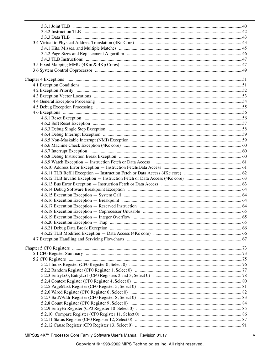
3.4 Virtual to Physical Address Translation (4Kc Core) 3.3.1 Joint TLB ....................................................................................................................................................40 3.3.2 Instruction TLB ...........................................................................................................................................42 3.3.3 Data TLB ....................................................................................................................................................43 ............................................................................................43 3.4.1 Hits, Misses, and Multiple Matches ............................................................................................................45 3.4.2 Page Sizes and Replacement Algorithm .....................................................................................................46 3.4.3 TLB Instructions .........................................................................................................................................47 3.5 Fixed Mapping MMU (4Km & 4Kp Cores) .........................................................................................................47 3.6 System Control Coprocessor .................................................................................................................................49 Chapter 4 Exceptions ..........................................................................................................................................................51 4.1 Exception Conditions ............................................................................................................................................51 4.2 Exception Priority .................................................................................................................................................52 4.3 Exception Vector Locations ..................................................................................................................................53 4.4 General Exception Processing ..............................................................................................................................54 4.5 Debug Exception Processing ................................................................................................................................55 4.6 Exceptions .............................................................................................................................................................56 4.6.1 Reset Exception ..........................................................................................................................................56 4.6.2 Soft Reset Exception ...................................................................................................................................57 4.6.3 Debug Single Step Exception .....................................................................................................................58 4.6.4 Debug Interrupt Exception ..........................................................................................................................59 4.6.5 Non-Maskable Interrupt (NMI) Exception .................................................................................................59 4.6.6 Machine Check Exception (4Kc core) ........................................................................................................60 4.6.7 Interrupt Exception .....................................................................................................................................60 4.6.8 Debug Instruction Break Exception ............................................................................................................60 4.6.9 Watch Exception — Instruction Fetch or Data Access ..............................................................................61 4.6.10 Address Error Exception — Instruction Fetch/Data Access .....................................................................61 4.6.11 TLB Refill Exception — Instruction Fetch or Data Access (4Kc core) ...................................................62 4.6.12 TLB Invalid Exception — Instruction Fetch or Data Access (4Kc core) .................................................63 4.6.13 Bus Error Exception — Instruction Fetch or Data Access .......................................................................63 4.6.14 Debug Software Breakpoint Exception ....................................................................................................64 4.6.15 Execution Exception — System Call ........................................................................................................64 4.6.16 Execution Exception — Breakpoint .........................................................................................................64 4.6.17 Execution Exception — Reserved Instruction ..........................................................................................64 4.6.18 Execution Exception — Coprocessor Unusable .......................................................................................65 4.6.19 Execution Exception — Integer Overflow ...............................................................................................65 4.6.20 Execution Exception — Trap ....................................................................................................................65 4.6.21 Debug Data Break Exception ....................................................................................................................66 4.6.22 TLB Modified Exception — Data Access (4Kc core) ..............................................................................66 4.7 Exception Handling and Servicing Flowcharts .....................................................................................................67 Chapter 5 CP0 Registers .....................................................................................................................................................73 5.1 CP0 Register Summary .........................................................................................................................................73 5.2 CP0 Registers ........................................................................................................................................................75 5.2.1 Index Register (CP0 Register 0, Select 0) ...................................................................................................76 ..............................................................................................77 5.2.2 Random Register (CP0 Register 1, Select 0) 5.2.3 EntryLo0, EntryLo1 (CP0 Registers 2 and 3, Select 0) ..............................................................................78 5.2.4 Context Register (CP0 Register 4, Select 0) ...............................................................................................80 5.2.5 PageMask Register (CP0 Register 5, Select 0) ...........................................................................................81 5.2.6 Wired Register (CP0 Register 6, Select 0) ..................................................................................................82 5.2.7 BadVAddr Register (CP0 Register 8, Select 0) ...........................................................................................83 5.2.8 Count Register (CP0 Register 9, Select 0) ..................................................................................................84 5.2.9 EntryHi Register (CP0 Register 10, Select 0) .............................................................................................85 5.2.10 Compare Register (CP0 Register 11, Select 0) ........................................................................................86 5.2.11 Status Register (CP0 Register 12, Select 0) ..............................................................................................87 5.2.12 Cause Register (CP0 Register 13, Select 0) ..............................................................................................91 MIPS32 4K™ Processor Core Family Software User’s Manual, Revision 01.17 v Copyright © 1998-2002 MIPS Technologies Inc. All right reserved.
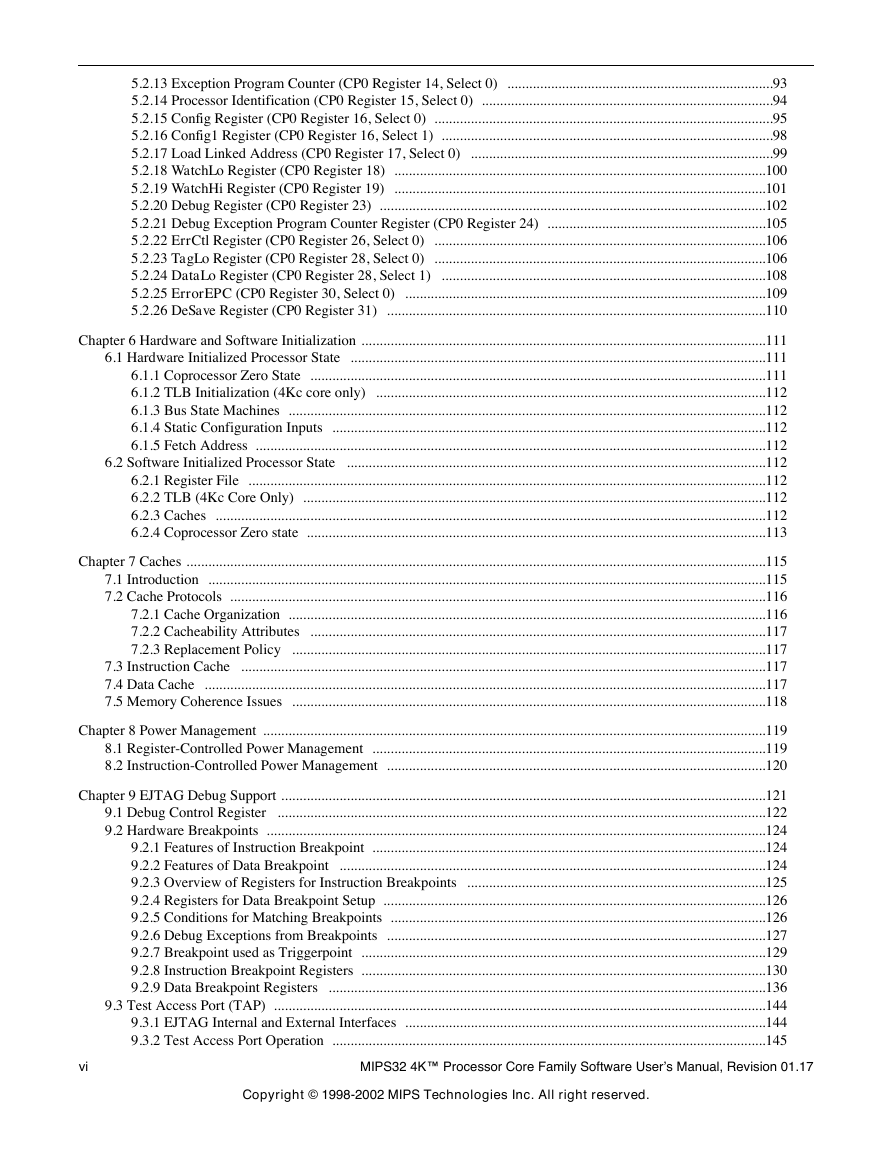
5.2.13 Exception Program Counter (CP0 Register 14, Select 0) .........................................................................93 5.2.14 Processor Identification (CP0 Register 15, Select 0) ................................................................................94 5.2.15 Config Register (CP0 Register 16, Select 0) .............................................................................................95 5.2.16 Config1 Register (CP0 Register 16, Select 1) ...........................................................................................98 5.2.17 Load Linked Address (CP0 Register 17, Select 0) ...................................................................................99 5.2.18 WatchLo Register (CP0 Register 18) ......................................................................................................100 5.2.19 WatchHi Register (CP0 Register 19) ......................................................................................................101 5.2.20 Debug Register (CP0 Register 23) ..........................................................................................................102 5.2.21 Debug Exception Program Counter Register (CP0 Register 24) ............................................................105 5.2.22 ErrCtl Register (CP0 Register 26, Select 0) ...........................................................................................106 5.2.23 TagLo Register (CP0 Register 28, Select 0) ...........................................................................................106 5.2.24 DataLo Register (CP0 Register 28, Select 1) .........................................................................................108 5.2.25 ErrorEPC (CP0 Register 30, Select 0) ...................................................................................................109 5.2.26 DeSave Register (CP0 Register 31) ........................................................................................................110 Chapter 6 Hardware and Software Initialization ...............................................................................................................111 6.1 Hardware Initialized Processor State ..................................................................................................................111 6.1.1 Coprocessor Zero State .............................................................................................................................111 6.1.2 TLB Initialization (4Kc core only) ...........................................................................................................112 6.1.3 Bus State Machines ...................................................................................................................................112 6.1.4 Static Configuration Inputs .......................................................................................................................112 6.1.5 Fetch Address ............................................................................................................................................112 6.2 Software Initialized Processor State ...................................................................................................................112 6.2.1 Register File ..............................................................................................................................................112 6.2.2 TLB (4Kc Core Only) ...............................................................................................................................112 6.2.3 Caches .......................................................................................................................................................112 6.2.4 Coprocessor Zero state ..............................................................................................................................113 Chapter 7 Caches ...............................................................................................................................................................115 7.1 Introduction .........................................................................................................................................................115 7.2 Cache Protocols ...................................................................................................................................................116 7.2.1 Cache Organization ...................................................................................................................................116 7.2.2 Cacheability Attributes .............................................................................................................................117 7.2.3 Replacement Policy ..................................................................................................................................117 7.3 Instruction Cache ................................................................................................................................................117 7.4 Data Cache ..........................................................................................................................................................117 7.5 Memory Coherence Issues ..................................................................................................................................118 Chapter 8 Power Management ..........................................................................................................................................119 ............................................................................................................119 ........................................................................................................120 8.1 Register-Controlled Power Management 8.2 Instruction-Controlled Power Management Chapter 9 EJTAG Debug Support .....................................................................................................................................121 9.1 Debug Control Register ......................................................................................................................................122 9.2 Hardware Breakpoints .........................................................................................................................................124 9.2.1 Features of Instruction Breakpoint ............................................................................................................124 9.2.2 Features of Data Breakpoint .....................................................................................................................124 9.2.3 Overview of Registers for Instruction Breakpoints ..................................................................................125 9.2.4 Registers for Data Breakpoint Setup .........................................................................................................126 9.2.5 Conditions for Matching Breakpoints .......................................................................................................126 9.2.6 Debug Exceptions from Breakpoints ........................................................................................................127 9.2.7 Breakpoint used as Triggerpoint ...............................................................................................................129 9.2.8 Instruction Breakpoint Registers ...............................................................................................................130 9.2.9 Data Breakpoint Registers ........................................................................................................................136 9.3 Test Access Port (TAP) .......................................................................................................................................144 9.3.1 EJTAG Internal and External Interfaces ...................................................................................................144 9.3.2 Test Access Port Operation .......................................................................................................................145 vi MIPS32 4K™ Processor Core Family Software User’s Manual, Revision 01.17 Copyright © 1998-2002 MIPS Technologies Inc. All right reserved.
9.3.3 Test Access Port (TAP) Instructions .........................................................................................................148 9.4 EJTAG TAP Registers ........................................................................................................................................150 9.4.1 Instruction Register ...................................................................................................................................150 9.4.2 Data Registers Overview ..........................................................................................................................151 ..........................................................................................................157 9.4.3 Processor Access Address Register 9.4.4 Fastdata Register (TAP Instruction FASTDATA) ...................................................................................158 9.5 Processor Accesses .............................................................................................................................................159 9.5.1 Fetch/Load and Store from/to the EJTAG Probe through dmseg .............................................................160 Chapter 10 Instruction Set Overview ................................................................................................................................163 10.1 CPU Instruction Formats ..................................................................................................................................163 10.2 Load and Store Instructions ..............................................................................................................................164 10.2.1 Scheduling a Load Delay Slot .................................................................................................................164 10.2.2 Defining Access Types ...........................................................................................................................164 10.3 Computational Instructions ...............................................................................................................................165 10.3.1 Cycle Timing for Multiply and Divide Instructions ...............................................................................165 10.4 Jump and Branch Instructions ...........................................................................................................................166 10.4.1 Overview of Jump Instructions ...............................................................................................................166 10.4.2 Overview of Branch Instructions ............................................................................................................166 10.5 Control Instructions ...........................................................................................................................................166 10.6 Coprocessor Instructions ...................................................................................................................................166 10.7 Enhancements to the MIPS Architecture ..........................................................................................................166 10.7.1 CLO - Count Leading Ones ....................................................................................................................167 10.7.2 CLZ - Count Leading Zeros ....................................................................................................................167 10.7.3 MADD - Multiply and Add Word ..........................................................................................................167 10.7.4 MADDU - Multiply and Add Unsigned Word .......................................................................................167 10.7.5 MSUB - Multiply and Subtract Word .....................................................................................................167 10.7.6 MSUBU - Multiply and Subtract Unsigned Word .................................................................................167 10.7.7 MUL - Multiply Word ............................................................................................................................168 10.7.8 SSNOP- Superscalar Inhibit NOP ..........................................................................................................168 Chapter 11 MIPS32 4K Processor Core Instructions ........................................................................................................169 11.1 Understanding the Instruction Descriptions ......................................................................................................169 11.2 CPU Opcode Map .............................................................................................................................................169 11.3 Instruction Set ...................................................................................................................................................171 Appendix A Revision History ...........................................................................................................................................205 MIPS32 4K™ Processor Core Family Software User’s Manual, Revision 01.17 vii Copyright © 1998-2002 MIPS Technologies Inc. All right reserved.
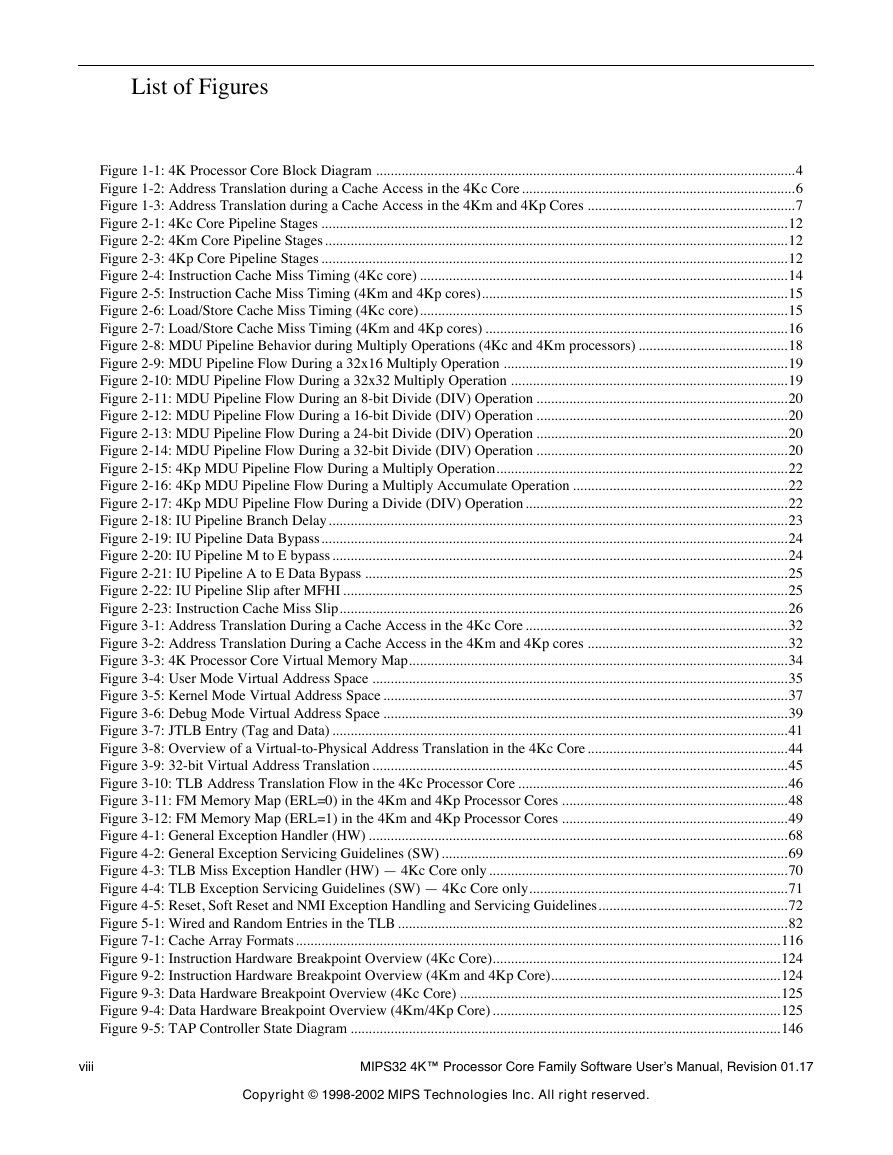
List of Figures Figure 1-1: 4K Processor Core Block Diagram ...................................................................................................................4 Figure 1-2: Address Translation during a Cache Access in the 4Kc Core ...........................................................................6 Figure 1-3: Address Translation during a Cache Access in the 4Km and 4Kp Cores .........................................................7 Figure 2-1: 4Kc Core Pipeline Stages ................................................................................................................................12 Figure 2-2: 4Km Core Pipeline Stages...............................................................................................................................12 Figure 2-3: 4Kp Core Pipeline Stages ................................................................................................................................12 Figure 2-4: Instruction Cache Miss Timing (4Kc core) .....................................................................................................14 Figure 2-5: Instruction Cache Miss Timing (4Km and 4Kp cores)....................................................................................15 Figure 2-6: Load/Store Cache Miss Timing (4Kc core).....................................................................................................15 Figure 2-7: Load/Store Cache Miss Timing (4Km and 4Kp cores) ...................................................................................16 Figure 2-8: MDU Pipeline Behavior during Multiply Operations (4Kc and 4Km processors) .........................................18 Figure 2-9: MDU Pipeline Flow During a 32x16 Multiply Operation ..............................................................................19 Figure 2-10: MDU Pipeline Flow During a 32x32 Multiply Operation ............................................................................19 Figure 2-11: MDU Pipeline Flow During an 8-bit Divide (DIV) Operation .....................................................................20 Figure 2-12: MDU Pipeline Flow During a 16-bit Divide (DIV) Operation .....................................................................20 Figure 2-13: MDU Pipeline Flow During a 24-bit Divide (DIV) Operation .....................................................................20 Figure 2-14: MDU Pipeline Flow During a 32-bit Divide (DIV) Operation .....................................................................20 Figure 2-15: 4Kp MDU Pipeline Flow During a Multiply Operation................................................................................22 Figure 2-16: 4Kp MDU Pipeline Flow During a Multiply Accumulate Operation ...........................................................22 Figure 2-17: 4Kp MDU Pipeline Flow During a Divide (DIV) Operation........................................................................22 Figure 2-18: IU Pipeline Branch Delay..............................................................................................................................23 Figure 2-19: IU Pipeline Data Bypass................................................................................................................................24 Figure 2-20: IU Pipeline M to E bypass.............................................................................................................................24 Figure 2-21: IU Pipeline A to E Data Bypass ....................................................................................................................25 Figure 2-22: IU Pipeline Slip after MFHI ..........................................................................................................................25 Figure 2-23: Instruction Cache Miss Slip...........................................................................................................................26 Figure 3-1: Address Translation During a Cache Access in the 4Kc Core ........................................................................32 Figure 3-2: Address Translation During a Cache Access in the 4Km and 4Kp cores .......................................................32 Figure 3-3: 4K Processor Core Virtual Memory Map........................................................................................................34 Figure 3-4: User Mode Virtual Address Space ..................................................................................................................35 Figure 3-5: Kernel Mode Virtual Address Space ...............................................................................................................37 Figure 3-6: Debug Mode Virtual Address Space ...............................................................................................................39 Figure 3-7: JTLB Entry (Tag and Data) .............................................................................................................................41 Figure 3-8: Overview of a Virtual-to-Physical Address Translation in the 4Kc Core .......................................................44 Figure 3-9: 32-bit Virtual Address Translation ..................................................................................................................45 Figure 3-10: TLB Address Translation Flow in the 4Kc Processor Core ..........................................................................46 Figure 3-11: FM Memory Map (ERL=0) in the 4Km and 4Kp Processor Cores ..............................................................48 Figure 3-12: FM Memory Map (ERL=1) in the 4Km and 4Kp Processor Cores ..............................................................49 Figure 4-1: General Exception Handler (HW) ...................................................................................................................68 Figure 4-2: General Exception Servicing Guidelines (SW) ...............................................................................................69 Figure 4-3: TLB Miss Exception Handler (HW) — 4Kc Core only..................................................................................70 Figure 4-4: TLB Exception Servicing Guidelines (SW) — 4Kc Core only.......................................................................71 Figure 4-5: Reset, Soft Reset and NMI Exception Handling and Servicing Guidelines....................................................72 Figure 5-1: Wired and Random Entries in the TLB ...........................................................................................................82 Figure 7-1: Cache Array Formats.....................................................................................................................................116 Figure 9-1: Instruction Hardware Breakpoint Overview (4Kc Core)...............................................................................124 Figure 9-2: Instruction Hardware Breakpoint Overview (4Km and 4Kp Core)...............................................................124 Figure 9-3: Data Hardware Breakpoint Overview (4Kc Core) ........................................................................................125 Figure 9-4: Data Hardware Breakpoint Overview (4Km/4Kp Core) ...............................................................................125 Figure 9-5: TAP Controller State Diagram ......................................................................................................................146 viii MIPS32 4K™ Processor Core Family Software User’s Manual, Revision 01.17 Copyright © 1998-2002 MIPS Technologies Inc. All right reserved.
分享到:
收藏