logo资料库

RTL8309N_Datasheet.pdf

第1页 / 共32页
第2页 / 共32页
第3页 / 共32页
第4页 / 共32页
第5页 / 共32页
第6页 / 共32页
第7页 / 共32页
第8页 / 共32页
资料共32页,剩余部分请下载后查看
1. General Description
2. Features
3. Block Diagram
4. Pin Assignments
4.1. Pin Assignments Diagram
4.2. Package Identification
4.3. Pin Assignments Table
4.4. Pin Descriptions
4.4.1. Media Connection Pins
4.4.2. Parallel LED Pins
4.4.3. Miscellaneous Interface Pins
4.4.4. Configuration Strapping Pins
4.4.5. Regulator Pins
4.4.6. Power and GND Pins
5. Physical Layer Function Description
5.1. MDI Interface
5.2. 10Base-T Transmit Function
5.3. 10Base-T Receive Function
5.4. 100Base-TX Transmit Function
5.5. 100Base-TX Receive Function
5.6. 100Base-FX Function
5.7. Auto-Negotiation for UTP Function
5.8. Crossover Detection and Auto Correction Function
5.9. Polarity Correction Function
5.10. IEEE 802.3az Energy Efficient Ethernet Function (EEE)
5.11. Link Down Power Saving Function
6. Switch Core Function Description
6.1. Hardware Reset and Software Reset Function
6.1.1. Hardware Reset
6.1.2. Software Reset
6.2. Layer 2 Learning and Forwarding Function
6.2.1. Forwarding
6.2.2. Learning
6.2.3. Address Table Aging
6.2.4. Layer 2 Multicast
6.3. MAC Limit Function
6.4. Reserved Multicast Address Handling Function
6.5. IEEE 802.3x Flow Control Function
6.6. Half Duplex Backpressure Function
6.6.1. Collision-Based Backpressure (Jam Mode)
6.6.2. Carrier-Based Backpressure (Defer Mode)
6.7. VLAN Function
6.7.1. Port-Based VLAN
6.7.2. IEEE 802.1Q Tagged-VID Based VLAN
6.7.3. Insert/Remove/Replace Tag
6.7.4. Ingress and Egress Rules
6.8. IEEE 802.1p Remarking Function
6.9. Bandwidth Control Function
6.9.1. Input Bandwidth Control
6.9.2. Output Bandwidth Control
6.10. Quality of Service (QoS) Function
6.10.1. Priority Arbitration
6.10.2. Port-Based Priority Assignment
6.10.3. IEEE 802.1Q-Based Priority Assignment
6.10.4. DSCP-Based Priority Assignment
6.10.5. IP Address-Based Priority
6.10.6. Internal Priority to Queue ID Table
6.10.7. Weighted Round-Robin
6.11. Layer2 Traffic Suppression Function (Storm Control)
6.12. Input & Output Drop Function
6.13. Loop Detection Function
6.14. Realtek Cable Tester Function
6.15. EEPROM Configuration Function
7. Interface Descriptions
7.1. I2C Master for EEPROM Auto-Download
7.2. SMI Interface for External CPU Access
8. LDO Regulator
9. Electrical Characteristics
9.1. Absolute Maximum Ratings
9.2. Recommended Operating Range
10. Mechanical Dimensions
10.1. Plastic Quad Flat No-Lead Package 64 Leads 9x9mm2 Outline
11. Ordering Information
SINGLE-CHIP 8-PORT 10/100MBPS ETHERNET SWITCH CONTROLLER DATASHEET Draft Rev. 1.0 10 January 2012 Track ID: RTL8309N 9-Port 10/100Mbps Ethernet Switch Controller i Track ID: Rev. 1.0
RTL8309N Datasheet COPYRIGHT ©2012 Realtek Semiconductor Corp. All rights reserved. No part of this document may be reproduced, transmitted, transcribed, stored in a retrieval system, or translated into any language in any form or by any means without the written permission of Realtek Semiconductor Corp. DISCLAIMER Realtek provides this document “as is”, without warranty of any kind, neither expressed nor implied, including, but not limited to, the particular purpose. Realtek may make improvements and/or changes in this document or in the product described in this document at any time. This document could include technical inaccuracies or typographical errors. TRADEMARKS Realtek is a trademark of Realtek Semiconductor Corporation. Other names mentioned in this document are trademarks/registered trademarks of their respective owners. CONFIDENTIALITY This document is confidential and should not be provided to a third-party without the permission of Realtek Semiconductor Corporation. USING THIS DOCUMENT This document is intended for the software engineer’s reference and provides detailed programming information. Though every effort has been made to ensure that this document is current and accurate, more information may have become available subsequent to the production of this guide. In that event, please contact your Realtek representative for additional information that may help in the development process. REVISION HISTORY Revision 1.0 Release Date 2012-1-10 Summary First release. 8-Port 10/100Mbps Ethernet Switch Controller ii Track ID: Rev. 1.0
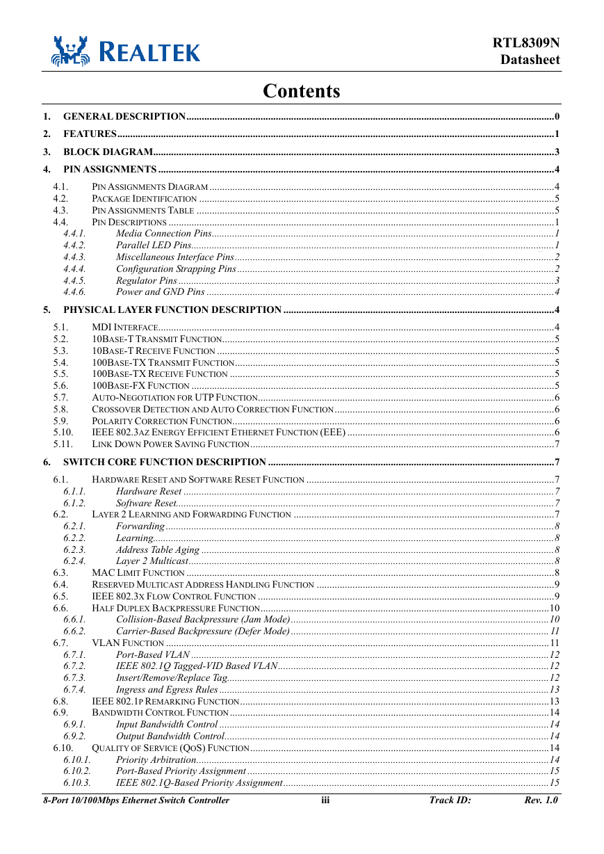
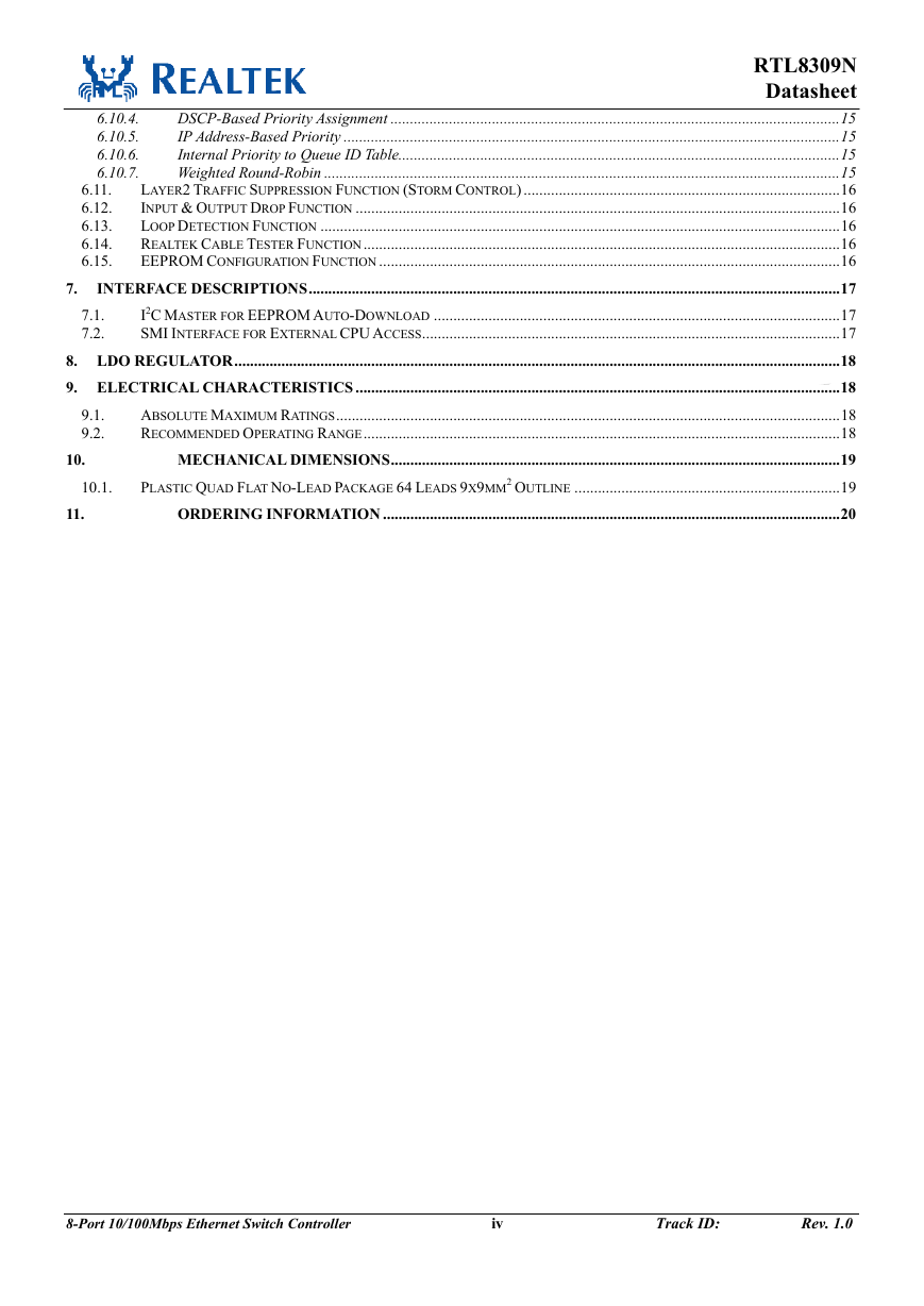
RTL8309N Datasheet Contents 4.1. 4.2. 4.3. 4.4. 6.1. 6.2. 4.4.1. 4.4.2. 4.4.3. 4.4.4. 4.4.5. 4.4.6. 5.1. 5.2. 5.3. 5.4. 5.5. 5.6. 5.7. 5.8. 5.9. 5.10. 5.11. 1. GENERAL DESCRIPTION................................................................................................................................................0 2. FEATURES...........................................................................................................................................................................1 3. BLOCK DIAGRAM.............................................................................................................................................................3 4. PIN ASSIGNMENTS ...........................................................................................................................................................4 PIN ASSIGNMENTS DIAGRAM .......................................................................................................................................4 PACKAGE IDENTIFICATION ...........................................................................................................................................5 PIN ASSIGNMENTS TABLE ............................................................................................................................................5 PIN DESCRIPTIONS .......................................................................................................................................................1 Media Connection Pins......................................................................................................................................1 Parallel LED Pins..............................................................................................................................................1 Miscellaneous Interface Pins.............................................................................................................................2 Configuration Strapping Pins............................................................................................................................2 Regulator Pins ...................................................................................................................................................3 Power and GND Pins ........................................................................................................................................4 5. PHYSICAL LAYER FUNCTION DESCRIPTION ..........................................................................................................4 MDI INTERFACE...........................................................................................................................................................4 10BASE-T TRANSMIT FUNCTION..................................................................................................................................5 10BASE-T RECEIVE FUNCTION ....................................................................................................................................5 100BASE-TX TRANSMIT FUNCTION.............................................................................................................................5 100BASE-TX RECEIVE FUNCTION ...............................................................................................................................5 100BASE-FX FUNCTION ..............................................................................................................................................5 AUTO-NEGOTIATION FOR UTP FUNCTION....................................................................................................................6 CROSSOVER DETECTION AND AUTO CORRECTION FUNCTION......................................................................................6 POLARITY CORRECTION FUNCTION..............................................................................................................................6 IEEE 802.3AZ ENERGY EFFICIENT ETHERNET FUNCTION (EEE) .................................................................................6 LINK DOWN POWER SAVING FUNCTION.......................................................................................................................7 6. SWITCH CORE FUNCTION DESCRIPTION ................................................................................................................7 HARDWARE RESET AND SOFTWARE RESET FUNCTION .................................................................................................7 Hardware Reset .................................................................................................................................................7 Software Reset....................................................................................................................................................7 LAYER 2 LEARNING AND FORWARDING FUNCTION ......................................................................................................7 Forwarding........................................................................................................................................................8 Learning.............................................................................................................................................................8 Address Table Aging ..........................................................................................................................................8 Layer 2 Multicast...............................................................................................................................................8 MAC LIMIT FUNCTION ................................................................................................................................................8 RESERVED MULTICAST ADDRESS HANDLING FUNCTION .............................................................................................9 IEEE 802.3X FLOW CONTROL FUNCTION ....................................................................................................................9 HALF DUPLEX BACKPRESSURE FUNCTION.................................................................................................................10 Collision-Based Backpressure (Jam Mode).....................................................................................................10 Carrier-Based Backpressure (Defer Mode).....................................................................................................11 VLAN FUNCTION ......................................................................................................................................................11 Port-Based VLAN ............................................................................................................................................12 IEEE 802.1Q Tagged-VID Based VLAN..........................................................................................................12 Insert/Remove/Replace Tag..............................................................................................................................12 Ingress and Egress Rules .................................................................................................................................13 IEEE 802.1P REMARKING FUNCTION.........................................................................................................................13 BANDWIDTH CONTROL FUNCTION.............................................................................................................................14 Input Bandwidth Control .................................................................................................................................14 Output Bandwidth Control...............................................................................................................................14 QUALITY OF SERVICE (QOS) FUNCTION.....................................................................................................................14 Priority Arbitration..........................................................................................................................................14 Port-Based Priority Assignment ......................................................................................................................15 IEEE 802.1Q-Based Priority Assignment........................................................................................................15 8-Port 10/100Mbps Ethernet Switch Controller iii Track ID: Rev. 1.0 6.6.1. 6.6.2. 6.7.1. 6.7.2. 6.7.3. 6.7.4. 6.1.1. 6.1.2. 6.2.1. 6.2.2. 6.2.3. 6.2.4. 6.10.1. 6.10.2. 6.10.3. 6.8. 6.9. 6.9.1. 6.9.2. 6.10. 6.3. 6.4. 6.5. 6.6. 6.7.
6.11. 6.12. 6.13. 6.14. 6.15. 6.10.4. 6.10.5. 6.10.6. 6.10.7. RTL8309N Datasheet DSCP-Based Priority Assignment ...................................................................................................................15 IP Address-Based Priority ...............................................................................................................................15 Internal Priority to Queue ID Table.................................................................................................................15 Weighted Round-Robin ....................................................................................................................................15 LAYER2 TRAFFIC SUPPRESSION FUNCTION (STORM CONTROL) .................................................................................16 INPUT & OUTPUT DROP FUNCTION ............................................................................................................................16 LOOP DETECTION FUNCTION .....................................................................................................................................16 REALTEK CABLE TESTER FUNCTION..........................................................................................................................16 EEPROM CONFIGURATION FUNCTION ......................................................................................................................16 INTERFACE DESCRIPTIONS........................................................................................................................................17 I2C MASTER FOR EEPROM AUTO-DOWNLOAD ........................................................................................................17 SMI INTERFACE FOR EXTERNAL CPU ACCESS...........................................................................................................17 8. LDO REGULATOR...........................................................................................................................................................18 9. ELECTRICAL CHARACTERISTICS ............................................................................................................................18 ABSOLUTE MAXIMUM RATINGS.................................................................................................................................18 RECOMMENDED OPERATING RANGE..........................................................................................................................18 MECHANICAL DIMENSIONS...................................................................................................................19 PLASTIC QUAD FLAT NO-LEAD PACKAGE 64 LEADS 9X9MM2 OUTLINE ....................................................................19 ORDERING INFORMATION .....................................................................................................................20 9.1. 9.2. 7. 7.1. 7.2. 10.1. 10. 11. 8-Port 10/100Mbps Ethernet Switch Controller iv Track ID: Rev. 1.0
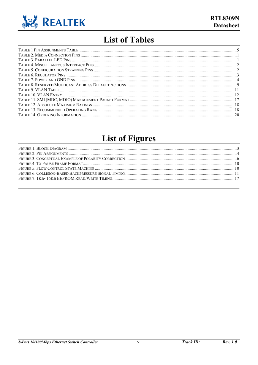
RTL8309N Datasheet List of Tables TABLE 1 PIN ASSIGNMENTS TABLE.................................................................................................................................................5 TABLE 2. MEDIA CONNECTION PINS ...............................................................................................................................................1 TABLE 3. PARALLEL LED PINS .......................................................................................................................................................1 TABLE 4. MISCELLANEOUS INTERFACE PINS...................................................................................................................................2 TABLE 5. CONFIGURATION STRAPPING PINS ...................................................................................................................................2 TABLE 6. REGULATOR PINS ............................................................................................................................................................3 TABLE 7. POWER AND GND PINS....................................................................................................................................................4 TABLE 8. RESERVED MULTICAST ADDRESS DEFAULT ACTIONS.....................................................................................................9 TABLE 9. VLAN TABLE................................................................................................................................................................11 TABLE 10. VLAN ENTRY .............................................................................................................................................................12 TABLE 11. SMI (MDC, MDIO) MANAGEMENT PACKET FORMAT................................................................................................17 TABLE 12. ABSOLUTE MAXIMUM RATINGS ..................................................................................................................................18 TABLE 13. RECOMMENDED OPERATING RANGE ...........................................................................................................................18 TABLE 14. ORDERING INFORMATION ............................................................................................................................................20 List of Figures FIGURE 1. BLOCK DIAGRAM ...........................................................................................................................................................3 FIGURE 2. PIN ASSIGNMENTS ..........................................................................................................................................................4 FIGURE 3. CONCEPTUAL EXAMPLE OF POLARITY CORRECTION......................................................................................................6 FIGURE 4. TX PAUSE FRAME FORMAT...........................................................................................................................................10 FIGURE 5. FLOW CONTROL STATE MACHINE................................................................................................................................10 FIGURE 6. COLLISION-BASED BACKPRESSURE SIGNAL TIMING ....................................................................................................11 FIGURE 7. 1KB~16KB EEPROM READ/WRITE TIMING................................................................................................................17 8-Port 10/100Mbps Ethernet Switch Controller v Track ID: Rev. 1.0
RTL8309N Datasheet 1. General Description The RTL8309N is an 8-port Fast Ethernet switch controller that integrates eight MACs, and eight physical layer transceivers for 10Base-T and 100Base-TX operation into a single chip. The RTL8309N contains a 2K-entry address lookup table. Two 4-way associative hash algorithms avoid hash collisions and maintain forwarding performance. Maximum packet length can be 2K bytes. Three types of independent storm filters are provided to filter packet storms, and an intelligent switch engine prevents Head-of-Line blocking problems. The RTL8309N supports 16 VLAN groups. These can be configured as port-based VLANs and/or 802.1Q tag-based VLANs. The RTL8309N also supports four Independent VLAN Learnings (IVLs). The RTL8309N supports several advanced QoS functions with four-level priority queues to improve multimedia or real-time networking applications, including: • Multi-priority assignment • Differential queue weight with WRR and SP packet scheduling • Port-based and queue-based rate limitation Energy-Efficient Ethernet (EEE) supports Low Power Idle Mode. When Low Power Idle Mode is enabled, systems on both sides of the link can disable portions of the functionality and save power during periods of low link utilization. The RTL8309N provides per-port one flexible LED functions for diagnostics, with five combination modes. A loop-detection function provides notification of network loops, the loop status can be notified by buzzer, LED or both. To simplify the peripheral power circuit, the RTL8309N integrated one LDO regulator to generate 1.0V from a 3.3V input power which needs only one external Diode. 8-Port 10/100Mbps Ethernet Switch Controller 0 Track ID: Rev. 1.0
2. Features Basic Switching Functions 8-port switch controller with transceiver for 10Base-T and 100Base-TX with: 8-port 10/100M UTP Non-blocking wire-speed reception and transmission and non-head-of-line-blocking forwarding Complies with IEEE 802.3/802.3u auto-negotiation Built-in high efficiency SRAM for packet buffer, with 2K-entry lookup table and two 4-way associative hash algorithms 2K byte maximum packet length Flow control fully supported: Half duplex: Back pressure flow control Full duplex: IEEE 802.3x flow control Service Quality Supports high performance QoS function on each port: Supports 4-level priority queues Weighted round robin service Supports strict priority Queue based bandwidth control 1Q-based, Port-based, DSCP-based, IP Input/Output port bandwidth control address-based, and other types of priority assignments Supports IEEE 802.1p Traffic Re-marking Security and Management Supports reserved control frame filtering RTL8309N Datasheet Supports advanced storm filtering Optional EEPROM interface for configuration VLAN Functions Supports up to 16 VLAN groups Flexible 802.1Q port/tag-based VLAN Supports four IVLs Leaky VLAN for unicast/multicast/broadcast/ARP packets Power Saving Functions Supports Energy-Efficient Ethernet (EEE) function (IEEE 802.3az) Link down Power Saving Mode Diagnostic Functions Supports hardware loop detection function, with LEDs to indicate the existence of a loop Supports cable diagnosis (RTCT function) LED indicators: Loop status indication RTCT status indication LEDs blink upon reset for LED diagnostics Other Features Optional MDI/MDIX auto crossover for plug-and-play Physical layer port Polarity Detection and Correction function 8-Port 10/100Mbps Ethernet Switch Controller 1 Track ID: Rev. 1.0
RTL8309N Datasheet Robust baseline wander correction for improved 100Base-TX performance Low power, 1.0/3.3V, 55nm CMOS technology 25MHz crystal 64-pin QFN package Integrated LDO regulator to generate 1.0V from 3.3V via one external Diode 8-Port 10/100Mbps Ethernet Switch Controller 2 Track ID: Rev. 1.0
分享到:
收藏