DESCRIPTION
The CM6642 is a low power single chip USB 2.0
High-Speed audio codec built-in MCU for flexible
applications. With integrated PWM LED driver and
3-channel ADC/ 2-channel DAC and S/PDIF
interface that makes it suitable for headset,
headphone, docking, speakers, and microphone
applications. The internal MCU can also be
developed to a lot of different applications, such
as VoIP device, Mobile Phone or Tablet/Slate
docking device. The CM6642 is compatible with
USB Audio Class 1.0/2.0 and USB 2.0 High-Speed,
thus it can plug & play without any additional
software installation on major operating systems.
The internal DAC support from 44.1~192 KHz and
ADC support from44.1~192 KHz sampling rate with
16/24 bits resolution.
The CM6642 also integrates 16K Byte OTP and is
crystal-less design, just requires few passive
components to make a finish product. Thus, it can
save the total BOM cost and PCB area can be
smaller.
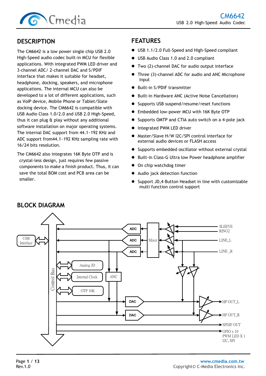
BLOCK DIAGRAM
USB
Interface
s
u
B
l
o
r
t
n
o
C
Analog JD
Internal Clock
ANC
OTP 16K
CM6642
USB 2.0 High-Speed Audio Codec
FEATURES
USB 1.1/2.0 Full-Speed and High-Speed compliant
USB Audio Class 1.0 and 2.0 compliant
Two (2)-channel DAC for audio output interface
Three (3)-channel ADC for audio and ANC Microphone
Input
Built-in S/PDIF transmitter
Built-in Hardware ANC (Active Noise Cancellation)
Supports USB suspend/resume/reset functions
Embedded low-power MCU with 16K Byte OTP
Supports OMTP and CTIA auto switch on a 4-pole jack
Integrated PWM LED driver
Master/Slave H/W I2C/SPI control interface for
external audio devices or FLASH access
Supports embedded oscillator without external crystal
Built-in Class-G Ultra low Power headphone amplifier
On chip watchdog timer
Audio jack detection function
Support JD,4-Button Headset in line with customizable
multi function control support
ADC
ADC
ADC
DAC
DAC
Mixer
SLEEVE
RING2
LINE_L
LINE _R
HP OUT_L
HP OUT_R
SPDIF OUT
GPIO x 10
PWM LED X 1
I2C, SPI
Page 1 / 13 www.cmedia.com.tw
Rev.1.0 Copyright© C-Media Electronics Inc.
�
Release Notes
Revision
0.9
0.91
0.92
1.0
Date
2016/10/05
2016/12/12
2017/02/16
2017/03/01
CM6642
USB 2.0 High-Speed Audio Codec
Description
First release.
ADC Sample rate support 192KHz
Modify Gain range
Formal release
Page 2 / 13 www.cmedia.com.tw
Rev.1.0 Copyright© C-Media Electronics Inc.
�
TABLE OF CONTENTS
CM6642
USB 2.0 High-Speed Audio Codec
Release Notes
TABLE OF CONTENTS
1 Description and Overview ...............................................................................
2
.................................................................................................. 2
........................................................................................... 3
4
Features.................................................................................................... 4
4
2.1
2.2
4
4
2.3
4
2.4
2.5
4
5
6
6
7
8
8
Absolute Maximum Ratings
Recommended Operation Condition ........................................................ 8
DC Characteristics ............................................................................. 8
SPDIF Output Timing .......................................................................... 8
I2C Control Interface .......................................................................... 9
Analog Performance .......................................................................... 10
11
USB Compliance................................................................................
Integrated Micro Controller Unit Microprocessor .........................................
Control Interface ..............................................................................
General..........................................................................................
Audio I/O........................................................................................
3 Applications ...............................................................................................
Pin Assignment ............................................................................................
4
4.1
CM6642 Pin-out Diagram (QFN48) ...........................................................
4.2
Pin Description .................................................................................
Electrical Characteristics
................................................................................
5.1
...................................................................
5.2
5.3
5.4
5.5
5.6
Package Dimension of CM6642
.........................................................................
5
6
Page 3 / 13 www.cmedia.com.tw
Rev.1.0 Copyright© C-Media Electronics Inc.
�
CM6642
USB 2.0 High-Speed Audio Codec
1 Description and Overview
The CM6642 is a low power single chip USB 2.0 High-Speed audio codec built-in MCU for flexible applications. With
integrated PWM LED driver and 3-channel ADC/ 2-channel DAC and S/PDIF interface that makes it suitable for
headset, headphone, docking, speakers, and microphone applications. The internal MCU can also be developed to a
lot of different applications, such as VoIP device, Mobile Phone or Tablet/Slate docking device. The CM6642 is
compatible with USB Audio Class 1.0/2.0 and USB 2.0 High-Speed, thus it can plug & play without any additional
software installation on major operating systems. The internal DAC support from 44.1~192 KHz and ADC support
from44.1~192 KHz sampling rate with 16/24 bits resolution.
The CM6642 also integrates 16K Byte OTP and crystal and just requires few passive components to make a finish
product. Thus, it can save the total BOM cost and PCB area can be smaller.
2 Features
2.1 USB Compliance
USB 1.1/2.0 Full-Speed and High-Speed compliant
USB Audio Class 1.0 and 2.0 compliant
USB Human Interface Device (HID) Class 1.1 compliant
Supports USB suspend/resume/reset functions
Support Selective Suspend mode
2.2
Integrated Micro Controller Unit Microprocessor
Embedded MCU micro-processor to handle the command/protocol transactions
Embedded 16K Byte OTP
4K Byte RAM for firmware extension and plug-in
HID interrupts/buttons/functions can be implemented via firmware codes
Provides maximum hardware configured flexibility with firmware code upgrade
VID/PID/Product String can program by firmware
2.3 Control Interface
12 GPIO pins and firmware programmable
GPIOs are configured as HID key and LED indicators
PWM LED Driver
2.4 General
Crystal-less (embedded crystal function)
Single 5V power supply (embedded 5V to 1.8V regulator for digital core, 5V to 1.8/3.3V regulator for digital IO, 5V
to 1.8V regulator for analog codec)
1.8/3.3V digital I/O pads with 5V tolerance
Industrial standard QFN-48 package (5x6.5mm)
2.5 Audio I/O
Playback Stream:
Page 4 / 13 www.cmedia.com.tw
Rev.1.0 Copyright© C-Media Electronics Inc.
�
CM6642
USB 2.0 High-Speed Audio Codec
Speaker/Headphone
Sample Rates: 44.1K/48K/96K/192KHz
Supports Bit Length: 16/24bits
DAC Gain Range is -65.6 ~ 0dB
S/PDIF transmitter
Sample Rates: 44.1K/48K/96K/192KHz
Supports Bit Length: 16/24 bits
Recording Stream:
Microphone
Sample Rates: 44.1K/48K/96K/192KHz
Supports Bit Length: 16/24 bits
ADC gain range is -33.5 ~ 30dB
A-A path Stream:
Line In to playback A-A path
Mix Line input to stereo playback both L/R channel
The Line In A-A path gain range is -34.5 ~ 12dB
**Note 1: A-A path means Analog to Analog Mixer path
3 Applications
USB/Type C Headset
USB/Type C Headphone
USB/Type C ANC Headphone/Headset
VoIP Headset
Tablet/Notebook/PCs Docking
Android Phone/Slate Docking
USB/Type C Speaker
USB/Type C Microphone
Page 5 / 13 www.cmedia.com.tw
Rev.1.0 Copyright© C-Media Electronics Inc.
�
4 Pin Assignment
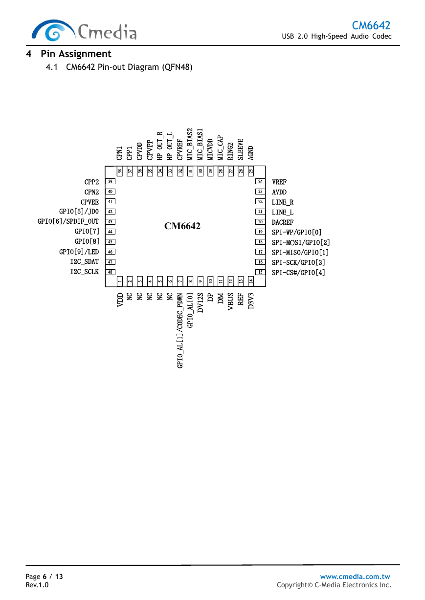
4.1 CM6642 Pin-out Diagram (QFN48)
CM6642
USB 2.0 High-Speed Audio Codec
CPP2
CPN2
CPVEE
GPIO[5]/JD0
GPIO[6]/SPDIF_OUT
GPIO[7]
GPIO[8]
GPIO[9]/LED
I2C_SDAT
I2C_SCLK
39
40
41
42
43
44
45
46
47
48
1
N
P
C
1
P
P
C
D
D
V
P
C
P
P
V
P
C
R
_
T
U
O
P
H
L
_
T
U
O
P
H
F
E
R
V
P
C
2
S
A
I
B
_
C
I
M
1
S
A
I
B
_
C
I
M
P
A
C
_
C
I
M
D
D
V
C
I
M
E
V
E
E
L
S
2
G
N
I
R
D
N
G
A
8
3
7
3
6
3
5
3
4
3
3
3
2
3
1
3
0
3
9
2
8
2
7
2
6
2
5
2
CM6642
1 2 3 4 5 6 7 8 9
0
1
1
1
2
1
3
1
4
1
C
N
C
N
C
N
C
N
C
N
D
D
V
S
2
1
V
D
P
D
M
D
S
U
B
V
F
E
R
3
V
3
D
]
0
[
L
A
_
O
I
P
G
N
W
D
P
_
C
E
D
O
C
/
]
1
[
L
A
_
O
I
P
G
24
23
22
21
20
19
18
17
16
15
VREF
AVDD
LINE_R
LINE_L
DACREF
SPI-WP/GPIO[0]
SPI-MOSI/GPIO[2]
SPI-MISO/GPIO[1]
SPI-SCK/GPIO[3]
SPI-CS#/GPIO[4]
Page 6 / 13 www.cmedia.com.tw
Rev.1.0 Copyright© C-Media Electronics Inc.
�
CM6642
USB 2.0 High-Speed Audio Codec
USB2.0 BUS Interface
Description
USB 2.0 data positive (USB D+ signal).
USB 2.0 data negative (USB D- signal).
External Reference. Requires 1% precision 6.25k/6.2k resistor to ground
Power/Ground
VDD for companion digital IO power
Regulated 1.2V output for core power
3.3V power output from integrated VBUS-to-3.3V regulator and I/O interface
USB bus 5.0V power input for integrated multiple regulators. This power pin can
accept 3.3V of USB power input for 3.3V system
Analog power
Charge Pump Positive Voltage Output
Charge Pump Voltage Input
Charge Pump Negative Voltage Output
Microphone bias power
Analog Ground.
Analog I/O reference voltage
Analog I/O reference voltage
DAC/ADC reference voltage
Charge pump Bucket Capacitor
Charge pump Bucket Capacitor
Charge pump Bucket Capacitor
Charge pump Bucket Capacitor
Analog Audio Interface
Line input left channel
Line input right channel
Combo jack microphone input
Combo jack microphone input
Headphone output Right channel
Headphone output Left channel
MIC BIAS Voltage output
MIC BIAS Voltage output
Microphone input reference voltage
GPIO/SPI/SPDIF Interface
General purpose input and output; operates even in USB suspend mode
General purpose input and output; operates even in USB suspend mode
SPI serial flash write protected/General purpose input and output
Serial data out from external flash/General purpose input and output
Serial data in to external flash/General purpose input and output
Clock signal to external flash/General purpose input and output
Chip select to external flash/General purpose input and output
Serial data receive/General purpose input and output/Jack detection
Serial data transmit/General purpose input and output/SPDIF-Out
General purpose input and output
General purpose input and output
General purpose input and output/LED controller
2-Wire Serial Bus (I2C)
I2C Bus Data Pin
I2C Bus Clock to Host
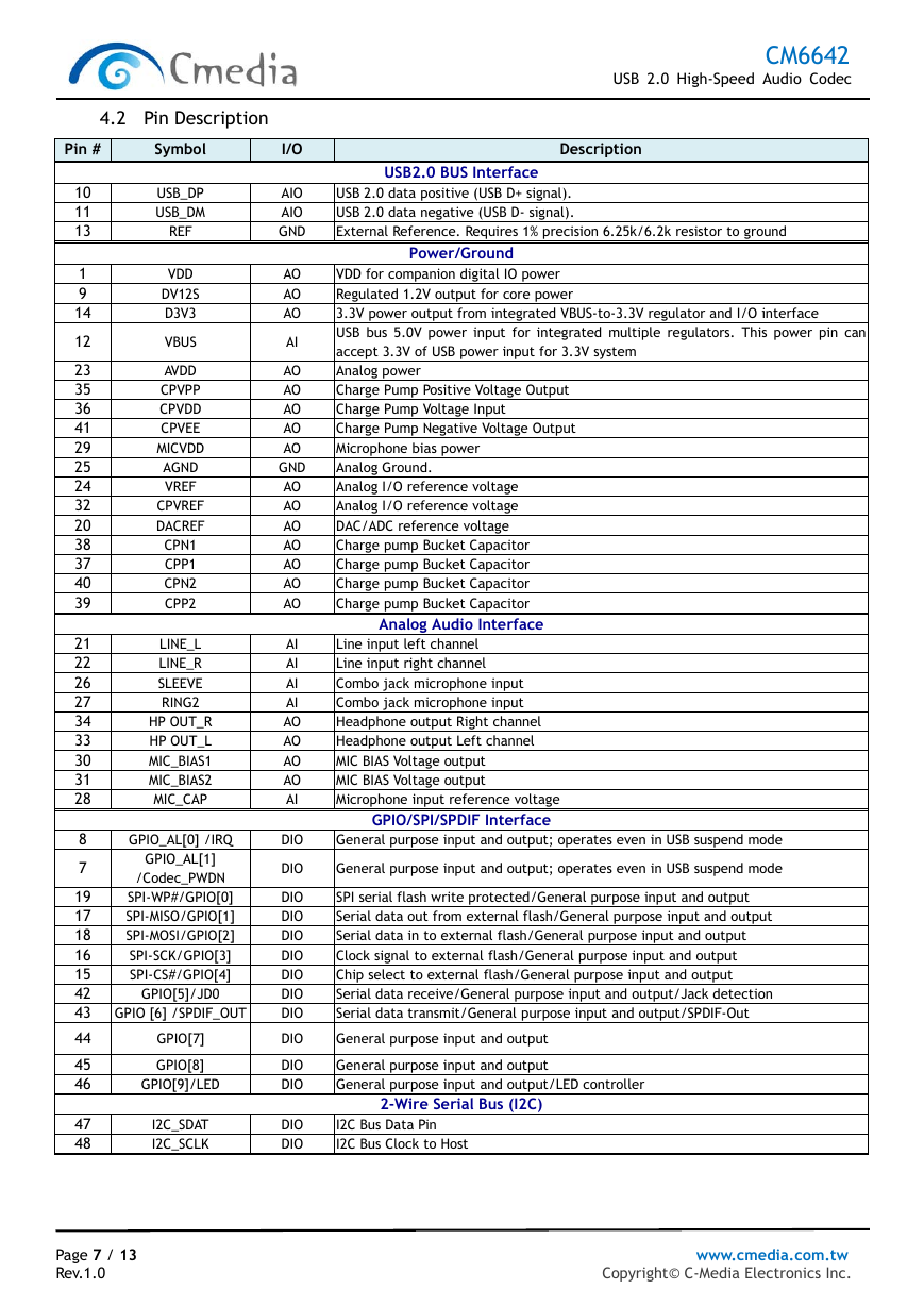
4.2 Pin Description
Pin #
Symbol
USB_DP
USB_DM
REF
VDD
DV12S
D3V3
VBUS
AVDD
CPVPP
CPVDD
CPVEE
MICVDD
AGND
VREF
CPVREF
DACREF
CPN1
CPP1
CPN2
CPP2
LINE_L
LINE_R
SLEEVE
RING2
HP OUT_R
HP OUT_L
MIC_BIAS1
MIC_BIAS2
MIC_CAP
GPIO_AL[0] /IRQ
GPIO_AL[1]
/Codec_PWDN
SPI-WP#/GPIO[0]
SPI-MISO/GPIO[1]
SPI-MOSI/GPIO[2]
SPI-SCK/GPIO[3]
SPI-CS#/GPIO[4]
GPIO[5]/JD0
GPIO [6] /SPDIF_OUT
GPIO[7]
GPIO[8]
GPIO[9]/LED
I2C_SDAT
I2C_SCLK
10
11
13
1
9
14
12
23
35
36
41
29
25
24
32
20
38
37
40
39
21
22
26
27
34
33
30
31
28
8
7
19
17
18
16
15
42
43
44
45
46
47
48
I/O
AIO
AIO
GND
AO
AO
AO
AI
AO
AO
AO
AO
AO
GND
AO
AO
AO
AO
AO
AO
AO
AI
AI
AI
AI
AO
AO
AO
AO
AI
DIO
DIO
DIO
DIO
DIO
DIO
DIO
DIO
DIO
DIO
DIO
DIO
DIO
DIO
Page 7 / 13 www.cmedia.com.tw
Rev.1.0 Copyright© C-Media Electronics Inc.
�
5 Electrical Characteristics
5.1 Absolute Maximum Ratings
CM6642
USB 2.0 High-Speed Audio Codec
Parameter
Power Supplies
Digital Power
Ambient Operating
Temperature
Storage Temperature
-
All Pins
Table. Absolute Maximum Ratings
Symbol
Minimum
Typical
Maximum
Units
VBus
Ta
Ts
-0.3
0
-40
5.0
-
-
5.5
+70
+125
V
oC
oC
ESD (Electrostatic Discharge)
Susceptibility Voltage
Pass 3500V
5.2 Recommended Operation Condition
Table. Operation Condition
Symbol
VBus
Description
Supply Voltage
Min.
4.75
Typ.
5
Max.
5.25
Unit
V
5.3 DC Characteristics
Table. DC Characteristics
Symbol
V
IH
V
IL
V
OH
V
OL
I
OH
I
OL
Description
Input Voltage High
Input Voltage Low
Output Voltage High
Output Voltage Low
Output Current High
Output Current Low
Min.
2
-0.5
2.4
-
-
-
Typ.
Max.
Unit
-
-
-
-
-
-
3.3
0.8
-
0.4
4
4
V
V
V
V
mA
mA
Units
MHz
ns
ns
ns (%)
ns (%)
5.4 SPDIF Output Timing
Table 1. SPDIF Output Timing
Parameter
Symbol
Minimum
Typical
Maximum
SPDIF-OUT Frequency
SPDIF-OUT Period
SPDIF-OUT Jitter
SPDIF-OUT High Level Width
SPDIF-OUT Low Level Width
-
Tcycle
Tjitter
THigh
TLow
-
-
-
3.072
325.6
-
-
-
4
156.2 (48%)
162.8 (50%)
169.2 (52%)
156.2 (48%)
162.8 (50%)
169.2 (52%)
Page 8 / 13 www.cmedia.com.tw
Rev.1.0 Copyright© C-Media Electronics Inc.
�



 2023年江西萍乡中考道德与法治真题及答案.doc
 2012年重庆南川中考生物真题及答案.doc
 2013年江西师范大学地理学综合及文艺理论基础考研真题.doc
 2020年四川甘孜小升初语文真题及答案I卷.doc
 2020年注册岩土工程师专业基础考试真题及答案.doc
 2023-2024学年福建省厦门市九年级上学期数学月考试题及答案.doc
 2021-2022学年辽宁省沈阳市大东区九年级上学期语文期末试题及答案.doc
 2022-2023学年北京东城区初三第一学期物理期末试卷及答案.doc
 2018上半年江西教师资格初中地理学科知识与教学能力真题及答案.doc
 2012年河北国家公务员申论考试真题及答案-省级.doc
 2020-2021学年江苏省扬州市江都区邵樊片九年级上学期数学第一次质量检测试题及答案.doc
 2022下半年黑龙江教师资格证中学综合素质真题及答案.doc