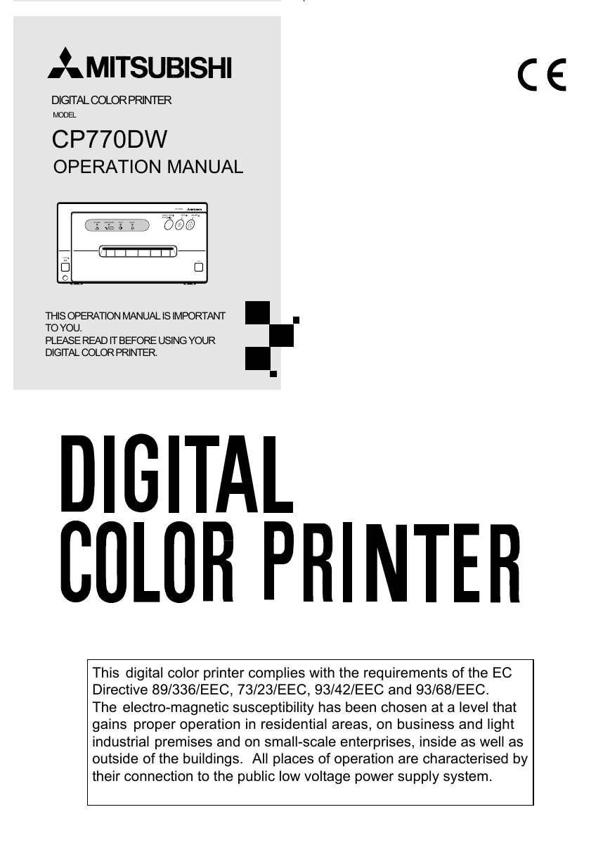
DIGITAL COLOR PRINTER
MODEL
CP770DW
OPERATION MANUAL
ALARM
SHEET/PAPER
SCSI
DATA
CP770DW
PAPER FEED
&CUT
COPY ONLINE
POWER
OPEN
THIS OPERATION MANUAL IS IMPORTANT
TO YOU.
PLEASE READ IT BEFORE USING YOUR
DIGITAL COLOR PRINTER.
This digital color printer complies with the requirements of the EC
Directive 89/336/EEC, 73/23/EEC, 93/42/EEC and 93/68/EEC.
The electro-magnetic susceptibility has been chosen at a level that
gains proper operation in residential areas, on business and light
industrial premises and on small-scale enterprises, inside as well as
outside of the buildings. All places of operation are characterised by
their connection to the public low voltage power supply system.
�
WARNING:
In the USA or Canada, use the AC power cord according to the recommendations as below, in order to comply with
UL2601-1 and CAN/CSA C22.2 No. 601.1.
Case 1. Connect to the 120V receptacle of the room or the host equipment.
The AC power cord should be UL or CSA approved and consist of type SJT, size 16 or 18AWG, length
2.5m or shorter cord with IEC320/C13 type, 125V 10A or higher rating connector and NEMA 5-15 type,
125V 10A or higher rating, Hospital Grade plug.
Case 2. Connect to the 230V receptacle of the room or the host equipment.
The AC power cord should be UL or CSA approved and consist of type SJT, size 16 or 18AWG, length
2.5m or shorter cord with IEC320/C13 type, 250V 10A or higher rating connector and NEMA 6-15 type,
250V 10A or higher rating, Hospital Grade plug.
Case 3. Connect to the 120V receptacle of the host equipment.
The AC power cord should be UL or CSA approved and consist of type SJT, size 16 or 18AWG, length
2.5m or shorter cord with IEC320/C13 type, 125V 10A or higher rating connector and IEC320-2.2/E type,
125V 10A or higher rating plug.
Case 4. Connect to the 230V receptacle of the host equipment.
The AC power cord should be UL or CSA approved and consist of type SJT, size 16 or 18AWG, length
2.5m or shorter cord with IEC320/C13 type, 250V 10A or higher rating connector and IEC320-2.2/E type,
250V 10A or higher rating plug.
CAUTION:
Changes or modifications not expressly approved by the party responsible for compliance could
void the user’s authority to operate the equipment.
NOTE:
This equipment has been tested and found to comply with the limits for a Class A digital device,
pursuant to Part 15 of the FCC Rules.
These limits are designed to provide reasonable protection against harmful interference when
the equipment is operated in a commercial environment. This equipment generates, uses, and
can radiate radio frequency energy and, if not installed and used in accordance with the instruc-
tion manual, may cause harmful interference to radio communications.
Operation of this equipment in a residential area is likely to cause harmful interference in which
case the user will be required to correct the interference at his or her own expense.
Information:
This class A digital apparatus complies with Canadian ICES-003.
"CLASSIFIED BY UNDERWRITERS LABORATORIES INC.®
WITH RESPECT TO ELECTRIC SHOCK, FIRE AND MECHANICAL HAZARDS ONLY IN AC-
CORDANCE WITH UL2601-1 AND CAN/CSA C22.2 No. 601.1"
�
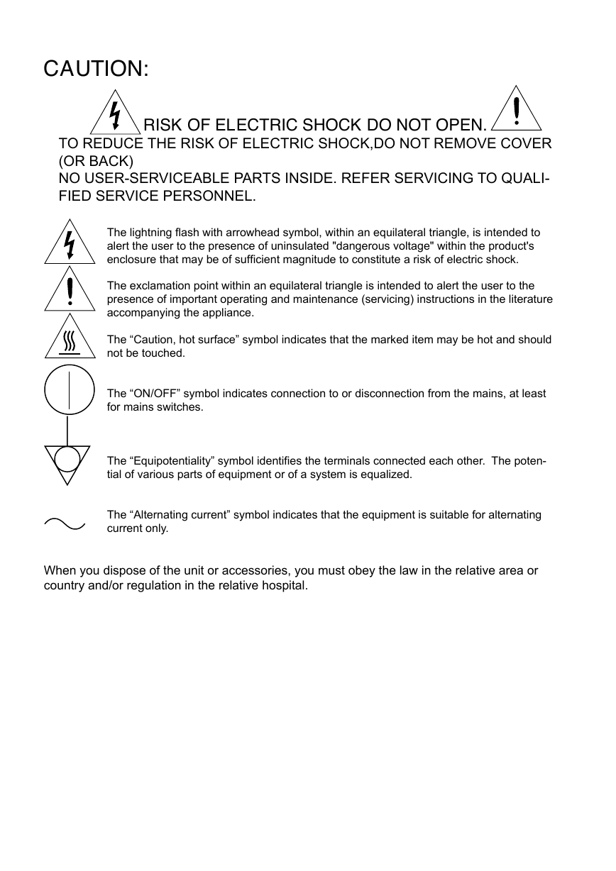
CAUTION:
RISK OF ELECTRIC SHOCK DO NOT OPEN.
TO REDUCE THE RISK OF ELECTRIC SHOCK,DO NOT REMOVE COVER
(OR BACK)
NO USER-SERVICEABLE PARTS INSIDE. REFER SERVICING TO QUALI-
FIED SERVICE PERSONNEL.
The lightning flash with arrowhead symbol, within an equilateral triangle, is intended to
alert the user to the presence of uninsulated "dangerous voltage" within the product's
enclosure that may be of sufficient magnitude to constitute a risk of electric shock.
The exclamation point within an equilateral triangle is intended to alert the user to the
presence of important operating and maintenance (servicing) instructions in the literature
accompanying the appliance.
The “Caution, hot surface” symbol indicates that the marked item may be hot and should
not be touched.
The “ON/OFF” symbol indicates connection to or disconnection from the mains, at least
for mains switches.
The “Equipotentiality” symbol identifies the terminals connected each other. The poten-
tial of various parts of equipment or of a system is equalized.
The “Alternating current” symbol indicates that the equipment is suitable for alternating
current only.
When you dispose of the unit or accessories, you must obey the law in the relative area or
country and/or regulation in the relative hospital.
�
WARNING:
Install and use this appliance in accordance with the operation manual for safety and EMC (Electromag-
netic Compatibility). If it is not installed and used in accordance with the operation manual, it may cause
interference to other equipment and/or other risk.
To prevent fire or shock hazard, do not expose this appliance to rain or moisture.
This appliance must be earthed.
In Europe, use the AC power cord according to the recommendations as below, in order to comply with
EN60601-1 and EN60950.
Connect to the 230V receptacle of the room or the host equipment.
The AC power cord should be VDE approved and consist of core size 1mm2 or bigger, length 2.5m or
shorter cord with IEC320/C13 type, 250V 10A or higher rating connector and CEE(7)VII type or IEC 320-
2.2/E type, 250V 10A or higher rating plug.
Use the parallel cable according to the recommendations as below, in order to comply with EN60601-1-2.
The parallel cable with appropriate plug should be 2 m long or shorter, comply with IEEE1284 standard,
shielded, 62Ω impedance, ELECOM Co. Ltd. printer cable No. CPC-D2 or equivalent one.
Use the SCSI cable according to the recommendations as below, in order to comply with EN60601-1-2.
The SCSI cable with appropriate plug should be 1 m long or shorter, comply with SCSI II standard,
Mitsubishi Electric Corporation JC-50V50V or equivalent one.
This product is to be employed with medical equipment, just for reference purpose, not for medical
diagnostic purpose.
�
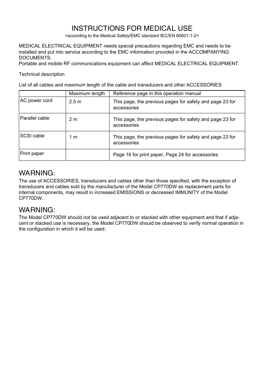
INSTRUCTIONS FOR MEDICAL USE
MEDICAL ELECTRICAL EQUIPMENT needs special precautions regarding EMC and needs to be
installed and put into service according to the EMC information provided in the ACCOMPANYING
DOCUMENTS.
Portable and mobile RF communications equipment can affect MEDICAL ELECTRICAL EQUIPMENT.
Technical description
List of all cables and maximum length of the cable and transducers and other ACCESSORIES
AC power cord
Parallel cable
SCSI cable
Print paper
Maximum length
2.5 m
Reference page in this operation manual
This page, the previous pages for safety and page 23 for
accessories
2 m
1 m
This page, the previous pages for safety and page 23 for
accessories
This page, the previous pages for safety and page 23 for
accessories
Page 16 for print paper, Page 24 for accessories
WARNING:
The use of ACCESSORIES, transducers and cables other than those specified, with the exception of
transducers and cables sold by the manufacturer of the Model CP770DW as replacement parts for
internal components, may result in increased EMISSIONS or decreased IMMUNITY of the Model
CP770DW.
WARNING:
The Model CP770DW should not be used adjacent to or stacked with other equipment and that if adja-
cent or stacked use is necessary, the Model CP770DW should be observed to verify normal operation in
the configuration in which it will be used.
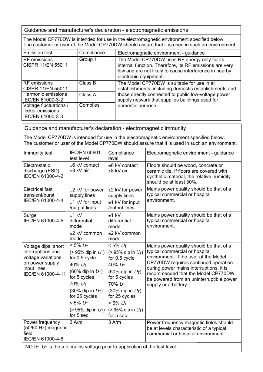
�Guidance and manufacturer's declaration - electromagnetic emissions
The Model CP770DW is intended for use in the electromagnetic environment specified below.
The customer or user of the Model CP770DW should assure that it is used in such an environment.
Emission test
RF emissions
CISPR 11/EN 55011
Compliance
Group 1
Electromagnetic environment - guidance
The Model CP770DW uses RF energy only for its
internal function. Therefore, its RF emissions are very
low and are not likely to cause interference in nearby
electronic equipment.
The Model CP770DW is suitable for use in all
establishments, including domestic establishments and
those directly connected to public low-voltage power
supply network that supplies buildings used for
domestic purpose.
RF emissions
CISPR 11/EN 55011
Harmonic emissions
IEC/EN 61000-3-2
Voltage fluctuations /
flicker emissions
IEC/EN 61000-3-3
Class B
Class A
Complies
Guidance and manufacturer's declaration - electromagnetic immunity
The Model CP770DW is intended for use in the electromagnetic environment specified below.
The customer or user of the Model CP770DW should assure that it is used in such an environment.
Immunity test
Electromagnetic environment - guidance
Floors should be wood, concrete or
ceramic tile. If floors are covered with
synthetic material, the relative humidity
should be at least 30%.
Mains power quality should be that of a
typical commercial or hospital
environment.
Mains power quality should be that of a
typical commercial or hospital
environment.
Mains power quality should be that of a
typical commercial or hospital
environment. If the user of the Model
CP770DW requires continued operation
during power mains interruptions, it is
recommended that the Model CP770DW
be powered from an uninterruptible power
supply or a battery.
Electrostatic
discharge (ESD)
IEC/EN 61000-4-2
Electrical fast
transient/burst
IEC/EN 61000-4-4
Surge
IEC/EN 61000-4-5
Voltage dips, short
interruptions and
voltage variations
on power supply
input lines
IEC/EN 61000-4-11
IEC/EN 60601
test level
±6 kV contact
±8 kV air
Compliance
level
±6 kV contact
±8 kV air
±2 kV for power
supply lines
±1 kV for input
/output lines
±1 kV
differential
mode
±2 kV common
mode
< 5% UT
(> 95% dip in UT)
for 0.5 cycle
40% UT
(60% dip in UT)
for 5 cycles
70% UT
(30% dip in UT)
for 25 cycles
< 5% UT
(> 95% dip in UT)
for 5 sec.
3 A/m
±2 kV for power
supply lines
±1 kV for input
/output lines
±1 kV
differential
mode
±2 kV common
mode
< 5% UT
(> 95% dip in UT)
for 0.5 cycle
40% UT
(60% dip in UT)
for 5 cycles
70% UT
(30% dip in UT)
for 25 cycles
< 5% UT
(> 95% dip in UT)
for 5 sec.
3 A/m
Power frequency
(50/60 Hz) magnetic
field
IEC/EN 61000-4-8
NOTE UT is the a.c. mains voltage prior to application of the test level.
Power frequency magnetic fields should
be at levels characteristic of a typical
commercial or hospital environment.
�
Guidance and manufacturer's declaration - electromagnetic immunity
The Model CP770DW is intended for use in the electromagnetic environment specified below.
The customer or user of the Model CP770DW should assure that it is used in such an environment.
Immunity test
IEC/EN 60601
test level
Compliance
level
Conducted RF
IEC/EN 61000-4-6
Radiated RF
IEC/EN 61000-4-3
3 Vrms
150 kHz to 80
MHz
3 V/m
80 MHz to 2.5
GHz
3 Vrms
3 V/m
Electromagnetic environment - guidance
Portable and mobile RF communications
equipment should be used no closer to
any part of the Model CP770DW,
including cables, than the recommended
separation distance calculated from the
equation applicable to frequency of the
transmitter.
Recommended separation distance
d=1.2√P
d=1.2√P 80 MHz to 800 MHz
d=2.3√P 800 MHz to 2.5 GHz
where P is the maximum output power
rating of the transmitter in watts (W)
according to the transmitter manufacturer
and d is the recommended separation
distance in meters (m).
Field strengths from fixed RF transmitters,
as determined by an electromagnetic site
survey,a should be less than the
compliance level in each frequency
range.b
Interference may occur in the vicinity of
equipment marked with the following
symbol:
NOTE1. At 80 MHz and 800 MHz, the higher frequency range applies.
NOTE2. These guidelines may not apply in all situations. Electromagnetic propagation is affected
by absorption and reflection from structures, objects and people.
a
Field strengths from fixed transmitters, such as base stations for radio (cellular/cordless)
telephones and land mobile radios, amateur radio, AM and FM radio broadcast and TV
broadcast cannot be predicted theoretically with accuracy. To assess the electromagnetic
environment due to fixed RF transmitters, an electromagnetic site survey should be
considered. If the measured field strength in the location in which the Model CP770DW is
used exceeds the applicable RF compliance level above, the Model CP770DW should be
observed to verify normal operation. If abnormal performance is observed, additional
measures may be necessary, such as reorienting or relocating the Model CP770DW.
b Over the frequency range 150 kHz to 80 MHz, field strength should be less than 3 V/m.
�
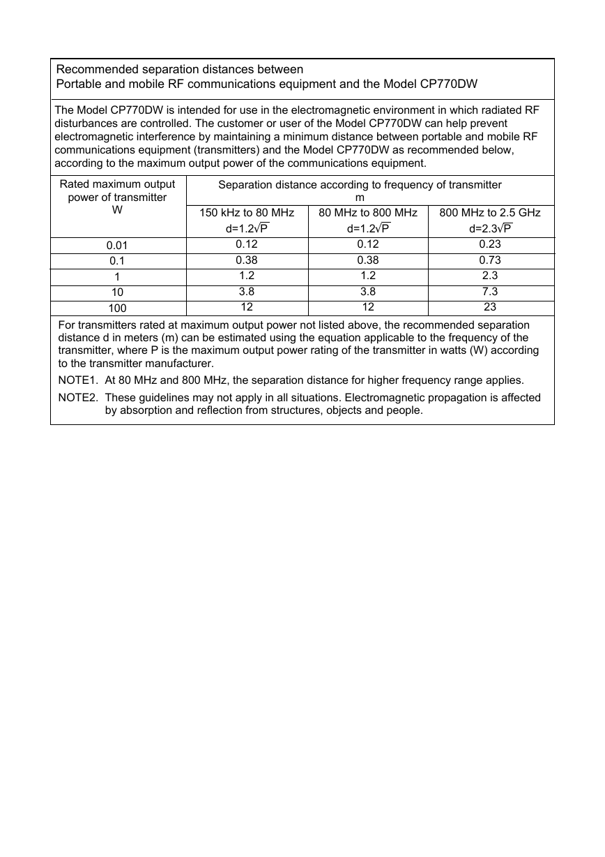
Recommended separation distances between
Portable and mobile RF communications equipment and the Model CP770DW
The Model CP770DW is intended for use in the electromagnetic environment in which radiated RF
disturbances are controlled. The customer or user of the Model CP770DW can help prevent
electromagnetic interference by maintaining a minimum distance between portable and mobile RF
communications equipment (transmitters) and the Model CP770DW as recommended below,
according to the maximum output power of the communications equipment.
Rated maximum output
Separation distance according to frequency of transmitter
power of transmitter
m
W
0.01
0.1
1
10
100
150 kHz to 80 MHz
d=1.2√P
80 MHz to 800 MHz
d=1.2√P
800 MHz to 2.5 GHz
d=2.3√P
0.12
0.38
1.2
3.8
12
0.12
0.38
1.2
3.8
12
0.23
0.73
2.3
7.3
23
For transmitters rated at maximum output power not listed above, the recommended separation
distance d in meters (m) can be estimated using the equation applicable to the frequency of the
transmitter, where P is the maximum output power rating of the transmitter in watts (W) according
to the transmitter manufacturer.
NOTE1. At 80 MHz and 800 MHz, the separation distance for higher frequency range applies.
NOTE2. These guidelines may not apply in all situations. Electromagnetic propagation is affected
by absorption and reflection from structures, objects and people.
�




 2023年江西萍乡中考道德与法治真题及答案.doc
 2012年重庆南川中考生物真题及答案.doc
 2013年江西师范大学地理学综合及文艺理论基础考研真题.doc
 2020年四川甘孜小升初语文真题及答案I卷.doc
 2020年注册岩土工程师专业基础考试真题及答案.doc
 2023-2024学年福建省厦门市九年级上学期数学月考试题及答案.doc
 2021-2022学年辽宁省沈阳市大东区九年级上学期语文期末试题及答案.doc
 2022-2023学年北京东城区初三第一学期物理期末试卷及答案.doc
 2018上半年江西教师资格初中地理学科知识与教学能力真题及答案.doc
 2012年河北国家公务员申论考试真题及答案-省级.doc
 2020-2021学年江苏省扬州市江都区邵樊片九年级上学期数学第一次质量检测试题及答案.doc
 2022下半年黑龙江教师资格证中学综合素质真题及答案.doc