IEEE SIGNAL PROCESSING LETTERS, VOL. 20, NO. 1, JANUARY 2013
51
Joint Clock Synchronization and Ranging:
Asymmetrical Time-Stamping and Passive Listening
Sundeep Prabhakar Chepuri, Student Member, IEEE, Raj Thilak Rajan, Student Member, IEEE,
Geert Leus, Fellow, IEEE, and Alle-Jan van der Veen, Fellow, IEEE
Abstract—A fully asynchronous network with one sensor and
anchors (nodes with known locations) is considered in this
letter. We propose a novel asymmetrical time-stamping and
passive listening (ATPL) protocol for joint clock synchronization
and ranging. The ATPL protocol exploits broadcast to not only
reduce the number of active transmissions between the nodes, but
also to obtain more information. This is used in a simple estimator
based on least-squares (LS) to jointly estimate all the unknown
clock-skews, clock-offsets, and pairwise distances of the sensor to
each anchor. The Cramér–Rao lower bound (CRLB) is derived
for the considered problem. The proposed estimator is shown to
be asymptotically efficient, meets the CRLB, and also performs
better than the available clock synchronization algorithms.
Index Terms—Clock synchronization, clock-offset, clock-skew,
wireless sensor networks.
I. INTRODUCTION
C LOCK synchronization among different nodes each
having its own autonomous clock is a key component
of a wireless sensor network (WSN). A WSN enables coordi-
nated functions such as data sampling, data fusion, time-based
channel sharing and scheduling, sleep and wake-up coordi-
nation, and other time-based tasks [1]. These tasks demand a
common time frame for the entire network. Individual clocks
in a WSN drift from each other due to imperfections in the
oscillator, aging and other environmental variations, and it is
essential to determine these drifts. Sensor nodes are usually
powered with just a battery. Thus, all the tasks of a WSN,
including synchronization, should be carefully performed to
ensure longer operating lifetime. For synchronization,
this
means to minimize the number of transmissions between nodes
during which the time-stamps are recorded.
Early research on synchronization focussed on protocol de-
sign [1], e.g., hierarchical protocols like the network time pro-
tocol (NTP), which can be used for applications where the re-
Manuscript received August 02, 2012; revised September 21, 2012; ac-
cepted September 21, 2012. Date of publication October 03, 2012; date of
current version November 28, 2012. This work was supported in part by
STW under FASTCOM project (10551) and OLFAR project (10556), and in
part by NWO-STW under the VICI program (10382). The associate editor
coordinating the review of this manuscript and approving it for publication was
Prof. Chandra Ramabhadra Murthy.
S. P. Chepuri, G. Leus, and A.-J. van der Veen are with the Faculty of
Electrical Engineering, Mathematics and Computer Science, Delft Univer-
sity of Technology, Delft, The Netherlands (e-mail: s.p.chepuri@tudelft.nl;
g.j.t.leus@tudelft.nl;a.j.vanderveen@tudelft.nl.
R. T. Rajan is with the Faculty of Electrical Engineering, Mathematics and
Computer Science, Delft University of Technology, The Netherlands, and also
with Netherlands Institute for Radio Astronomy (ASTRON), Dwingeloo, The
Netherlands. (e-mail: rajan@astron.nl).
Color versions of one or more of the figures in this paper are available online
at http://ieeexplore.ieee.org.
Digital Object Identifier 10.1109/LSP.2012.2222371
quirements on the synchronization accuracies are not too strin-
gent. For better synchronization (below the order of a
), a
plethora of algorithms based on the exchange of time-stamps
has been proposed [1]–[4], which could operate via two-way
time-stamp exchange [2] or pairwise broadcast synchronization
(PBS) [3]. In a WSN, assuming one of the nodes as a reference,
the unknown clock-skew and clock-offset of the other nodes
could be estimated using a pairwise least-squares (PLS) esti-
mator [4]. Extending from a pair of nodes to a network, a global
least-squares (GLS) estimator based on the two-way time-stamp
exchange was also proposed in [4], for joint synchronization and
ranging. The GLS algorithm exploits the redundancy achieved
due to all possible pairwise links in the network.
In this letter, we propose a novel scheme for joint clock syn-
chronization and ranging in energy-efficient WSNs, in which we
harness the broadcast property of the wireless medium to signif-
icantly reduce the number of active transmissions between the
nodes and at the same time we aim to increase both the synchro-
nization and ranging accuracies.
More specifically, we propose an asymmetrical
time-
stamping and passive listening (ATPL) protocol for joint clock
synchronization and ranging. The ATPL protocol presumes the
protocol proposed in [5] and [3]. The main goal of [3] was
synchronization and did not focus on ranging. The algorithm
proposed in [5] also exploits the broadcast property and fo-
cussed on localization of a target node in an asynchronous
network, however, estimation of the clock parameters was not
specifically considered. In the ATPL protocol, during commu-
nication between a pair of nodes, time-stamps are recorded and
exchanged. Besides this, the remaining nodes in the network
also passively listen and record the time-stamps with their
respective clocks, in a cooperative way. However, they do not
respond back to either of the active node pair. In addition,
the protocol does not put any constraint on the sequence of
transmissions, and this together with passive listening results
in asymmetrical links, and hence, asymmetrical time-stamps.
The ATPL protocol is energy-efficient in the sense that we
obtain more information just by passive listening, and reception
usually consumes less power than transmission.
For a fully asynchronous network with one sensor and
an-
chors, we propose a novel estimator based on the ATPL protocol
for jointly estimating all the unknown clock-skews, clock-off-
sets, and pairwise distances of the sensor to each anchor, which
is the main contribution of this work.
Notation
denotes transposition;
Upper (lower) bold face letters are used for matrices (column
(
) denotes the element-
vectors);
denotes the ele-
wise matrix or vector product (division);
a block diagonal
ment-wise matrix or vector squaring;
matrix with the matrices in its argument on the main diagonal;
1070-9908/$31.00 © 2012 IEEE
�
52
IEEE SIGNAL PROCESSING LETTERS, VOL. 20, NO. 1, JANUARY 2013
(
) denotes the
;
tity matrix of size
is the Kronecker product.
1 vector of ones (zeros);
denotes the expectation operation;
is an iden-
II. SYSTEM MODEL
We consider a fully asynchronous network with
anchors
and one sensor (node 0). We assume that one of the nodes has
a relatively stable clock oscillator and is used as a clock refer-
ence. All the other nodes suffer from clock-skews and clock-off-
sets. The network model considered here is a special case of the
model in [4], as the pairwise distances of certain nodes (anchors)
are now assumed to be known.
The distance between the th and the th node is denoted by
. The distance between the sensor and the th anchor
be the local
is denoted by
time at the th node and be the reference time. We assume that
the relation between the local time and the reference time can
be given by a first order affine clock model [4],
, and is unknown. Let
(1)
and
where
is the clock-skew,
is the clock-offset,
are the synchronization param-
eters of the th node. Without loss of generality, we use an-
.
chor
The unknown synchronization parameters are collected in
as absolute time reference, i.e.,
. The un-
known clock-skews and clock-offsets are respectively given by
(2)
and
The transmission and reception time-stamps are recorded
both during the forward link ( th active anchor to the sensor)
and the reverse link (sensor to the th active anchor). The
time-stamp recorded at the th node when the
th iteration
, and on arrival of the
message departs is denoted by
corresponding message, the th node records the time-stamp
. Note that the time-stamps recorded at the sensor will be
either
or
.
III. THE ATPL PROTOCOL
In the two-way time-stamp exchange protocol between the
th anchor and the sensor, the remaining nodes of the network
are idle. In the ATPL protocol, we propose that all the remaining
anchors passively listen to the communication between
the th anchor and the sensor, and record the time-stamps
of their respective local clocks. By doing so, we obtain
more information with extra equations corresponding to trans-
missions between a) active anchor and other passive anchors,
and b) sensor and remaining passive anchors. This is additional
to the equations corresponding to the active anchor sensor pair
as compared to the two-way time-stamp exchange. The ATPL
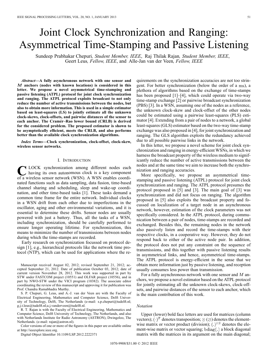
protocol initiated by the th anchor is illustrated in Fig. 1. An
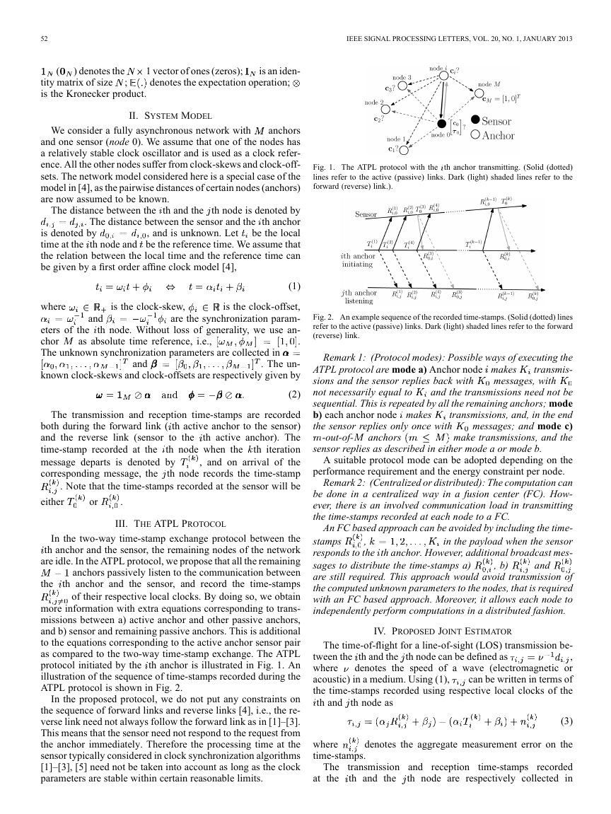
illustration of the sequence of time-stamps recorded during the
ATPL protocol is shown in Fig. 2.
In the proposed protocol, we do not put any constraints on
the sequence of forward links and reverse links [4], i.e., the re-
verse link need not always follow the forward link as in [1]–[3].
This means that the sensor need not respond to the request from
the anchor immediately. Therefore the processing time at the
sensor typically considered in clock synchronization algorithms
[1]–[3], [5] need not be taken into account as long as the clock
parameters are stable within certain reasonable limits.
Fig. 1. The ATPL protocol with the th anchor transmitting. (Solid (dotted)
lines refer to the active (passive) links. Dark (light) shaded lines refer to the
forward (reverse) link.).
Fig. 2. An example sequence of the recorded time-stamps. (Solid (dotted) lines
refer to the active (passive) links. Dark (light) shaded lines refer to the forward
(reverse) link.
Remark 1: (Protocol modes): Possible ways of executing the
transmis-
ATPL protocol are mode a) Anchor node makes
sions and the sensor replies back with
not necessarily equal to
and the transmissions need not be
sequential. This is repeated by all the remaining anchors; mode
b) each anchor node makes
transmissions, and, in the end
messages; and mode c)
the sensor replies only once with
make transmissions, and the
messages, with
anchors
-out-of-
sensor replies as described in either mode a or mode b.
A suitable protocol mode can be adopted depending on the
performance requirement and the energy constraint per node.
Remark 2: (Centralized or distributed): The computation can
be done in a centralized way in a fusion center (FC). How-
ever, there is an involved communication load in transmitting
the time-stamps recorded at each node to a FC.
An FC based approach can be avoided by including the time-
in the payload when the sensor
stamps
responds to the th anchor. However, additional broadcast mes-
sages to distribute the time-stamps a)
are still required. This approach would avoid transmission of
the computed unknown parameters to the nodes, that is required
with an FC based approach. Moreover, it allows each node to
independently perform computations in a distributed fashion.
and
, b)
,
IV. PROPOSED JOINT ESTIMATOR
The time-of-flight for a line-of-sight (LOS) transmission be-
tween the th and the th node can be defined as
,
where
denotes the speed of a wave (electromagnetic or
can be written in terms of
acoustic) in a medium. Using (1),
the time-stamps recorded using respective local clocks of the
th and th node as
(3)
where
time-stamps.
denotes the aggregate measurement error on the
The transmission and reception time-stamps
the
recorded
th node are respectively collected in
th and the
at
�
CHEPURI et al.: JOINT CLOCK SYNCHRONIZATION AND RANGING
vectors
, where
and
is
the number of transmissions made by the th node. The error
.
vector is denoted by
For the sake of exposition, we consider a network with one
anchors (node 1 and node 2) and
transmis-
sensor (node 0) and
the following example protocol: (i) node 1 makes
sions, node 0 and node 2 passively listen, (ii) node 2 makes
transmissions, node 0 and node 1 passively listen, and finally
messages and node 1 and
(iii) sensor node 0 responds with
node 2 passively listen. This is an example of protocol mode b
that was described earlier.
Collecting the clock parameters of the th node in a vector
, we can now write the equations of the form
time-stamps
given in (3), obtained for all the
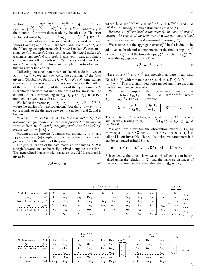
recorded in a matrix-vector form as shown in (4) at the bottom
of the page. The ordering of the rows of the system matrix
is arbitrary and does not imply the order of transmission. The
have two
columns of
non-zero sub-vectors each as
corresponding to
, and
,
.
We define the vector
where the entries of
corresponds to the distance between the nodes 1 and 2, and is
known.
are not known. Note that
Remark 3: (Rank-deficiency): The linear model in (4) does
not have a unique solution, unless we impose certain linear con-
straints. Here, we do that by assigning node 2 as the clock-ref-
erence, i.e.,
and
Moving all the knowns (columns corresponding to
) to one side, (4) simplifies to the generalized linear model
.
given in (5) at the bottom of the page.
The generalization of the data model (5) for any
is
straightforward and can be easily derived along the same lines.
The generalized linear model based on the ATPL protocol is
given by
,
(6)
53
and
where
,
,
, all having a similar structure as that of (5).
Remark 4:
(Correlated error vector): In case of broad-
are not uncorrelated
casting, the entries of the error vector
due to a common error on the transmit time-stamp
.
We assume that the aggregate error
in (3) is due to the
additive stochastic noise components on the time-stamps,
denoted by
model the aggregate error in (3) as
and the time-stamps,
denoted by
. We
(7)
and
where both
Gaussian [6] with variance
for
models could be considered.)
are modeled as zero mean i.i.d.
, such that,
. (This is a simplified noise model and more accurate
We
can
compute
the
covariance matrix
. For
, we find
as
, where
(8)
in a
The structure of
similar way, leading to
can be generalized for any
.
We can now prewhiten the observation model in (5) by
is
forming
tall and is left-invertible. Hence, the unknown parameters in
can be estimated using LS, i.e.,
. For
and
,
can be ob-
Subsequently, the clock-skews
tained using the relation in (2), and the pairwise distances of
the sensor to each anchor using the relation
, clock-offsets
.
(9)
(4)
(5)
�
54
IEEE SIGNAL PROCESSING LETTERS, VOL. 20, NO. 1, JANUARY 2013
zero-mean Gaussian, then
, where
matrix is given by [4]
can be computed as
is a Jacobian matrix. The Jacobian
(10)
with sub-blocks
where
,
columns of
, and
corresponding to ,
are selection matrices to select the
, and
, respectively.
VI. SIMULATIONS
[6].
and
and clock-offsets
A network with one sensor and 10 anchors is considered
for simulations. Both the sensor and the anchor nodes are
deployed randomly within a range of 100 m. Clock-skews
are uniformly distributed in the range
, respectively. We
use an observation interval of 100 s during which the clock-pa-
. The time-stamps
rameters are fixed and
are corrupted with an i.i.d. Gaussian process having a standard
deviation
The proposed estimator based on the ATPL protocol is com-
pared with the GLS algorithm proposed in [4, Fig. 3(c)], as
it is already shown to outperform other existing synchroniza-
tion algorithms. We apply the GLS algorithm based on two-way
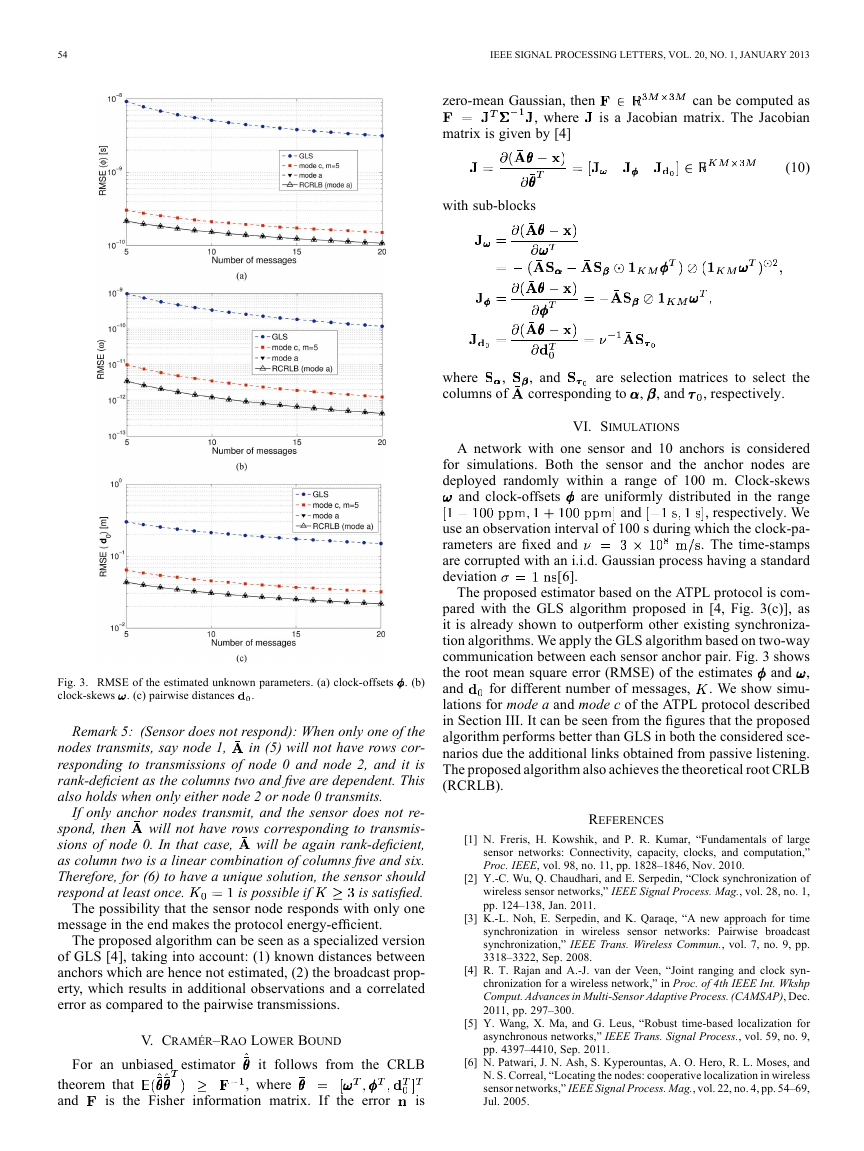
communication between each sensor anchor pair. Fig. 3 shows
,
the root mean square error (RMSE) of the estimates
. We show simu-
and
lations for mode a and mode c of the ATPL protocol described
in Section III. It can be seen from the figures that the proposed
algorithm performs better than GLS in both the considered sce-
narios due the additional links obtained from passive listening.
The proposed algorithm also achieves the theoretical root CRLB
(RCRLB).
for different number of messages,
and
REFERENCES
[1] N. Freris, H. Kowshik, and P. R. Kumar, “Fundamentals of large
sensor networks: Connectivity, capacity, clocks, and computation,”
Proc. IEEE, vol. 98, no. 11, pp. 1828–1846, Nov. 2010.
[2] Y.-C. Wu, Q. Chaudhari, and E. Serpedin, “Clock synchronization of
wireless sensor networks,” IEEE Signal Process. Mag., vol. 28, no. 1,
pp. 124–138, Jan. 2011.
[3] K.-L. Noh, E. Serpedin, and K. Qaraqe, “A new approach for time
synchronization in wireless sensor networks: Pairwise broadcast
synchronization,” IEEE Trans. Wireless Commun., vol. 7, no. 9, pp.
3318–3322, Sep. 2008.
[4] R. T. Rajan and A.-J. van der Veen, “Joint ranging and clock syn-
chronization for a wireless network,” in Proc. of 4th IEEE Int. Wkshp
Comput. Advances in Multi-Sensor Adaptive Process. (CAMSAP), Dec.
2011, pp. 297–300.
[5] Y. Wang, X. Ma, and G. Leus, “Robust time-based localization for
asynchronous networks,” IEEE Trans. Signal Process., vol. 59, no. 9,
pp. 4397–4410, Sep. 2011.
[6] N. Patwari, J. N. Ash, S. Kyperountas, A. O. Hero, R. L. Moses, and
N. S. Correal, “Locating the nodes: cooperative localization in wireless
sensor networks,” IEEE Signal Process. Mag., vol. 22, no. 4, pp. 54–69,
Jul. 2005.
Fig. 3. RMSE of the estimated unknown parameters. (a) clock-offsets
clock-skews
. (c) pairwise distances
.
. (b)
Remark 5: (Sensor does not respond): When only one of the
in (5) will not have rows cor-
nodes transmits, say node 1,
responding to transmissions of node 0 and node 2, and it is
rank-deficient as the columns two and five are dependent. This
also holds when only either node 2 or node 0 transmits.
If only anchor nodes transmit, and the sensor does not re-
will not have rows corresponding to transmis-
spond, then
will be again rank-deficient,
sions of node 0. In that case,
as column two is a linear combination of columns five and six.
Therefore, for (6) to have a unique solution, the sensor should
is satisfied.
respond at least once.
The possibility that the sensor node responds with only one
is possible if
message in the end makes the protocol energy-efficient.
The proposed algorithm can be seen as a specialized version
of GLS [4], taking into account: (1) known distances between
anchors which are hence not estimated, (2) the broadcast prop-
erty, which results in additional observations and a correlated
error as compared to the pairwise transmissions.
V. CRAMÉR–RAO LOWER BOUND
For an unbiased estimator
it follows from the CRLB
theorem that
and
is the Fisher information matrix. If the error
is
, where
�


 2023年江西萍乡中考道德与法治真题及答案.doc
 2012年重庆南川中考生物真题及答案.doc
 2013年江西师范大学地理学综合及文艺理论基础考研真题.doc
 2020年四川甘孜小升初语文真题及答案I卷.doc
 2020年注册岩土工程师专业基础考试真题及答案.doc
 2023-2024学年福建省厦门市九年级上学期数学月考试题及答案.doc
 2021-2022学年辽宁省沈阳市大东区九年级上学期语文期末试题及答案.doc
 2022-2023学年北京东城区初三第一学期物理期末试卷及答案.doc
 2018上半年江西教师资格初中地理学科知识与教学能力真题及答案.doc
 2012年河北国家公务员申论考试真题及答案-省级.doc
 2020-2021学年江苏省扬州市江都区邵樊片九年级上学期数学第一次质量检测试题及答案.doc
 2022下半年黑龙江教师资格证中学综合素质真题及答案.doc