SEMI E30-1103
GENERIC MODEL FOR COMMUNICATIONS AND CONTROL OF
MANUFACTURING EQUIPMENT (GEM)
This standard was technically approved by the Global Information & Control Committee and is the direct
responsibility of the Japanese Information & Control Committee. Current edition approved by the Japanese
Regional Standards Committee on August 8, 2003. Initially available at www.semi.org October 2003; to be
published November 2003. Originally published in 1992; previously published July 2003.
CONTENTS
1 Introduction
1.1 Revision History
1.2 Scope
1.3 Intent
Figure 1.1, GEM Scope
1.4 Overview
Figure 1.2, GEM Components
1.5 Applicable Documents
2 Definitions
3 State Models
3.1 State Model Methodology
3.2 Communications State Model
Figure 3.0, Example Equipment Component Overview
Figure 3.2.1, Communications State Diagram
Table 3.2, Communications State Transition Table
3.3 Control State Model
Figure 3.3, Control State Model
Table 3.3, CONTROL State Transition Table
3.4 Equipment Processing States
Figure 3.4, Processing State Diagram
Table 3.4, Processing State Transition Table
4 Equipment Capabilities and Scenarios
4.1 Establish Communications
4.2 Data Collection
Figure 4.2.1, Limit Combination Illustration: Control
Application
Figure 4.2.2, Elements of One Limit
Figure 4.2.3, Limit State Model
Table 4.2, Limit State Transition Table
4.3 Alarm Management
Figure 4.3, State Diagram for Alarm ALIDn
Table 4.3.1, Alarm State Transition Table
Table 4.3.2
4.4 Remote Control
4.5 Equipment Constants
4.6 Process Program Management
4.7 Material Movement
4.8 Equipment Terminal Services
4.9 Error Messages
4.10 Clock
4.11 Spooling
Figure 4.11, Spooling State Diagram
Table 4.11, Spooling State Transition
4.12 Control
5 Data Items
5.1 Data Item Restrictions
5.2 Variable Item List
6 Collection Events
Table 6.1, GEM Defined Collection Events
7 SECS-II Message Subset
STREAM 1: Equipment Status
STREAM 2: Equipment Control and Diagnostics
STREAM 5: Exception (Alarm) Reporting
STREAM 6: Data Collection
STREAM 7: Process Program Load
STREAM 9: System Errors
STREAM 10: Terminal Services
STREAM 14: Object Services
STREAM 15: Recipe Management
1
SEMI E30-1103 © SEMI 1992, 2003
�
8 GEM Compliance
Figure A.7.2, Environment Monitoring Example
8.1 Fundamental GEM Requirements
Figure A.7.3, Calibration Counter Example
A.8 Recipe Parameter Modification for Process and
Equipment Control
A.8.1 Introduction
A.8.2 Equipment Constants
A.8.3 Example
Figure A.8.1, CMP Single Wafer “Polishing” System
with Host Recipe Parameter Modification Capability
Index
Figure 8.1, GEM Requirements and Capabilities
Table 8.1, Fundamental GEM Requirements
8.2 GEM Capabilities
Table 8.2, Section References for GEM Capabilities
8.3 Definition of GEM Compliance
8.4 Documentation
Figure 8.2, Host View of GEM
Table 8.3, GEM Compliance Statement
Table 8.4, SML Notation
A. Application Notes
A.1 Factory Operational Script
A.1.1 Anytime Capabilities
A.1.2 System Initialization and Synchronization
A.1.3 Production Set-Up
A.1.4 Processing
A.1.5 Post-Processing
A.2 Equipment Front Panel
A.2.1 Displays and Indicators
A.2.2 Switches/Buttons
A.3 Examples of Equipment Alarms
Table A.3, Alarm Examples Per Equipment Configura-
tion
A.4 Trace Data Collection Example
A.5 Harel Notation
Figure A.5.1, Harel Statechart Symbols
Figure A.5.2, Example of OR Substates
Figure A.5.3, Example of AND Substates
A.5.1 State Definitions
A.5.2 Transition Table
Table A.5, Transition Table for Motor Example
A.6 Example Control Model Application
A.7 Examples of Limits Monitoring
A.7.1 Introduction
A.7.2 Examples
Figure A.7.1, Valve Monitoring Example
SEMI E30-1103 © SEMI 1992, 2003
2
�
SEMI E30-1103
GENERIC MODEL FOR COMMUNICATIONS AND CONTROL OF
MANUFACTURING EQUIPMENT (GEM)
This standard was technically approved by the Global Information & Control Committee and is the direct
responsibility of the Japanese Information & Control Committee. Current edition approved by the Japanese
Regional Standards Committee on August 8, 2003. Initially available at www.semi.org October 2003; to be
published November 2003. Originally published in 1992; previously published July 2003.
1 Introduction
1.1 Revision History — This is the first release of the
GEM standard.
1.2 Scope — The scope of the GEM standard is limited
to defining the behavior of semiconductor equipment as
viewed through a communications link. The SEMI E5
(SECS-II) standard provides the definition of messages
and related data items exchanged between host and
equipment. The GEM standard defines which SECS-II
messages should be used, in what situations, and what
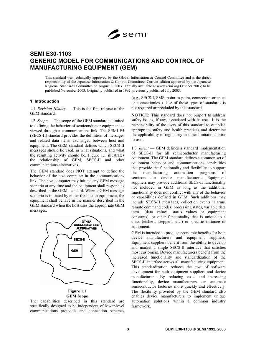
the resulting activity should be. Figure 1.1 illustrates
the
relationship of GEM, SECS-II and other
communications alternatives.
The GEM standard does NOT attempt to define the
behavior of the host computer in the communications
link. The host computer may initiate any GEM message
scenario at any time and the equipment shall respond as
described in the GEM standard. When a GEM message
scenario is initiated by either the host or equipment, the
equipment shall behave in the manner described in the
GEM standard when the host uses the appropriate GEM
messages.
Figure 1.1
GEM Scope
in
The capabilities described
this standard are
specifically designed to be independent of lower-level
communications protocols and connection schemes
(e.g., SECS-I, SMS, point-to-point, connection-oriented
or connectionless). Use of those types of standards is
not required or precluded by this standard.
NOTICE: This standard does not purport to address
safety issues, if any, associated with its use. It is the
responsibility of the users of this standard to establish
appropriate safety and health practices and determine
the applicability of regulatory or other limitations prior
to use.
programs
automation
1.3 Intent — GEM defines a standard implementation
of SECS-II for all semiconductor manufacturing
equipment. The GEM standard defines a common set of
equipment behavior and communications capabilities
that provide the functionality and flexibility to support
the manufacturing
of
semiconductor device manufacturers. Equipment
suppliers may provide additional SECS-II functionality
not included in GEM as long as the additional
functionality does not conflict with any of the behavior
or capabilities defined in GEM. Such additions may
include SECS-II messages, collection events, alarms,
remote command codes, processing states, variable data
items
(data values, status values or equipment
constants), or other functionality that is unique to a
class (etchers, steppers, etc.) or specific instance of
equipment.
GEM is intended to produce economic benefits for both
device manufacturers
suppliers.
Equipment suppliers benefit from the ability to develop
and market a single SECS-II interface that satisfies
most customers. Device manufacturers benefit from the
increased functionality and standardization of the
SECS-II interface across all manufacturing equipment.
This standardization reduces the cost of software
development for both equipment suppliers and device
manufacturers. By reducing costs and
increasing
functionality, device manufacturers can automate
semiconductor factories more quickly and effectively.
The flexibility provided by the GEM standard also
enables device manufacturers to implement unique
automation solutions within a common
industry
framework.
and
equipment
3
SEMI E30-1103 © SEMI 1992, 2003
�
The GEM standard is intended to specify the following:
— A model of the behavior to be exhibited by
in a
semiconductor manufacturing equipment
SECS-II communication environment,
— A description of information and control functions
semiconductor manufacturing
a
in
needed
environment,
— A definition of the basic SECS-II communications
semiconductor manufacturing
capabilities of
equipment,
— A single consistent means of accomplishing an
action when SECS-II provides multiple possible
methods, and
— Standard message dialogues necessary to achieve
useful communications capabilities.
The GEM standard contains two types of requirements:
— fundamental GEM requirements and
Equipment suppliers should work with their customers
to determine which additional GEM capabilities should
be implemented for a specific type of equipment.
Because the capabilities defined in the GEM standard
the factory
were specifically developed
semiconductor
automation
manufacturers,
that most device
manufacturers will
the GEM
capabilities that apply to a particular type of equipment.
Some device manufacturers may not require all the
GEM capabilities due to differences in their factory
automation strategies.
requirements
it
require most of
to meet
of
is anticipated
1.4 Overview — The GEM standard is divided into
sections as described below.
Section 1 — Introduction
This section provides the revision history, scope and
intent of the GEM standard. It also provides an
overview of the structure of the document and a list of
related documents.
— requirements of additional GEM capabilities.
Section 2 — Definitions
form
requirements
fundamental GEM
The
the
foundation of the GEM standard. The additional GEM
capabilities provide functionality required for some
types of factory automation or functionality applicable
to specific types of equipment. A detailed list of the
fundamental GEM requirements and additional GEM
capabilities can be found
in Chapter 8, GEM
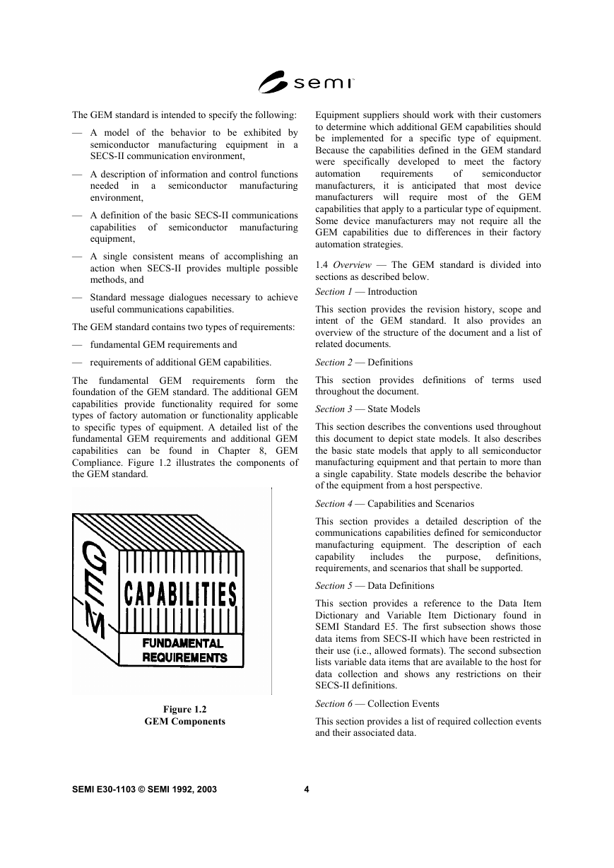
Compliance. Figure 1.2 illustrates the components of
the GEM standard.
This section provides definitions of
throughout the document.
terms used
Section 3 — State Models
This section describes the conventions used throughout
this document to depict state models. It also describes
the basic state models that apply to all semiconductor
manufacturing equipment and that pertain to more than
a single capability. State models describe the behavior
of the equipment from a host perspective.
Section 4 — Capabilities and Scenarios
This section provides a detailed description of the
communications capabilities defined for semiconductor
manufacturing equipment. The description of each
capability
definitions,
requirements, and scenarios that shall be supported.
purpose,
includes
the
Section 5 — Data Definitions
This section provides a reference to the Data Item
Dictionary and Variable Item Dictionary found in
SEMI Standard E5. The first subsection shows those
data items from SECS-II which have been restricted in
their use (i.e., allowed formats). The second subsection
lists variable data items that are available to the host for
data collection and shows any restrictions on their
SECS-II definitions.
Section 6 — Collection Events
This section provides a list of required collection events
and their associated data.
Figure 1.2
GEM Components
SEMI E30-1103 © SEMI 1992, 2003
4
�
Section 7 — SECS Message Subset
1.5 Applicable Documents
This section provides a composite list of the SECS-II
messages required to implement all capabilities defined
in the GEM standard.
Section 8 — GEM Compliance
the
section describes
This
fundamental GEM
requirements and additional GEM capabilities and
provides references to other sections of the standard
where detailed requirements are located. This section
also defines standard terminology and documentation
that can be used by equipment suppliers and device
manufacturers
this
standard.
to describe compliance with
Section A — Application Notes
These
provide
information and examples.
sections
additional
explanatory
Section A.1 — Factory Operational Script
This section provides an overview of how the required
SECS capabilities may be used in the context of a
typical factory operation sequence. This section is
organized according to the sequence in which actions
are typically performed.
Section A.2 — Equipment Front Panel
This section provides guidance in implementing the
required front panel buttons, indicators, and switches as
defined in this document. A summary of the front panel
requirements is provided.
Section A.3 — Examples of Equipment Alarms
This section provides examples of alarms related to
various equipment configurations.
Section A.4 — Trace Data Collection Example
This section provides an example of trace initialization
by the host and the periodic trace data messages that
might be sent by the equipment.
Section A.5 — Harel Notation
This section explains David Harel’s “Statechart”
notation that is used throughout this document to depict
state models.
Section A.6 — Example Control Model Application
This section provides one example of a host’s
interaction with an equipment’s control model.
Section A.7 — Examples of Limits Monitoring
This section contains four limits monitoring examples
to help clarify the use of limits and to illustrate typical
applications.
following SEMI
1.5.1 SEMI Standards — The
standards are related to the GEM standard. The specific
portions of
these standards referenced by GEM
constitute provisions of the GEM standard.
SEMI E4 — SEMI Equipment Communications
Standard 1 — Message Transfer (SECS-I)
SEMI E5 — SEMI Equipment Communications
Standard 2 — Message Content (SECS-II)
SEMI E13 — Standard
Communication Standard Message Service (SMS)
for SEMI Equipment
SEMI E23 — Specification for Cassette Transfer
Parallel I/O Interface
1.5.2 Other References
Harel, D., “Statecharts: A Visual Formalism for
Complex Systems,” Science of Computer Programming
8 (1987) 231-2741.
NOTICE: As listed or revised, all documents cited
shall be the latest publications of adopted standards.
2 Definitions
2.1 alarm — An alarm is related to any abnormal
situation on the equipment that may endanger people,
equipment, or material being processed. Such abnormal
situations are defined by the equipment manufacturer
based on physical safety
limitations. Equipment
activities potentially impacted by the presence of an
alarm shall be inhibited.
2.1.1 Note that exceeding control limits associated
with process tolerance does not constitute an alarm nor
do normal equipment events such as the start or
completion of processing.
2.2 capabilities — Capabilities
are operations
performed by semiconductor manufacturing equipment.
These
the
communications interface using sequences of SECS-II
messages (or scenarios). An example of a capability is
the setting and clearing of alarms.
operations
initiated
are
through
2.3 collection event — A collection event is an event
(or grouping of related events) on the equipment that is
considered to be significant to the host.
2.4 communication failure — A communication failure
is said to occur when an established communications
link is broken. Such failures are protocol specific. Refer
to the appropriate protocol standard (e.g., SEMI E4 or
1 Elsevier Science, P.O. Box 945, New York, NY 10159-0945,
http://www.elvesier.nl/homepage/browse.htt
5
SEMI E30-1103 © SEMI 1992, 2003
�
SEMI E37) for a protocol-specific definition of
communication failure.
2.5 communication fault — A communication fault
occurs when the equipment does not receive an
expected message, or when either a transaction timer or
a conversation timer expires.
2.6 control — To control is to exercise directing
influence.
2.7 equipment model — An equipment model is a
definition based on capabilities, scenarios, and SECS-II
messages that manufacturing equipment should perform
to support an automated manufacturing environment.
(See also Generic Equipment Model.)
2.8 event — An event is a detectable occurrence
significant to the equipment.
2.9 GEM compliance — The term “GEM Compliance”
is defined with respect to individual GEM capabilities
to indicate adherence to the GEM standard for a
specific capability. Section 8 includes more detail on
GEM Compliance.
2.10 Generic Equipment Model — The Generic
Equipment Model is used as a reference model for any
type of equipment. It contains functionality that can
apply to most equipment, but does not address unique
requirements of specific equipment.
2.11 host — The SEMI E4 and E5 standards define
Host as “the intelligent system that communicates with
the equipment.”
2.12 message fault — A message fault occurs when the
equipment receives a message that it cannot process
because of a defect in the message.
2.13 operational script — An operational script is a
collection of scenarios arranged in a sequence typical of
actual factory operations. Example sequences are
system initialization powerup, machine setup, and
processing.
2.14 operator — A human who operates the equipment
to perform its intended function (e.g., processing). The
operator typically interacts with the equipment via the
equipment supplied operator console.
2.15 process unit — A process unit refers to the
material that is typically processed as a unit via single
run command, process program, etc. Common process
units are wafers, cassettes, magazines, and boats.
2.16 processing cycle — A processing cycle is a
sequence wherein all of the material contained in a
typical process unit is processed. This is often used as a
measure of action or time.
SEMI E30-1103 © SEMI 1992, 2003
6
2.17 scenario — A scenario is a group of SECS-II
messages arranged
to perform a
capability. Other information may also be included in a
scenario for clarity.
in a sequence
2.18 SECS-I — SEMI Equipment Communications
Standard 1 (SEMI E4). This standard specifies a
method for a message transfer protocol with electrical
signal levels based upon EIA RS232-C.
2.19 SECS-II — SEMI Equipment Communications
Standard 2 (SEMI E5). This standard specifies a group
of messages and the respective syntax and semantics
for
relating
semiconductor
manufacturing equipment control.
those messages
to
2.20 SMS — SECS Message Service. An alternative to
SECS-I to be used when sending SECS-II formatted
messages over a network.
2.21 state model — A State Model is a collection of
states and state transitions that combine to describe the
behavior of a system. This model includes definition of
the
the
actions/reactions possible within a state, the events that
trigger transitions to other states, and the process of
transitioning between states.
conditions
delineate
that
a
state,
2.22 system default — Refers to state(s) in the
equipment behavioral model that are expected to be
active at the end of system initialization. It also refers to
the value(s) that specified equipment variables are
expected to contain at the end of system initialization.
2.23 system initialization — The process that an
equipment performs at power-up, system activation,
and/or system reset. This process is expected to prepare
the equipment to operate properly and according to the
equipment behavioral models.
2.24 user — A human or humans who represent the
factory and enforce the factory operation model. A user
is considered to be responsible for many setup and
configuration activities that cause the equipment to best
conform to factory operations practices.
3 State Models
The following sections contain state models for
semiconductor manufacturing equipment. These state
models describe the behavior of the equipment from a
host perspective in a compact and easy to understand
format. State models for different equipment will be
identical in some areas (e.g., communications), but may
vary in other areas (e.g., processing). It is desirable to
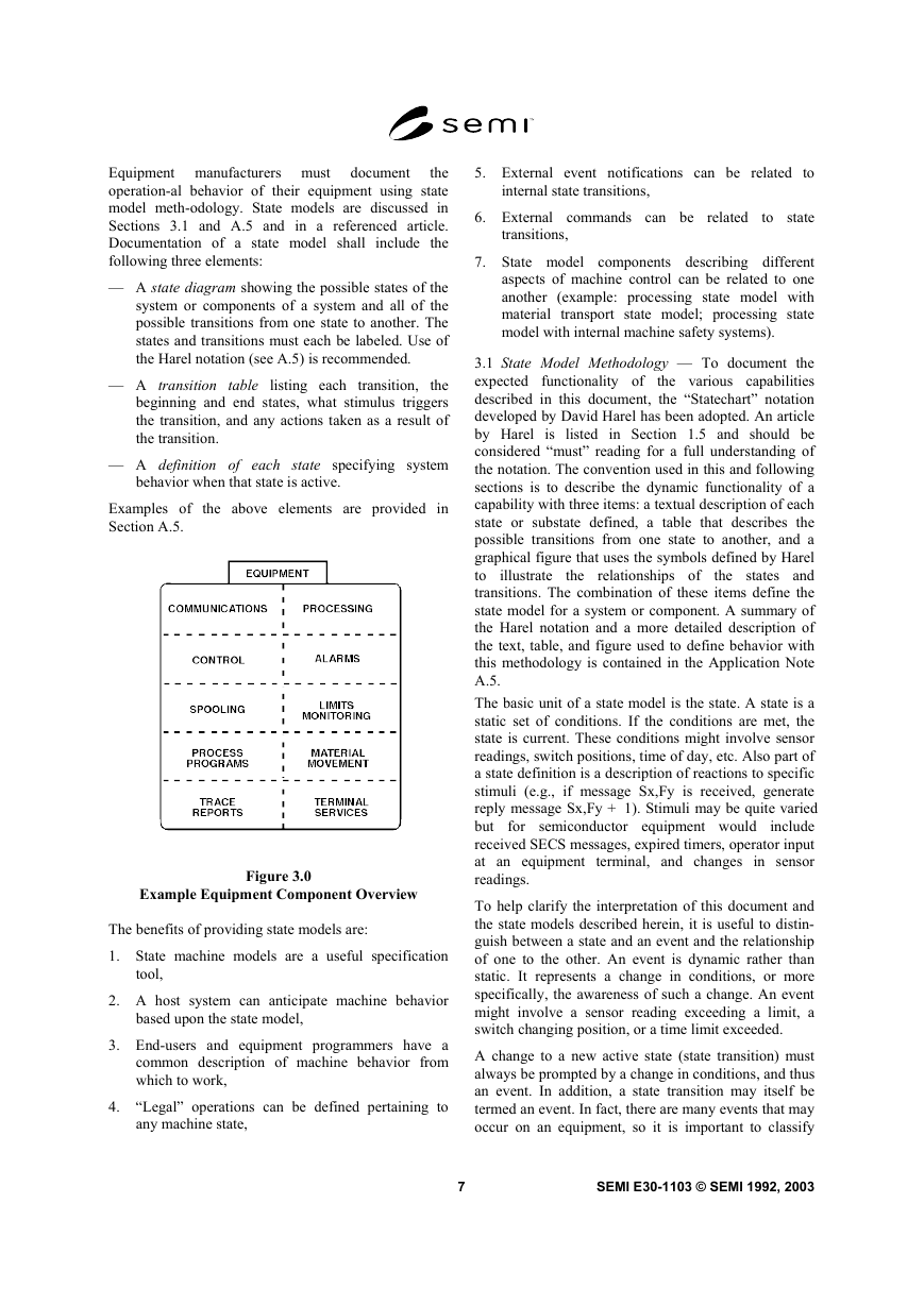
divide the equipment into parallel components that can
be modeled separately and then combined. An example
of a component overview of an equipment is provided
as Figure 3.0.
�
document
Equipment manufacturers must
the
operation-al behavior of their equipment using state
model meth-odology. State models are discussed in
Sections 3.1 and A.5 and in a referenced article.
Documentation of a state model shall include the
following three elements:
— A state diagram showing the possible states of the
system or components of a system and all of the
possible transitions from one state to another. The
states and transitions must each be labeled. Use of
the Harel notation (see A.5) is recommended.
— A transition table listing each transition, the
beginning and end states, what stimulus triggers
the transition, and any actions taken as a result of
the transition.
— A definition of each state specifying system
behavior when that state is active.
Examples of the above elements are provided in
Section A.5.
Example Equipment Component Overview
Figure 3.0
The benefits of providing state models are:
1. State machine models are a useful specification
tool,
2. A host system can anticipate machine behavior
based upon the state model,
3. End-users and equipment programmers have a
common description of machine behavior from
which to work,
4. “Legal” operations can be defined pertaining to
any machine state,
5. External event notifications can be related to
internal state transitions,
6. External commands can be related
to state
transitions,
7. State model components describing different
aspects of machine control can be related to one
another (example: processing state model with
material transport state model; processing state
model with internal machine safety systems).
illustrate
the relationships of
3.1 State Model Methodology — To document the
expected functionality of
the various capabilities
described in this document, the “Statechart” notation
developed by David Harel has been adopted. An article
by Harel is listed in Section 1.5 and should be
considered “must” reading for a full understanding of
the notation. The convention used in this and following
sections is to describe the dynamic functionality of a
capability with three items: a textual description of each
state or substate defined, a table that describes the
possible transitions from one state to another, and a
graphical figure that uses the symbols defined by Harel
to
the states and
transitions. The combination of these items define the
state model for a system or component. A summary of
the Harel notation and a more detailed description of
the text, table, and figure used to define behavior with
this methodology is contained in the Application Note
A.5.
The basic unit of a state model is the state. A state is a
static set of conditions. If the conditions are met, the
state is current. These conditions might involve sensor
readings, switch positions, time of day, etc. Also part of
a state definition is a description of reactions to specific
stimuli (e.g., if message Sx,Fy is received, generate
reply message Sx,Fy + 1). Stimuli may be quite varied
but for semiconductor equipment would
include
received SECS messages, expired timers, operator input
at an equipment terminal, and changes in sensor
readings.
To help clarify the interpretation of this document and
the state models described herein, it is useful to distin-
guish between a state and an event and the relationship
of one to the other. An event is dynamic rather than
static. It represents a change in conditions, or more
specifically, the awareness of such a change. An event
might involve a sensor reading exceeding a limit, a
switch changing position, or a time limit exceeded.
A change to a new active state (state transition) must
always be prompted by a change in conditions, and thus
an event. In addition, a state transition may itself be
termed an event. In fact, there are many events that may
occur on an equipment, so it is important to classify
7
SEMI E30-1103 © SEMI 1992, 2003
�
events based on whether they can be detected and
whether they are of interest. In this document, the term
event has been more narrowly defined as a detectable
occurrence that is significant to the equipment.
A further narrowing of the definition of event is repre-
sented by the term “collection event,” which is an event
(or group of related events) on the equipment that is
considered significant to the host. It is these events that
(if enabled) are reported to the host. By this definition,
the list of collection events for an equipment would typ-
ically be only a subset of total events. The state models
in this document are intended to be limited to the level
of detail in which the host is interested. Thus, all state
transitions defined in this standard, unless otherwise
specified, shall correspond to collection events.
State Model —
3.2 Communications
The
Communications State Model defines the behavior of
the equipment in relation to the existence or absence of
a communications link with the host. Section 4.1
expands on this section by defining the Establish
Communications capability. This model pertains to a
logical connection between equipment and host rather
than a physical connection.
3.2.1 Terminology — The terms communication fail-
ure, connection transaction failure, and communication
link are defined for use within this document only and
should not be confused with the same or similar terms
used elsewhere.
See SEMI E4 (SECS-I) or SEMI E37 (HSMS) for
a protocol specific definitions of communications
failure.
A connection transaction failure occurs when
attempting to establish communications and is
caused by
— a communication failure,
— the failure to receive an S1,F14 reply within a
reply timeout limit, or
— receipt of S1,F14 that has been improperly
formatted or with COMMACK2 not set to 0.
A reply timeout period begins after the successful
transmission of a complete primary message for
which a reply is expected. (See SEMI E4 (SECS-I)
or SEMI E37 (HSMS) for a protocol-specific
definition of reply timeout.)
A communication link is established following the
first successful completion of any one S1,F13/F14
transaction with an acknowledgement of “accept”.
The establishment of this link is logical rather than
physical.
Implementations may have mechanisms which
allow outgoing messages to be stored temporarily
prior to being sent. The noun queue is used to
cover such stored messages. They are queued when
placed within the queue and are dequeued by
removing them from this storage.
Send includes “queue to send” or “begin the
process of attempting to send” a message. It does
not imply the successful completion of sending a
message.
The host may attempt to establish communications
with equipment at any time due to the initialization
of the host or by independent detection of a
communications failure by the host. Thus, the host
may initiate an S1,F13/F14 transaction at any time.
3.2.2 CommDelay Timer — The CommDelay timer
represents an internal timer used to measure the interval
between attempts to send S1,F13. The length of this
interval is equal to the value in the EstablishCommuni-
cationsTimeout. The CommDelay timer is not directly
visible to the host.
EstablishCommunicationsTimeout is the user-configur-
able equipment constant that defines the delay, in
seconds, between attempts to send S1,F13. This value
is used to initialize the CommDelay timer.
The CommDelay timer is initialized to begin timing.
The CommDelay timer is initialized only when the state
WAIT DELAY is entered.
The CommDelay timer is expired when it “times out,”
and the time remaining in the interval between attempts
to send is zero. When the timer expires during the state
WAIT DELAY, it triggers a new attempt to send
S1,F13 and the transition to the state WAIT CRA3 .
3.2.3 Conventions
The attempt to send S1,F13 is made only upon
transit into the state WAIT CRA. The CommDelay
Timer should be set to “expired” at this time.
The CommDelay timer is initialized only upon
transit into the state WAIT DELAY. A next
2 Establish Communications Acknowledge Code, defined in Section
4.1. See the SEMI E5 Standard for further definition of this Data
Item.
3 CRA is the mnemonic defined for Establish Communications
Request Acknowledge (S1,F14).
SEMI E30-1103 © SEMI 1992, 2003
8
�


 2023年江西萍乡中考道德与法治真题及答案.doc
 2012年重庆南川中考生物真题及答案.doc
 2013年江西师范大学地理学综合及文艺理论基础考研真题.doc
 2020年四川甘孜小升初语文真题及答案I卷.doc
 2020年注册岩土工程师专业基础考试真题及答案.doc
 2023-2024学年福建省厦门市九年级上学期数学月考试题及答案.doc
 2021-2022学年辽宁省沈阳市大东区九年级上学期语文期末试题及答案.doc
 2022-2023学年北京东城区初三第一学期物理期末试卷及答案.doc
 2018上半年江西教师资格初中地理学科知识与教学能力真题及答案.doc
 2012年河北国家公务员申论考试真题及答案-省级.doc
 2020-2021学年江苏省扬州市江都区邵樊片九年级上学期数学第一次质量检测试题及答案.doc
 2022下半年黑龙江教师资格证中学综合素质真题及答案.doc