Bosch Sensortec | BMP388 Datasheet
1 | 57
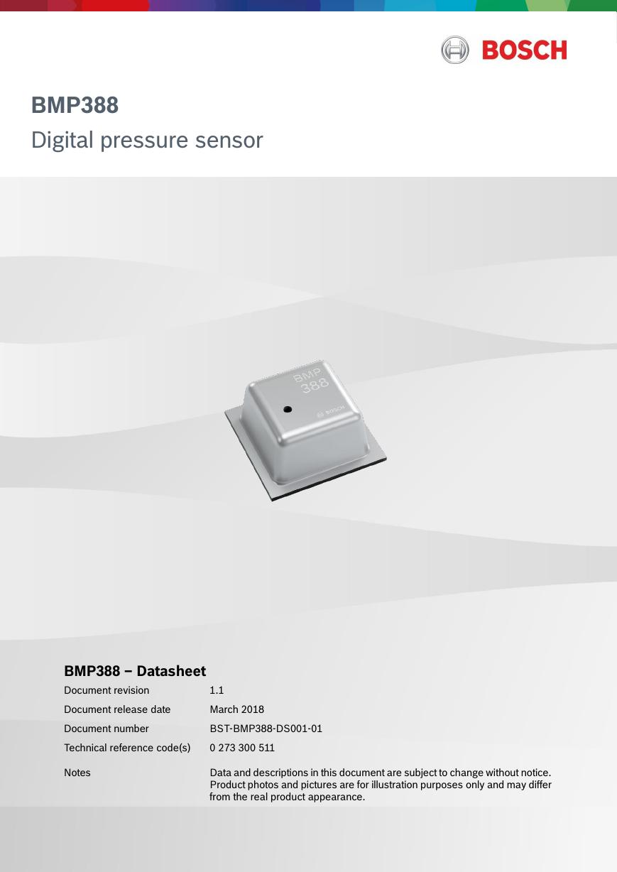
BMP388
Digital pressure sensor
BMP388 – Datasheet
Document revision
1.1
Document release date
March 2018
Document number
BST-BMP388-DS001-01
Technical reference code(s)
0 273 300 511
Notes
Data and descriptions in this document are subject to change without notice.
Product photos and pictures are for illustration purposes only and may differ
from the real product appearance.
Modifications reserved |Data subject not change without notice | Printed in Germany
Document number: BST-BMEP388-DS001-01 Revision_1.1_032018
�
Bosch Sensortec | BMP388 Datasheet
BMP388
Digital pressure sensor
2 | 57
The BMP388 is a digital sensor with pressure and temperature measurement based on proven sensing principles. The sensor
module is housed in an extremely compact 10-pin metal-lid LGA package with a footprint of only 2.0 × 2.0 mm² and max 0.8
mm package height. Its small dimensions and its low power consumption of 3.4 µA @1Hz allow the implementation in battery
driven devices such as mobile phones, GPS modules or watches.
Typical applications
Vertical velocity indication (e.g. rise/sink speed)
Internet of things
Enhancement of GPS navigation
(e.g. time-to-first-fix improvement, dead-reckoning, slope detection)
Indoor navigation & localization (floor detection, elevator detection)
Outdoor navigation, leisure and sports applications
Weather forecast
Health care applications (e.g. spirometry)
Fitness applications like enhancement of calorie detection
AR & VR applications
Context awareness
Target Devices
Flying toys
Drones
Handsets such as mobile phones, tablet PCs, GPS devices
Navigation systems
Portable health care devices
Home weather stations
Watches
White goods
Modifications reserved |Data subject not change without notice | Printed in Germany
Document number: BST-BMEP388-DS001-01 Revision_1.1_032018
�
Bosch Sensortec | BMP388 Datasheet
Key features
3 | 57
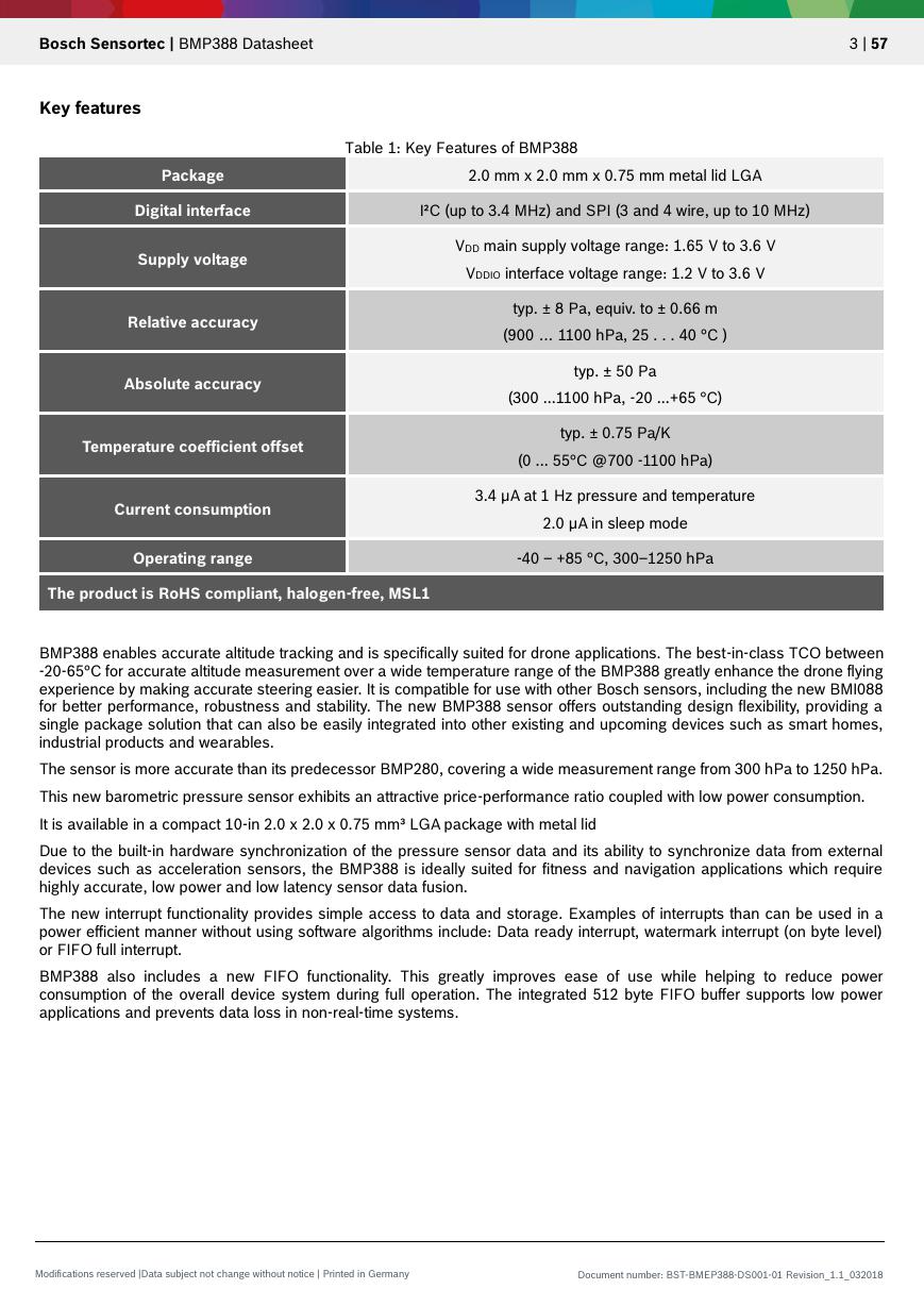
Package
2.0 mm x 2.0 mm x 0.75 mm metal lid LGA
Table 1: Key Features of BMP388
Digital interface
I²C (up to 3.4 MHz) and SPI (3 and 4 wire, up to 10 MHz)
Supply voltage
Relative accuracy
Absolute accuracy
Temperature coefficient offset
Current consumption
VDD main supply voltage range: 1.65 V to 3.6 V
VDDIO interface voltage range: 1.2 V to 3.6 V
typ. ± 8 Pa, equiv. to ± 0.66 m
(900 … 1100 hPa, 25 . . . 40 °C )
typ. ± 50 Pa
(300 ...1100 hPa, -20 ...+65 °C)
typ. ± 0.75 Pa/K
(0 ... 55°C @700 -1100 hPa)
3.4 µA at 1 Hz pressure and temperature
2.0 µA in sleep mode
Operating range
-40 ‒ +85 °C, 300‒1250 hPa
The product is RoHS compliant, halogen-free, MSL1
BMP388 enables accurate altitude tracking and is specifically suited for drone applications. The best-in-class TCO between
-20-65°C for accurate altitude measurement over a wide temperature range of the BMP388 greatly enhance the drone flying
experience by making accurate steering easier. It is compatible for use with other Bosch sensors, including the new BMI088
for better performance, robustness and stability. The new BMP388 sensor offers outstanding design flexibility, providing a
single package solution that can also be easily integrated into other existing and upcoming devices such as smart homes,
industrial products and wearables.
The sensor is more accurate than its predecessor BMP280, covering a wide measurement range from 300 hPa to 1250 hPa.
This new barometric pressure sensor exhibits an attractive price-performance ratio coupled with low power consumption.
It is available in a compact 10-in 2.0 x 2.0 x 0.75 mm³ LGA package with metal lid
Due to the built-in hardware synchronization of the pressure sensor data and its ability to synchronize data from external
devices such as acceleration sensors, the BMP388 is ideally suited for fitness and navigation applications which require
highly accurate, low power and low latency sensor data fusion.
The new interrupt functionality provides simple access to data and storage. Examples of interrupts than can be used in a
power efficient manner without using software algorithms include: Data ready interrupt, watermark interrupt (on byte level)
or FIFO full interrupt.
BMP388 also includes a new FIFO functionality. This greatly improves ease of use while helping to reduce power
consumption of the overall device system during full operation. The integrated 512 byte FIFO buffer supports low power
applications and prevents data loss in non-real-time systems.
Modifications reserved |Data subject not change without notice | Printed in Germany
Document number: BST-BMEP388-DS001-01 Revision_1.1_032018
�
Bosch Sensortec | BMP388 Datasheet
4 | 57
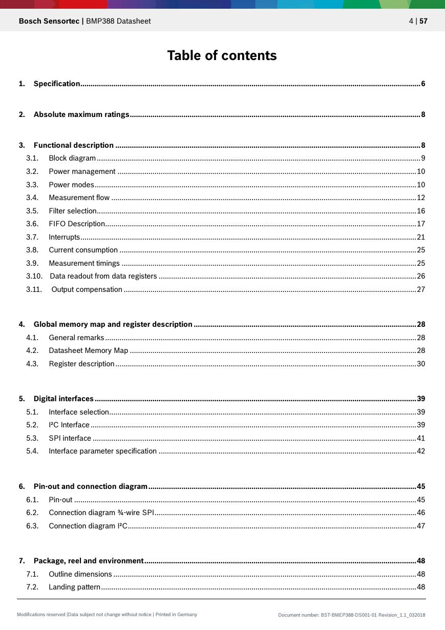
Table of contents
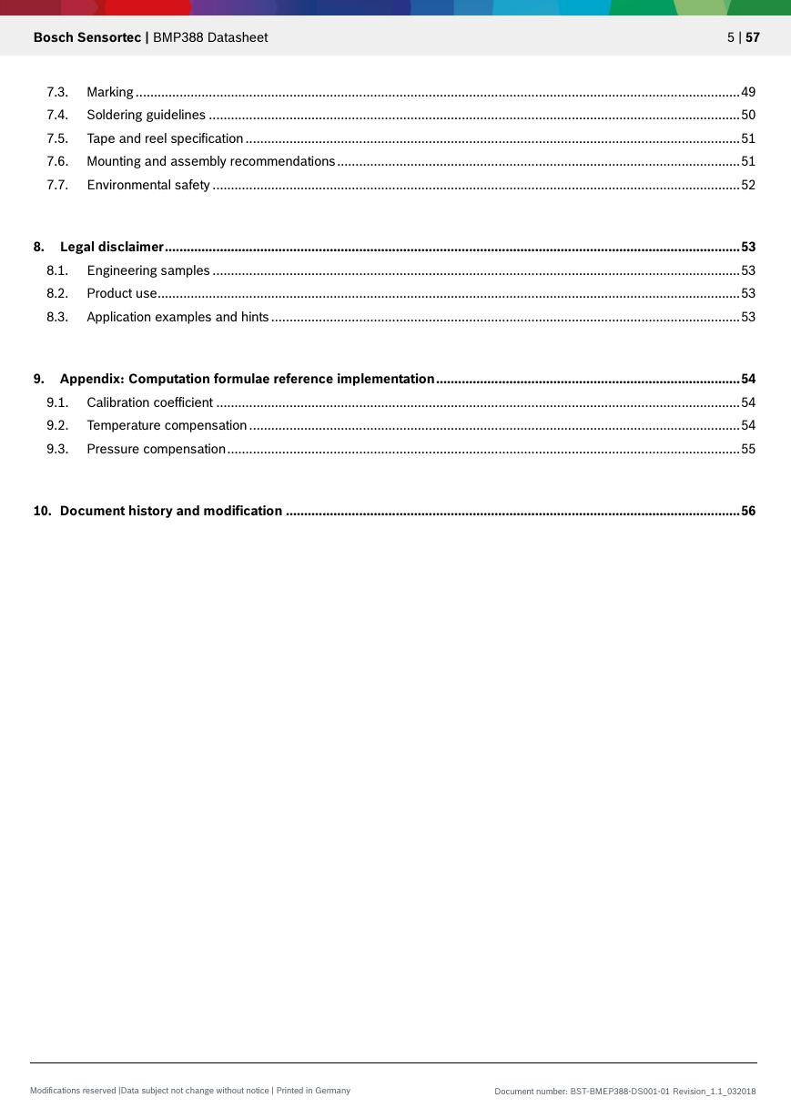
1. Specification ..................................................................................................................................................................... 6
2. Absolute maximum ratings ............................................................................................................................................. 8
3. Functional description .................................................................................................................................................... 8
3.1. Block diagram ............................................................................................................................................................. 9
3.2. Power management ................................................................................................................................................. 10
3.3. Power modes ............................................................................................................................................................ 10
3.4. Measurement flow .................................................................................................................................................... 12
3.5. Filter selection ........................................................................................................................................................... 16
3.6. FIFO Description....................................................................................................................................................... 17
3.7.
Interrupts ................................................................................................................................................................... 21
3.8. Current consumption ................................................................................................................................................ 25
3.9. Measurement timings ............................................................................................................................................... 25
3.10. Data readout from data registers ............................................................................................................................. 26
3.11. Output compensation .............................................................................................................................................. 27
4. Global memory map and register description ............................................................................................................ 28
4.1. General remarks ....................................................................................................................................................... 28
4.2. Datasheet Memory Map ........................................................................................................................................... 28
4.3. Register description .................................................................................................................................................. 30
5. Digital interfaces ............................................................................................................................................................ 39
5.1.
Interface selection..................................................................................................................................................... 39
5.2.
I²C Interface .............................................................................................................................................................. 39
5.3. SPI interface ............................................................................................................................................................. 41
5.4.
Interface parameter specification ............................................................................................................................. 42
6. Pin-out and connection diagram .................................................................................................................................. 45
6.1. Pin-out ...................................................................................................................................................................... 45
6.2. Connection diagram ¾-wire SPI ............................................................................................................................... 46
6.3. Connection diagram I²C ............................................................................................................................................ 47
7. Package, reel and environment .................................................................................................................................... 48
7.1. Outline dimensions ................................................................................................................................................... 48
7.2. Landing pattern ......................................................................................................................................................... 48
Modifications reserved |Data subject not change without notice | Printed in Germany
Document number: BST-BMEP388-DS001-01 Revision_1.1_032018
�
Bosch Sensortec | BMP388 Datasheet
5 | 57
7.3. Marking ..................................................................................................................................................................... 49
7.4. Soldering guidelines ................................................................................................................................................. 50
7.5. Tape and reel specification ....................................................................................................................................... 51
7.6. Mounting and assembly recommendations .............................................................................................................. 51
7.7. Environmental safety ................................................................................................................................................ 52
8. Legal disclaimer ............................................................................................................................................................. 53
8.1. Engineering samples ................................................................................................................................................ 53
8.2. Product use ............................................................................................................................................................... 53
8.3. Application examples and hints ................................................................................................................................ 53
9. Appendix: Computation formulae reference implementation ................................................................................... 54
9.1. Calibration coefficient ............................................................................................................................................... 54
9.2. Temperature compensation ...................................................................................................................................... 54
9.3. Pressure compensation ............................................................................................................................................ 55
10. Document history and modification ............................................................................................................................ 56
Modifications reserved |Data subject not change without notice | Printed in Germany
Document number: BST-BMEP388-DS001-01 Revision_1.1_032018
�
Bosch Sensortec | BMP388 Datasheet
1. Specification
If not stated otherwise,
6 | 57
All values are valid over the full voltage range
All minimum/maximum values are given for the full accuracy temperature range
Minimum/maximum values of drifts, offsets and temperature coefficients are ±3 values over lifetime
Typical values of currents and state machine timings are determined at 25 °C
Typical values of currents and state machine timings are determined at 25°C. minimum/maximum values of currents
are determined at -40°C/85°C.
Minimum/maximum values of state machine timings are determined using corner lots over 0…+65 °C temperature
range.
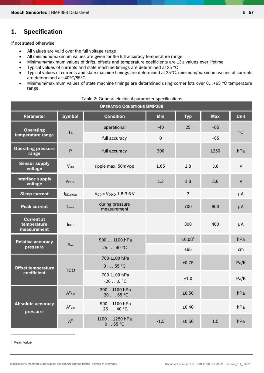
Table 2: General electrical parameter specifications
OPERATING CONDITIONS BMP388
Parameter
Symbol
Condition
Operating
temperature range
Operating pressure
range
TA
P
operational
full accuracy
full accuracy
Min
-40
0
300
Typ
25
Max
Unit
+85
+65
°C
1250
hPa
Sensor supply
voltage
Interface supply
voltage
VDD
ripple max. 50mVpp
1.65
1.8
VDDIO
1.2
3.6
3.6
1.8
2
V
V
µA
µA
700
800
300
400
µA
±0.081
±66
±0.75
±1.0
±0.50
±0.40
hPa
cm
Pa/K
Pa/K
hPa
hPa
-1.5
±0.50
1.5
hPa
Sleep current
IDD,sleep
VDD = VDDIO 1.8-3.6 V
during pressure
measurement
900 … 1100 hPa
25 . . . 40 °C
700-1100 hPa
0 . . . 55 °C
700-1100 hPa
-20 . . .0 °C
300. . 1100 hPa
-20 . . . 65 °C
900. . 1100 hPa
25 . . . 40 °C
1100 . . 1250 hPa
0 . . 65 °C
Peak current
Ipeak
Current at
temperature
measurement
Relative accuracy
pressure
IDDT
Arel
Offset temperature
coefficient
TCO
Absolute accuracy
pressure
AP
full
AP
ext
AP
1 Mean value
Modifications reserved |Data subject not change without notice | Printed in Germany
Document number: BST-BMEP388-DS001-01 Revision_1.1_032018
�
Bosch Sensortec | BMP388 Datasheet
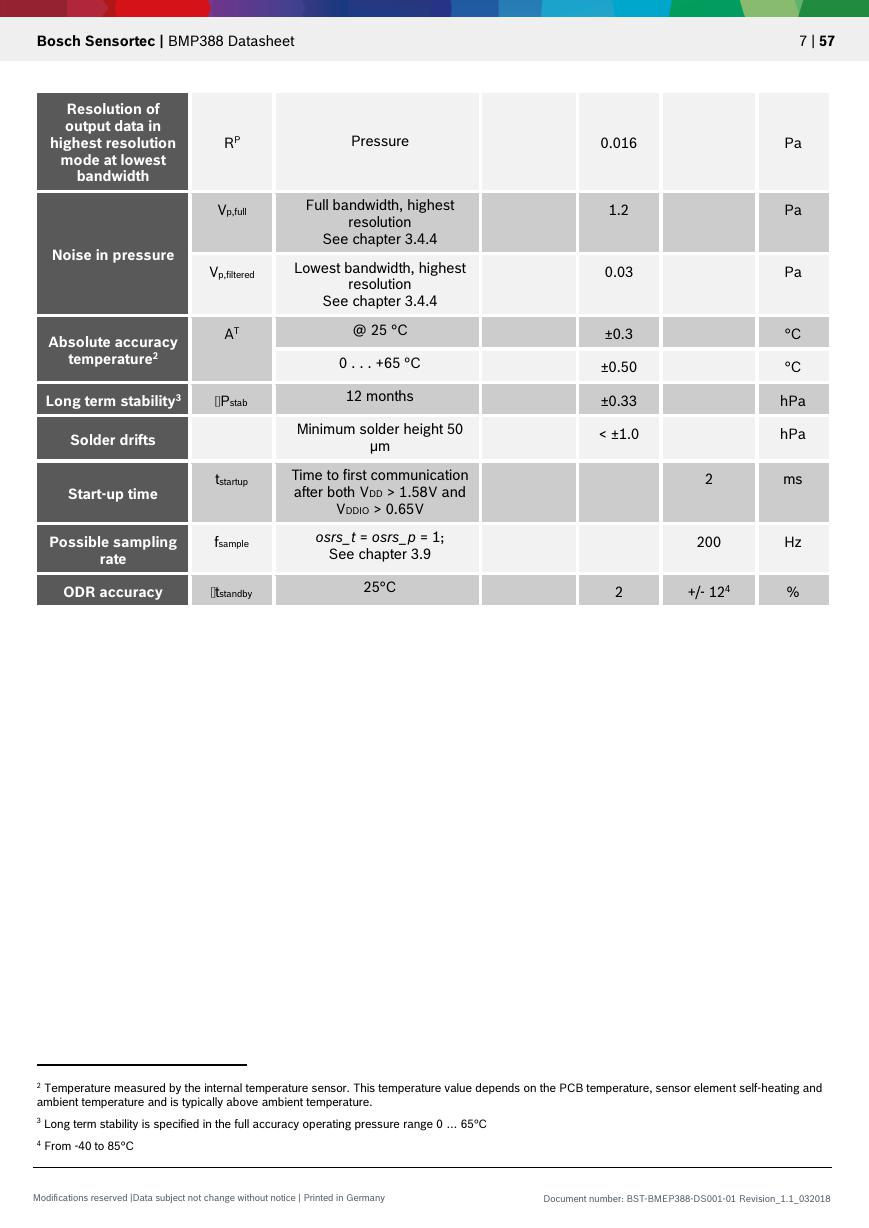
RP
Pressure
Resolution of
output data in
highest resolution
mode at lowest
bandwidth
Noise in pressure
Absolute accuracy
temperature2
Vp,full
Vp,filtered
AT
Full bandwidth, highest
resolution
See chapter 3.4.4
Lowest bandwidth, highest
resolution
See chapter 3.4.4
@ 25 °C
0 . . . +65 °C
12 months
Long term stability3
Pstab
Solder drifts
Start-up time
tstartup
Minimum solder height 50
µm
Time to first communication
after both VDD > 1.58V and
VDDIO > 0.65V
Possible sampling
fsample
rate
osrs_t = osrs_p = 1;
See chapter 3.9
ODR accuracy
tstandby
25°C
7 | 57
Pa
Pa
Pa
°C
°C
hPa
hPa
2
ms
200
Hz
0.016
1.2
0.03
±0.3
±0.50
±0.33
< ±1.0
2
+/- 124
%
2 Temperature measured by the internal temperature sensor. This temperature value depends on the PCB temperature, sensor element self-heating and
ambient temperature and is typically above ambient temperature.
3 Long term stability is specified in the full accuracy operating pressure range 0 … 65°C
4 From -40 to 85°C
Modifications reserved |Data subject not change without notice | Printed in Germany
Document number: BST-BMEP388-DS001-01 Revision_1.1_032018
�
Bosch Sensortec | BMP388 Datasheet
8 | 57
2. Absolute maximum ratings
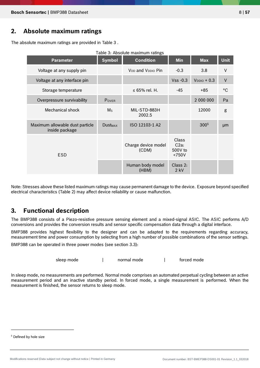
The absolute maximum ratings are provided in Table 3 .
Table 3: Absolute maximum ratings
Parameter
Symbol
Condition
Min
Max
Unit
Voltage at any supply pin
Voltage at any interface pin
Storage temperature
VDD and VDDIO Pin
-0.3
3.8
Vss -0.3 VDDIO + 0.3
V
V
≤ 65% rel. H.
-45
+85
°C
Overpressure survivability
POVER
Mechanical shock
MS
MIL-STD-883H
2002.5
Maximum allowable dust particle
DustMAX
ISO 12103-1 A2
inside package
2 000 000
Pa
12000
g
3005
µm
ESD
Charge device model
(CDM)
Class
C2a:
500V to
<750V
Human body model
Class 2:
(HBM)
2 kV
Note: Stresses above these listed maximum ratings may cause permanent damage to the device. Exposure beyond specified
electrical characteristics (Table 2) may affect device reliability or cause malfunction.
3. Functional description
The BMP388 consists of a Piezo-resistive pressure sensing element and a mixed-signal ASIC. The ASIC performs A/D
conversions and provides the conversion results and sensor specific compensation data through a digital interface.
BMP388 provides highest flexibility to the designer and can be adapted to the requirements regarding accuracy,
measurement time and power consumption by selecting from a high number of possible combinations of the sensor settings.
BMP388 can be operated in three power modes (see section 3.3):
sleep mode
|
normal mode
|
forced mode
In sleep mode, no measurements are performed. Normal mode comprises an automated perpetual cycling between an active
measurement period and an inactive standby period. In forced mode, a single measurement is performed. When the
measurement is finished, the sensor returns to sleep mode.
5 Defined by hole size
Modifications reserved |Data subject not change without notice | Printed in Germany
Document number: BST-BMEP388-DS001-01 Revision_1.1_032018
�


 V2版本原理图(Capacitive-Fingerprint-Reader-Schematic_V2).pdf
 摄像头工作原理.doc
 VL53L0X简要说明(En.FLVL53L00216).pdf
 原理图(DVK720-Schematic).pdf
 原理图(Pico-Clock-Green-Schdoc).pdf
 原理图(RS485-CAN-HAT-B-schematic).pdf
 File:SIM7500_SIM7600_SIM7800 Series_SSL_Application Note_V2.00.pdf
 ADS1263(Ads1262).pdf
 原理图(Open429Z-D-Schematic).pdf
 用户手册(Capacitive_Fingerprint_Reader_User_Manual_CN).pdf
 CY7C68013A(英文版)(CY7C68013A).pdf
 TechnicalReference_Dem.pdf