HD COLOR CAMERA
HDC3300R
OPERATION MANUAL [English]
1st Edition (Revised 1)
�
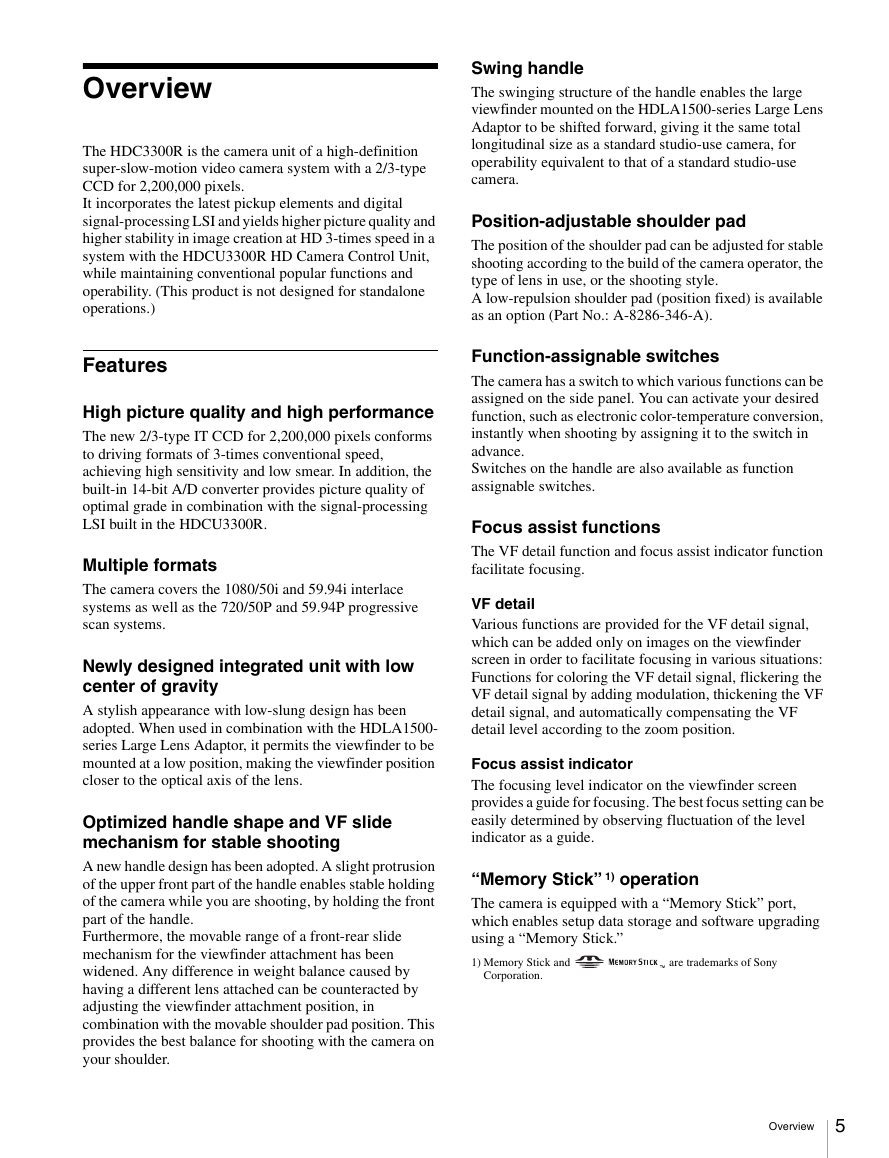
WARNING
To reduce the risk of fire or electric shock,
do not expose this apparatus to rain or
moisture.
To avoid electrical shock, do not open the
cabinet. Refer servicing to qualified
personnel only.
AVERTISSEMENT
Afin de réduire les risques d’incendie ou
d’électrocution, ne pas exposer cet
appareil à la pluie ou à l’humidité.
Afin d’écarter tout risque d’électrocution,
garder le coffret fermé. Ne confier
l’entretien de l’appareil qu’à un personnel
qualifié.
WARNUNG
Um die Gefahr von Bränden oder
elektrischen Schlägen zu verringern, darf
dieses Gerät nicht Regen oder Feuchtigkeit
ausgesetzt werden.
Um einen elektrischen Schlag zu
vermeiden, darf das Gehäuse nicht
geöffnet werden. Überlassen Sie
Wartungsarbeiten stets nur qualifiziertem
Fachpersonal.
For the customers in the U.S.A.
This equipment has been tested and found to comply with the
limits for a Class A digital device, pursuant to Part 15 of the
FCC Rules. These limits are designed to provide reasonable
protection against harmful interference when the equipment is
operated in a commercial environment. This equipment
generates, uses, and can radiate radio frequency energy and,
if not installed and used in accordance with the instruction
manual, may cause harmful interference to radio
communications. Operation of this equipment in a residential
area is likely to cause harmful interference in which case the
user will be required to correct the interference at his own
expense.
You are cautioned that any changes or modifications not
expressly approved in this manual could void your authority to
operate this equipment.
All interface cables used to connect peripherals must be
shielded in order to comply with the limits for a digital device
pursuant to Subpart B of Part 15 of FCC Rules.
For the customers in Europe
This product with the CE marking complies with both the EMC
Directive and the Low Voltage Directive issued by the
Commission of the European Community.
Compliance with these directives implies conformity to the
following European standards:
• EN60950-1: Product Safety
EN55103-1: Electromagnetic Interference (Emission)
EN55103-2: Electromagnetic Susceptibility (Immunity)
This product is intended for use in the following
Electromagnetic Environments:
E1 (residential), E2 (commercial and light industrial), E3
(urban outdoors), E4 (controlled EMC environment, ex. TV
studio).
The manufacturer of this product is Sony Corporation, 1-7-1
Konan, Minato-ku, Tokyo, Japan.
The Authorized Representative for EMC and product safety is
Sony Deutschland GmbH, Hedelfinger Strasse 61, 70327
Stuttgart, Germany. For any service or guarantee matters
please refer to the addresses given in separate service or
guarantee documents.
Pour les clients en Europe
Ce produit portant la marque CE est conforme à la fois à la
Directive sur la compatibilité électromagnétique (EMC) et à la
Directive sur les basses tensions émises par la Commission
de la Communauté Européenne.
La conformité à ces directives implique la conformité aux
normes européennes suivantes:
EN60950-1 : Sécurité des produits
EN55103-1 : Interférences électromagnétiques (émission)
EN55103-2 : Sensibilité électromagnétique (immunité)
Ce produit est prévu pour être utilisé dans le senvironnements
électromagnétiques suivants : E1 (résidentiel), E2
(commercial et industrie légère), E3 (urbain extérieur) et E4
(environnement EMC contrôlé, ex. studio de télévision).
Le fabricant de ce produit est Sony Corporation, 1-7-1 Konan,
Minato-ku, Tokyo, Japon.
Le représentant autorisé pour EMC et la sécurité des produits
est Sony Deutschland GmbH, Hedelfinger Strasse 61, 70327
Stuttgart, Allemagne. Pour toute question concernant le
service ou lagarantie, veuillez consulter les adresses
indiquées dans les documents de service ou de garantie
séparés.
Für Kunden in Europa
Dieses Produkt besitzt die CE-Kennzeichnung und erfüllt die
EMV-Richtlinie sowie die Niederspannungsrichtlinie der EG-
Kommission.
Angewandte Normen:
EN60950-1: Sicherheitsbestimmungen
EN55103-1: Elektromagnetische Verträglichkeit
(Störaussendung)
EN55103-2: Elektromagnetische Verträglichkeit
(Störfestigkeit)
Für die folgenden elektromagnetischen Umgebungen:
E1 (Wohnbereich), E2 (kommerzieller und in beschränktem
Maße industrieller Bereich), E3 (Stadtbereich im Freien) und
E4 (kontrollierter EMV-Bereich, z.B. Fernsehstudio).
2
�
Der Hersteller dieses Produkts ist Sony Corporation, 1-7-1
Konan, Minato-ku, Tokyo, Japan.
Der autorisierte Repräsentant für EMV und Produktsicherheit
ist Sony Deutschland GmbH, Hedelfinger Strasse 61, 70327
Stuttgart, Deutschland. Bei jeglichen Angelegenheiten in
Bezug auf Kundendienst oder Garantie wenden Sie sich bitte
an die in den separaten Kundendienst- oder
Garantiedokumenten aufgeführten Anschriften.
For the State of California, USA only
Perchlorate Material - special handling may apply, See
www.dtsc.ca.gov/hazardouswaste/perchlorate
Perchlorate Material : Lithium battery contains perchlorate.
For the customers in Taiwan only
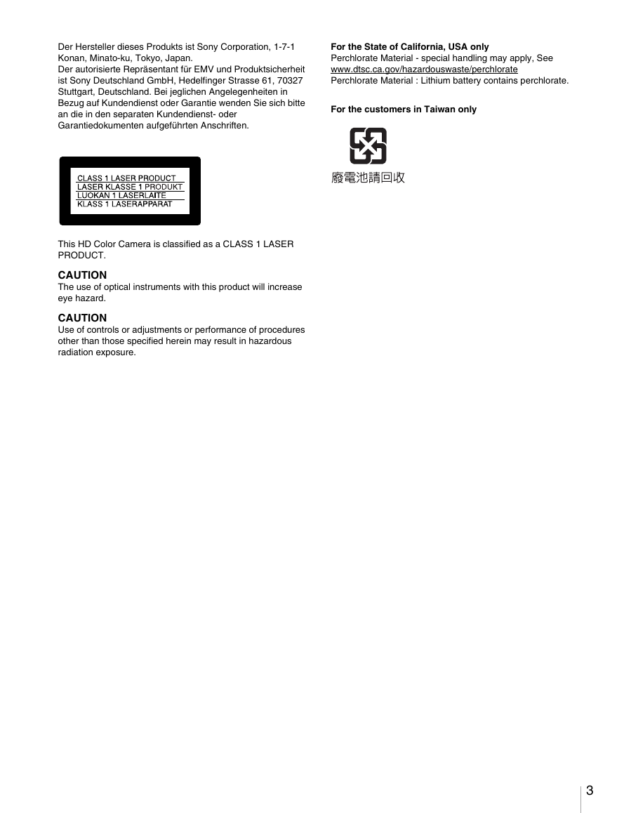
This HD Color Camera is classified as a CLASS 1 LASER
PRODUCT.
CAUTION
The use of optical instruments with this product will increase
eye hazard.
CAUTION
Use of controls or adjustments or performance of procedures
other than those specified herein may result in hazardous
radiation exposure.
3
�
Table of Contents
Overview ................................................................................. 5
Features........................................................................................5
System Configuration Example...................................................7
Precautions ............................................................................ 8
Phenomena Specific to CCD Image Sensors...............................8
Locations and Functions of Parts ........................................ 9
Accessory Attachments ...............................................................9
Controls and Connectors ...........................................................10
Preparations ......................................................................... 17
Attaching a Lens........................................................................17
Adjusting the Flange Focal Length ...........................................17
Attaching a Viewfinder .............................................................18
Attaching the Cable Clamp Belt (Supplied)..............................20
Adjusting the Shoulder Pad Position.........................................21
Mounting the Camera to a Tripod .............................................21
Adjustments and Settings for Shooting ............................ 22
Adjusting the Black Balance and White Balance......................22
Setting the Electronic Shutter....................................................24
Setting the Focus Assist Functions............................................24
Setting the Flicker-Reduction Function.....................................26
Viewfinder Screen Status Display ...................................... 28
Menu Operations.................................................................. 29
Starting Menu Operations..........................................................29
Selecting Pages..........................................................................30
Setting the Menu Items..............................................................31
Editing the USER Menu............................................................32
Menu List .............................................................................. 36
OPERATION Menu ..................................................................36
PAINT Menu .............................................................................42
MAINTENANCE Menu ...........................................................46
FILE Menu ................................................................................49
DIAGNOSIS Menu ...................................................................51
Using a “Memory Stick” ...................................................... 52
Specifications....................................................................... 53
4 Table of Contents
�
Overview
The HDC3300R is the camera unit of a high-definition
super-slow-motion video camera system with a 2/3-type
CCD for 2,200,000 pixels.
It incorporates the latest pickup elements and digital
signal-processing LSI and yields higher picture quality and
higher stability in image creation at HD 3-times speed in a
system with the HDCU3300R HD Camera Control Unit,
while maintaining conventional popular functions and
operability. (This product is not designed for standalone
operations.)
Features
High picture quality and high performance
The new 2/3-type IT CCD for 2,200,000 pixels conforms
to driving formats of 3-times conventional speed,
achieving high sensitivity and low smear. In addition, the
built-in 14-bit A/D converter provides picture quality of
optimal grade in combination with the signal-processing
LSI built in the HDCU3300R.
Multiple formats
The camera covers the 1080/50i and 59.94i interlace
systems as well as the 720/50P and 59.94P progressive
scan systems.
Newly designed integrated unit with low
center of gravity
A stylish appearance with low-slung design has been
adopted. When used in combination with the HDLA1500-
series Large Lens Adaptor, it permits the viewfinder to be
mounted at a low position, making the viewfinder position
closer to the optical axis of the lens.
Optimized handle shape and VF slide
mechanism for stable shooting
A new handle design has been adopted. A slight protrusion
of the upper front part of the handle enables stable holding
of the camera while you are shooting, by holding the front
part of the handle.
Furthermore, the movable range of a front-rear slide
mechanism for the viewfinder attachment has been
widened. Any difference in weight balance caused by
having a different lens attached can be counteracted by
adjusting the viewfinder attachment position, in
combination with the movable shoulder pad position. This
provides the best balance for shooting with the camera on
your shoulder.
Swing handle
The swinging structure of the handle enables the large
viewfinder mounted on the HDLA1500-series Large Lens
Adaptor to be shifted forward, giving it the same total
longitudinal size as a standard studio-use camera, for
operability equivalent to that of a standard studio-use
camera.
Position-adjustable shoulder pad
The position of the shoulder pad can be adjusted for stable
shooting according to the build of the camera operator, the
type of lens in use, or the shooting style.
A low-repulsion shoulder pad (position fixed) is available
as an option (Part No.: A-8286-346-A).
Function-assignable switches
The camera has a switch to which various functions can be
assigned on the side panel. You can activate your desired
function, such as electronic color-temperature conversion,
instantly when shooting by assigning it to the switch in
advance.
Switches on the handle are also available as function
assignable switches.
Focus assist functions
The VF detail function and focus assist indicator function
facilitate focusing.
VF detail
Various functions are provided for the VF detail signal,
which can be added only on images on the viewfinder
screen in order to facilitate focusing in various situations:
Functions for coloring the VF detail signal, flickering the
VF detail signal by adding modulation, thickening the VF
detail signal, and automatically compensating the VF
detail level according to the zoom position.
Focus assist indicator
The focusing level indicator on the viewfinder screen
provides a guide for focusing. The best focus setting can be
easily determined by observing fluctuation of the level
indicator as a guide.
“Memory Stick” 1) operation
The camera is equipped with a “Memory Stick” port,
which enables setup data storage and software upgrading
using a “Memory Stick.”
1) Memory Stick and
Corporation.
are trademarks of Sony
Overview
5
�
Various color-reproduction functions (in
combination with HDCU3300R)
Selection of multiple gamma tables
Seven types of standard and 4 types of hyper gamma tables
are provided with this camera. The hyper gamma values
enable cinemalike image creations with wide dynamic
range, which are different from those achieved with
conventional video gamma.
Multimatrix color correction
In addition the standard 6-axis matrix function, the camera
has a multimatrix function that permits you to adjust the
hue and chroma for color components in 16-axis directions
independently. This is quite useful in color matching
among multiple cameras.
Knee saturation
Change of hue and decrease in chroma that occur in
highlighted areas can be compensated.
This enables reproduction of natural skin tones under
strong lighting.
Low key saturation
Hue and saturation in low-key zones can be compensated.
Thus, compensation for color reproduction in all zones is
enabled in combination with matrix color compensation
and knee saturation functions.
Versatile detail control functions (in
combination with HDCU3300R)
Skin-tone detail function
This function allows control (emphasis or suppression) of
the detail level for just a certain hue or chroma area in the
image, by creating a detail gate signal from color
components of your specified hue, such as skin tones.
The detail levels of three hues can be adjusted
independently at the same time.
Detail boost-frequency control
The boost frequency can be adjusted from 20 to 30 MHz.
This allows the detail thickness to be set appropriately for
the subject, thus enabling more subtle image expression.
H/V ratio control
The ratio between horizontal and vertical detail can be
adjusted.
White/black limiter
The white and black details can be limited independently.
Flicker-reduction function
Flicker may occur in slow-motion playback of images
recorded at 3 times normal speed. Variations in the video
6 Overview
levels caused by the power-supply frequency for artificial
lighting under which shooting is undertaken are not
averaged across the fields during supermotion shooting,
with which exposure time is one-third that with normal
speed shooting. This may result in differences in video
levels to be played back, i.e., a phenomenon called flicker.
To reduce flicker, this camera system is provided for the
flicker-reduction function, with which real-time
processing for averaging differences in video levels across
fields is performed.
Easy menu-based setting
Selections and settings for viewfinder display items,
safety-zone marker 2) or center marker,3) screen size
marker, etc. can be made quickly and easily, using setup
menus displayed on the viewfinder screen or an external
monitor.
2) Safety zone marker:
A box-shaped marker displayed on the viewfinder screen which indicates
80%, 90%, 92.5%, or 95% of the total screen area
3) Center marker:
A cross-shaped marker which indicates the center of the viewfinder screen
Wide variety of viewfinder display options
Along with items such as operation messages, a zebra
pattern,4) a safety-zone marker, and a center marker,
camera settings may also be displayed on the viewfinder
screen. Furthermore, there are other indicators arranged
above and below the viewfinder, such as a tally lamp,
battery warning indicator, and an indicator to tell you that
one or more settings are other than standard. This makes it
simple to check the status of the camera.
4) Zebra pattern:
A stripe pattern displayed on the viewfinder screen which indicates the
portions where the video level is above about 70% or 100%. Used to check
the video level of the subject.
New 10-gigabit optical digital transmission
The camera uses electro-optical coding cable for 10-
gigabit optical digital transmission between the camera
and a Camera Control Unit.
High-resolution monochrome and color
multiformat viewfinders (optional)
The HDVF-20A/200 multiformat 2-type monochrome
CRT viewfinders and the HDVF-C35W (3.5-type) /
HDVF-C30WR (2.7-type) multiformat color LCD
viewfinders are available as options to cover various
applications.
Prevention of electrical shock
When the power connection is unsafe, the power supply
from the connected Camera Control Unit will be shut off.
�
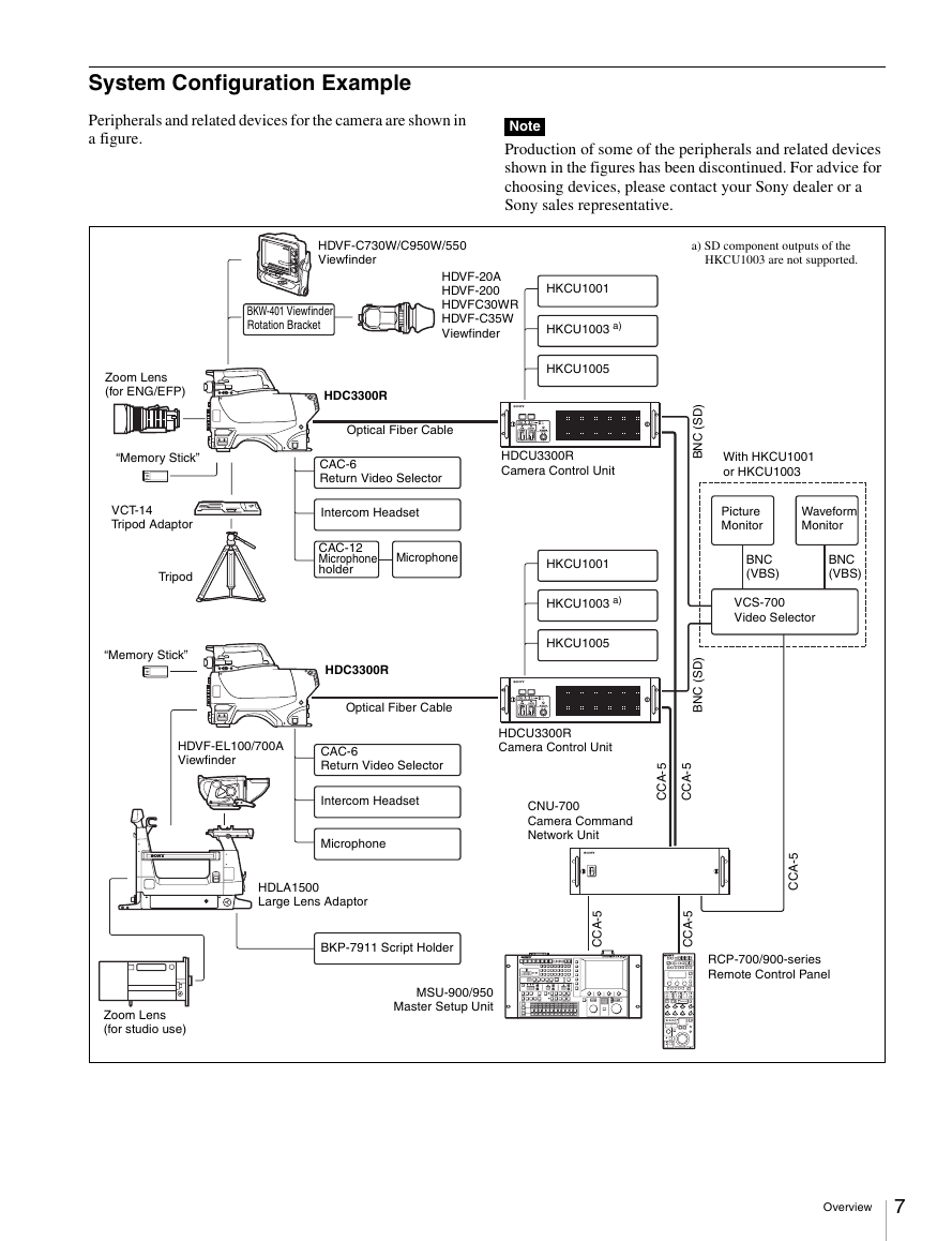
System Configuration Example
Peripherals and related devices for the camera are shown in
a figure.
Note
Production of some of the peripherals and related devices
shown in the figures has been discontinued. For advice for
choosing devices, please contact your Sony dealer or a
Sony sales representative.
HDVF-C730W/C950W/550
Viewfinder
a) SD component outputs of the
HKCU1003 are not supported.
BKW-401 Viewfinder
Rotation Bracket
HDVF-20A
HDVF-200
HDVFC30WR
HDVF-C35W
Viewfinder
HKCU1001
HKCU1003 a)
HKCU1005
HDC3300R
Optical Fiber Cable
CAC-6
Return Video Selector
Intercom Headset
CAC-12
Microphone
holder
Microphone
HDC3300R
Optical Fiber Cable
HDCU3300R
Camera Control Unit
HKCU1001
HKCU1003 a)
HKCU1005
With HKCU1001
or HKCU1003
Picture
Monitor
Waveform
Monitor
BNC
(VBS)
BNC
(VBS)
VCS-700
Video Selector
)
D
S
(
C
N
B
)
D
S
(
C
N
B
Zoom Lens
(for ENG/EFP)
“Memory Stick”
VCT-14
Tripod Adaptor
Tripod
“Memory Stick”
HDVF-EL100/700A
Viewfinder
CAC-6
Return Video Selector
Intercom Headset
Microphone
HDLA1500
Large Lens Adaptor
BKP-7911 Script Holder
MSU-900/950
Master Setup Unit
Zoom Lens
(for studio use)
HDCU3300R
Camera Control Unit
5
-
A
C
C
5
-
A
C
C
CNU-700
Camera Command
Network Unit
5
-
A
C
C
5
-
A
C
C
5
-
A
C
C
RCP-700/900-series
Remote Control Panel
Overview
7
�
when operating at a high environmental temperature
when you have raised the master gain (sensitivity)
This product has a compensation function and the problem
may be alleviated by automatic black balance adjustment
(see page 22).
Smear
When an extremely bright object, such as a strong spotlight
or flashlight, is being shot, vertical tails may be produced
on the screen, or the image may be distorted.
Aliasing
When fine patterns, stripes, or lines are shot, they may
appear jagged or flicker.
Precautions
Note on laser beams
Laser beams may damage the CCDs. If you shoot a scene
that includes a laser beam, be careful not to let a laser beam
become directed into the lens of the camera.
Do not subject to severe shocks
Damage to the case or internal components may result.
When finished using
Set the power switch to OFF.
Operation and storage environment
Store in a level place with air conditioning.
If the unit gets wet, make sure it is completely dry before
storage.
Avoid use or storage in the following places:
Extremely hot or cold places
Places with high humidity
Places with strong vibration
Near strong magnetic fields
In places where it receives much direct sunlight, or near
heating equipment
Condensation
If you move the camera from a very cold place to a warm
place, or use it in a damp location, condensation may form
on the lens or inside the camera.
The camera has no built-in condensation indicator. If you
find condensation on the body or lens, switch the camera
off and wait for the condensation to disappear for about
one hour.
Phenomena Specific to CCD Image
Sensors
The following phenomena that may appear in images are
specific to CCD (Charge Coupled Device) image sensors.
They do not indicate malfunctions.
White flecks
Although the CCD image sensors are produced with high-
precision technologies, fine white flecks may be generated
on the screen in rare cases, caused by cosmic rays.
This is related to the principle of CCD image sensors and
is not a malfunction.
The white flecks especially tend to be seen
8 Precautions
�



 2023年江西萍乡中考道德与法治真题及答案.doc
 2012年重庆南川中考生物真题及答案.doc
 2013年江西师范大学地理学综合及文艺理论基础考研真题.doc
 2020年四川甘孜小升初语文真题及答案I卷.doc
 2020年注册岩土工程师专业基础考试真题及答案.doc
 2023-2024学年福建省厦门市九年级上学期数学月考试题及答案.doc
 2021-2022学年辽宁省沈阳市大东区九年级上学期语文期末试题及答案.doc
 2022-2023学年北京东城区初三第一学期物理期末试卷及答案.doc
 2018上半年江西教师资格初中地理学科知识与教学能力真题及答案.doc
 2012年河北国家公务员申论考试真题及答案-省级.doc
 2020-2021学年江苏省扬州市江都区邵樊片九年级上学期数学第一次质量检测试题及答案.doc
 2022下半年黑龙江教师资格证中学综合素质真题及答案.doc