MOTOCAL V32
OPERATOR’S MANUAL
VERSION 4.10 or LATER
Upon receipt of the product and prior to initial operation, read these instructions thoroughly and retain
for future reference.
Part Number:
Revision:
165139-1CD
1
MANUAL NO.
HW9482359
4
1/61�
General Precautions
・ Diagrams and photos in this manual are used as examples only and may differ from the actual delivered
product.
・ This manual may be modified when necessary because of improvement of the product, modification, or
changes in specifications.
Such modification is made as a revision by renewing the manual No.
・ To order a copy of this manual, if your copy has been damaged or lost, contact your YASKAWA
representative listed on the last page stating the manual No. on the front page.
・ YASKAWA is not responsible for any modification of the product made by the user since that will void
our guarantee.
・ Software supplied with this manuals intended for use by licensed operators only and may only be used or
copied according to the provisions of the license.
・ Reproduction of any part of this manual without the consent of YASKAWA is forbidden.
©YASKAWA, 1997
2/61�
CONTENTS
PREFACE ----------------------------------------------------------------- 4
4
4
4
Outline of MOTOVALV32 -----------------------------------------------------------------
Requirements for MOTOCALV32 Execution -----------------------------------------
MOTOCALV32 Setup ---------------------------------------------------------------------
1. TYPES OF CALIBRATION ---------------------------------------- 5
5
5
5
5
5
1.1 Robot Calibration -----------------------------------------------------------------------
1.2 Tool Calibration -------------------------------------------------------------------------
1.3 Tool Posture Calibration --------------------------------------------------------------
1.4 Workpiece Calibration -----------------------------------------------------------------
1.5 Layout Correction ----------------------------------------------------------------------
2. OPERATION -----------------------------------------------------------
2.1 Robot Calibration ------------------------------------------------------------------------
2.1.1 Operation with Actual Robot ---------------------------------------------------
2.1.2 Operation on Personal Computer ---------------------------------------------
2.2 Tool Calibration ----------------------------------------------------------------------------
2.2.1 Operation with Actual Robot ---------------------------------------------------
2.2.2 Operation on Personal Computer ---------------------------------------------
2.3 Tool Posture Calibration ----------------------------------------------------------------
2.3.1 Operation with Actual Robot ----------------------------------------------------
2.3.2 Operation on Personal Computer ----------------------------------------------
2.4 Workpiece Calibration -------------------------------------------------------------------
2.4.1 Workpiece Calibration ------------------------------------------------------------
2.4.2 Job Conversion ---------------------------------------------------------------------
2.5 Layout Correction --------------------------------------------------------------------------
2.5.1 Robot Layout Correction ----------------------------------------------------------
2.5.2 Travel Axis Correction -------------------------------------------------------------
6
6
6
9
16
16
17
20
20
21
24
24
29
34
34
40
APPENDIX ------------------------------------------------------------------
Appendix 1. Examples of Robot Calibration --------------------------------------------
Appendix 2. Examples of Tool Calibration -----------------------------------------------
47
47
53
3/61�
PREFACE
Outline of MOTOCALV32
The MOTOCALV32 has been developed to improve positioning accuracy of YASKAWA’s industrial
robot MOTOMAN. The MOTOCALV32 is an application software for MS-Windows, which offers
excellent operability on various types of personal computers.
Requirements for MOTOCALV32 Execution
OS
Required Memory
CPU
Hardware disk
MS-Windows 95/98/NT4.0(SP3 or more)*2)/2000 *1
16 Mbytes or more
Pentium90 MHz or more
15 Mbytes or more
Capacity
Screen
Mouse
Screen supported by Windows (256 colors or more)
Mouse supported by Windows
*1) MS-Windows95, MS-Windows98, MS-Windows NT4.0, MS-Windows 2000 are trade marks of
Microsoft Corporation, U.S.A.
*2) Service Packs 3 or more must be used for Microsoft Windows NT4.0.
MOTOCALV32 Setup
1. Turn ON the power to the personal computer and screen.
2. Start the Windows.
3.
4. Select the [Control Panel] of [Setting] from the [Start] button in the menu of task bar, then select the
Insert the install CD-ROM to the CD-ROM drive.
[Add/Delete Application].
5. Click the [Set-up] button and set "MOTOCALV32¥Disk1¥setup.exe" of the CD-ROM drive,
following to the instructions displayed in the screen.
6. Clicking the [Complete] button starts the installation program. Follow the instructions displayed in
the screen.
7. At
the
completion
of
setup,
the
[MOTOCALV32]
icon
is displayed
in
the
[Start]-[Program]-[Motoman]-[MOTOCALV32].
4/61�
1.TYPES OF CALIBRATION
The following types of calibrations are available for MOTOCALV32.
1.1 Robot Calibration
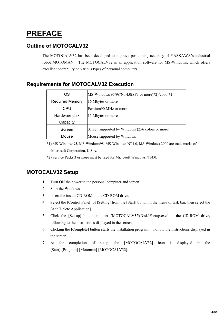
Adjusts the absolute data and tool data, by teaching 5 postures each of 5 points (total 25 points) with robot.
This calibration improves the absolute value accuracy of robot.
1.2 Tool Calibration
Adjusts tool data by teaching 7 postures at 1 point (total 7 points) with robot. This calibration calculates
the exact tool data (robot control point).
1.3 Tool Posture Calibration
Adjusts tool data by teaching 1 posture at 1 point (total 1 point) with robot. This calibration calculates
the exact tool positions (Rx, Ry, and Rz).
1.4 Workpiece Calibration
Recognizes the positional difference between each robot and workpiece, by comparing the job created by
offline system and the job created with the actual robot. Then converts the position data by offline
system into the data for the actual robot, using the difference above.
1.5 Layout Correction
The layout correction is composed of "Robot Layout Correction" and "Travel Axis Tilt Correction."
"Robot Layout Correction" corrects the robot layout in the cell constructed by ROTSY for actual robot
layout, by comparing the job created by offline system and the job created with the actual robot. "Travel
Axis Tilt Correction" corrects the robot layout in the cell constructed by ROTSY for the actual robot
layout, by calculating the positional difference between the travel axis and the robot positioned on the
travel axis.
5/61�
2.OPERATION
This chapter explains the operation method of each calibration by MOTOCALV32.
2.1 Robot Calibration
2.1.1 Operation with Actual Robot
1) To perform robot calibration, prepare the data of tool to be mounted in advance.
The following three methods are available for tool data.
Performs the tool calibration with the actual robot controller.
Performs the tool calibration by MOTOCALV32.
(Refer to Section 2.2 "Tool Calibration.")
Uses the values of mechanical dimensions if specified in the drawing, etc.
2) Mount an end-pointed tool on the robot flange.
Use a tool with pointed-end part offset to the direction of X- or Y-axis on the tool coordinate.
(Offset amount of approx. 200 mm is recommended.)
3) Using this tool, perform teaching of the job (job name: ROBOT) for 5 postures each of 5 points
(total 25 points). The calibration job "ROBOT" is used for actual calculation by the calibration
software.
The teaching method is explained below.
a) Using the same tool, perform teaching of 5 postures at each 5 point.
(Use MOVJ or MOVL for interpolation type. On base of the taught positions, X, Y, and Z
will be calculated internally.)
Notes 1: For teaching of large-size robots of K60 and more, perform teaching with the
wrist angle 45 or less, since the flexure by the robot arm weight may affect
calibration, with the wrist posture largely inclined. For robot sizes below K60,
incline the wrist 45 or more.
2: When the actual playback operation requires movement changing robot form,
for example, the robot wrist axis rotating in reverse, perform teaching with the
posture of that movement.
6/61�
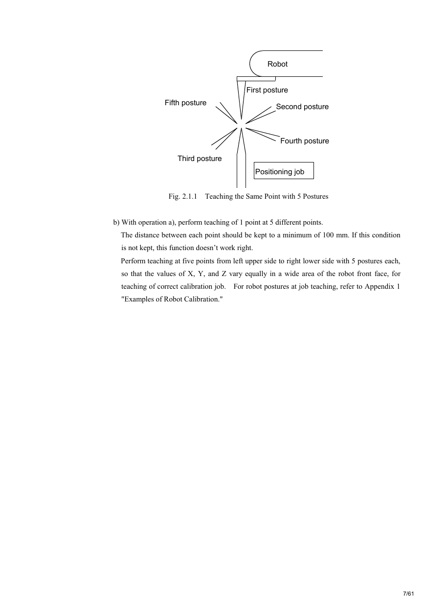
Fig. 2.1.1 Teaching the Same Point with 5 Postures
b) With operation a), perform teaching of 1 point at 5 different points.
The distance between each point should be kept to a minimum of 100 mm. If this condition
is not kept, this function doesn’t work right.
Perform teaching at five points from left upper side to right lower side with 5 postures each,
so that the values of X, Y, and Z vary equally in a wide area of the robot front face, for
teaching of correct calibration job. For robot postures at job teaching, refer to Appendix 1
"Examples of Robot Calibration."
Robot Positioning job First posture Second posture Third posture Fourth posture Fifth posture 7/61�
NOP
*1
MOVJ C0000 VJ=0.78 PL=0
MOVJ C0001 VJ=0.78 PL=0
MOVJ C0002 VJ=0.78 PL=0
MOVJ C0003 VJ=0.78 PL=0
MOVJ C0004 VJ=0.78 PL=0
*2
MOVJ C0005 VJ=0.78 PL=0
MOVJ C0006 VJ=0.78 PL=0
MOVJ C0007 VJ=0.78 PL=0
MOVJ C0008 VJ=0.78 PL=0
MOVJ C0009 VJ=0.78 PL=0
*3
MOVJ C0010 VJ=0.78 PL=0
MOVJ C0011 VJ=0.78 PL=0
MOVJ C0012 VJ=0.78 PL=0
MOVJ C0013 VJ=0.78 PL=0
MOVJ C0014 VJ=0.78 PL=0
*4
MOVJ C0015 VJ=0.78 PL=0
MOVJ C0016 VJ=0.78 PL=0
MOVJ C0017 VJ=0.78 PL=0
MOVJ C0018 VJ=0.78 PL=0
MOVJ C0019 VJ=0.78 PL=0
*5
MOVJ C0020 VJ=0.78 PL=0
MOVJ C0021 VJ=0.78 PL=0
MOVJ C0022 VJ=0.78 PL=0
MOVJ C0023 VJ=0.78 PL=0
MOVJ C0024 VJ=0.78 PL=0
END
Fig. 2.1.2 Teaching 5 Points with 5 Postures
Positioning jigRobotP1P2P3P4P5RobotPositioning jig8/61�



 2023年江西萍乡中考道德与法治真题及答案.doc
 2012年重庆南川中考生物真题及答案.doc
 2013年江西师范大学地理学综合及文艺理论基础考研真题.doc
 2020年四川甘孜小升初语文真题及答案I卷.doc
 2020年注册岩土工程师专业基础考试真题及答案.doc
 2023-2024学年福建省厦门市九年级上学期数学月考试题及答案.doc
 2021-2022学年辽宁省沈阳市大东区九年级上学期语文期末试题及答案.doc
 2022-2023学年北京东城区初三第一学期物理期末试卷及答案.doc
 2018上半年江西教师资格初中地理学科知识与教学能力真题及答案.doc
 2012年河北国家公务员申论考试真题及答案-省级.doc
 2020-2021学年江苏省扬州市江都区邵樊片九年级上学期数学第一次质量检测试题及答案.doc
 2022下半年黑龙江教师资格证中学综合素质真题及答案.doc