DATA SHEETProduct specificationFile under Integrated Circuits, IC06December1990INTEGRATED CIRCUITS74HC/HCT20Dual 4-input NAND gateFor a complete data sheet, please also download:•The IC06 74HC/HCT/HCU/HCMOS Logic Family Specifications•The IC06 74HC/HCT/HCU/HCMOS Logic Package Information•The IC06 74HC/HCT/HCU/HCMOS Logic Package Outlines�
December19902Philips SemiconductorsProduct specificationDual 4-input NAND gate74HC/HCT20FEATURES•Output capability: standard•ICC category: SSIGENERAL DESCRIPTIONThe 74HC/HCT20 are high-speed Si-gate CMOS devices and are pin compatible with low power Schottky TTL (LSTTL).They are specified in compliance with JEDEC standard no. 7A. The 74HC/HCT20 provide the 4-input NAND function.QUICK REFERENCE DATAGND=0V; Tamb=25C; tr=tf=6nsNotes1.CPD is used to determine the dynamic power dissipation (PD inmW):PD=CPD·VCC2·fi+(CL·VCC2·fo) where:fi=input frequency in MHzfo= output frequency in MHzCL=output load capacitance in pFVCC=supply voltage in V(CL·VCC2·fo) = sum of outputs2.For HCthe condition is VI=GND to VCCFor HCT the condition is VI=GND to VCC-1.5VORDERING INFORMATIONSee“74HC/HCT/HCU/HCMOS Logic Package Information”.SYMBOLPARAMETERCONDITIONSTYPICALUNITHCHCTtPHL/ tPLHpropagation delay nA, nB, nC, nD to nYCL=15pF; VCC=5V813nsCIinput capacitance3.53.5pFCPDpower dissipation capacitance per packagenotes 1 and 22217pF�
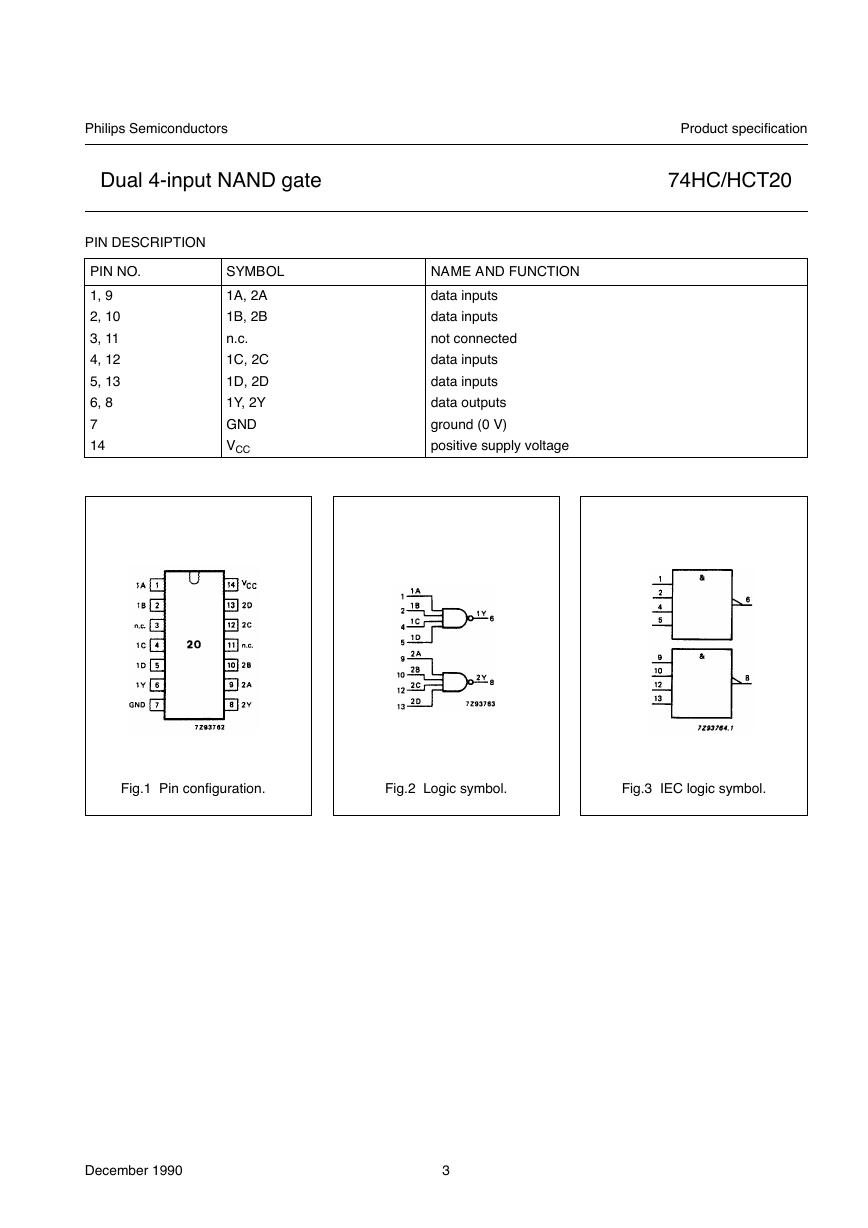
December19903Philips SemiconductorsProduct specificationDual 4-input NAND gate74HC/HCT20PIN DESCRIPTIONPIN NO.SYMBOLNAME AND FUNCTION1, 91A, 2Adata inputs2, 101B, 2Bdata inputs3, 11n.c.not connected4, 121C, 2Cdata inputs5, 131D, 2Ddata inputs6, 81Y, 2Ydata outputs7GNDground (0V)14VCCpositive supply voltageFig.1 Pin configuration.Fig.2 Logic symbol.Fig.3 IEC logic symbol.�
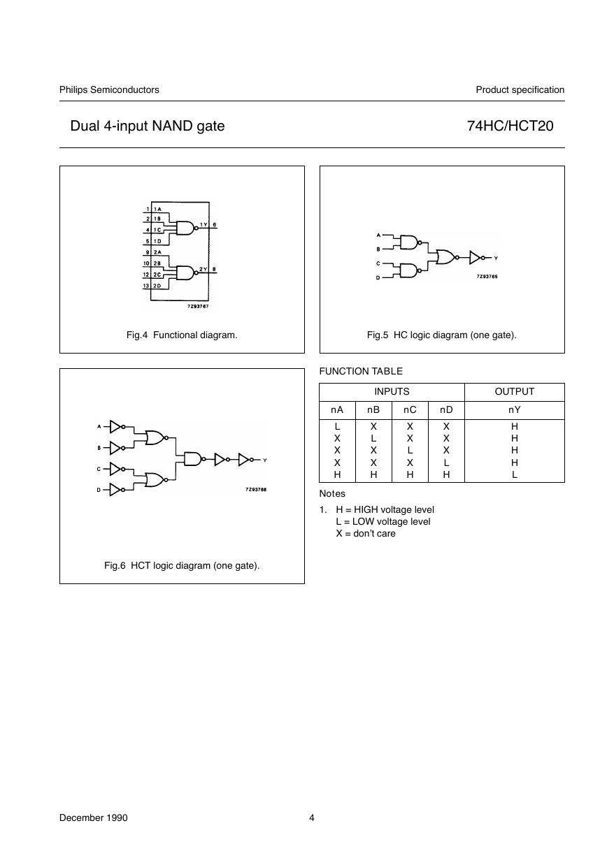
December19904Philips SemiconductorsProduct specificationDual 4-input NAND gate74HC/HCT20Fig.4 Functional diagram.Fig.5 HC logic diagram (one gate).Fig.6 HCT logic diagram (one gate).FUNCTION TABLENotes1.H=HIGH voltage levelL=LOW voltage levelX=don’t careINPUTSOUTPUTnAnBnCnDnYLXXXHXLXXHXXLXHXXXLHHHHHL�
December19905Philips SemiconductorsProduct specificationDual 4-input NAND gate74HC/HCT20DC CHARACTERISTICS FOR 74HCFor the DC characteristics see“74HC/HCT/HCU/HCMOS Logic Family Specifications”.Output capability: standardICC category: SSIAC CHARACTERISTICS FOR 74HCGND=0 V; tr=tf=6ns; CL=50pFSYMBOLPARAMETERTamb (C)TEST CONDITIONS74HCUNITVCC(V)WAVEFORMS+25-40to +85-40to +125min.typ.max.min.max.min.max.tPHL/ tPLHpropagation delaynA, nB, nC, nD to nY2810890181511523201352723ns2.04.56.0Fig.7tTHL/ tTLHoutput transition time19767515139519161102219ns2.04.56.0Fig.7�
December19906Philips SemiconductorsProduct specificationDual 4-input NAND gate74HC/HCT20DC CHARACTERISTICS FOR 74HCTFor the DC characteristics see“74HC/HCT/HCU/HCMOS Logic Family Specifications”.Output capability: standardICC category: SSINote to HCT typesThe value of additional quiescent supply current (DICC) for a unit load of 1 is given in the family specifications.To determineDICC per input, multiply this value by the unit load coefficient shown in the table below.AC CHARACTERISTICS FOR 74HCTGND=0V; tr=tf=6ns; CL=50pFAC WAVEFORMSPACKAGE OUTLINESSee“74HC/HCT/HCU/HCMOS Logic Package Outlines”.INPUTUNIT LOAD COEFFICIENTnA, nB, nC, nD0.3SYMBOLPARAMETERTamb (C)TEST CONDITIONS74HCTUNITVCC(V)WAVEFORMS+25-40to +85-40to +125min.typ.max.min.max.min.max.tPHL/ tPLHpropagation delaynA, nB, nC, nD to nY16283542ns4.5Fig.7tTHL/ tTLHoutput transition time7151922ns4.5Fig.7Fig.7Waveforms showing the enable input (nA, nB, nC, nD) to output (nY) propagation delays and the outputtransition times.(1)HC: VM=50%; VI=GNDto VCC.HCT: VM=1.3V;VI=GND to 3V.�
All Datasheets Cannot Be Modified Without Permission Copyright © Each Manufacturing Company This datasheet has been downloaded from: www.EEworld.com.cn Free Download Daily Updated Database 100% Free Datasheet Search Site 100% Free IC Replacement Search Site Convenient Electronic Dictionary Fast Search System www.EEworld.com.cn �


 V2版本原理图(Capacitive-Fingerprint-Reader-Schematic_V2).pdf
 摄像头工作原理.doc
 VL53L0X简要说明(En.FLVL53L00216).pdf
 原理图(DVK720-Schematic).pdf
 原理图(Pico-Clock-Green-Schdoc).pdf
 原理图(RS485-CAN-HAT-B-schematic).pdf
 File:SIM7500_SIM7600_SIM7800 Series_SSL_Application Note_V2.00.pdf
 ADS1263(Ads1262).pdf
 原理图(Open429Z-D-Schematic).pdf
 用户手册(Capacitive_Fingerprint_Reader_User_Manual_CN).pdf
 CY7C68013A(英文版)(CY7C68013A).pdf
 TechnicalReference_Dem.pdf