Time Synchronization Over Ethernet Technical Reference Version 1.0.0 Authors Mehrdad Ahadi Status Released 以太网时间同步技术参考版本1.0.0作者迈赫达德·阿哈迪地位已发布�
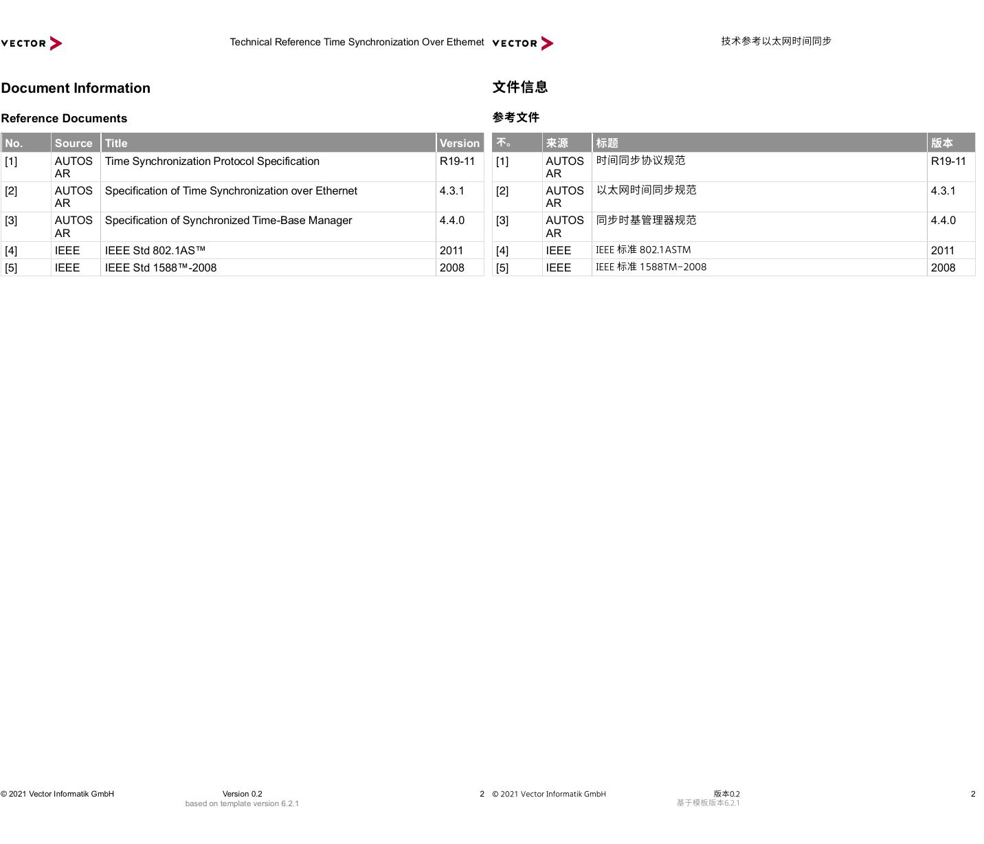
Technical Reference Time Synchronization Over Ethernet © 2021 Vector Informatik GmbH Version 0.2 2 based on template version 6.2.1 Document Information Reference Documents No. Source Title Version [1] AUTOSAR Time Synchronization Protocol Specification R19-11 [2] AUTOSAR Specification of Time Synchronization over Ethernet 4.3.1 [3] AUTOSAR Specification of Synchronized Time-Base Manager 4.4.0 [4] IEEE IEEE Std 802.1AS™ 2011 [5] IEEE IEEE Std 1588™-2008 2008 2 [1] AUTOSAR R19-11 [2] AUTOSAR 4.3.1 [3] AUTOSAR 4.4.0 [4] IEEE 2011 [5] IEEE 2008 技术参考以太网时间同步文件信息参考文件不。来源标题版本时间同步协议规范以太网时间同步规范同步时基管理器规范IEEE 标准 802.1ASTMIEEE 标准 1588TM-2008© 2021 Vector Informatik GmbH版本0.2基于模板版本6.2.1�
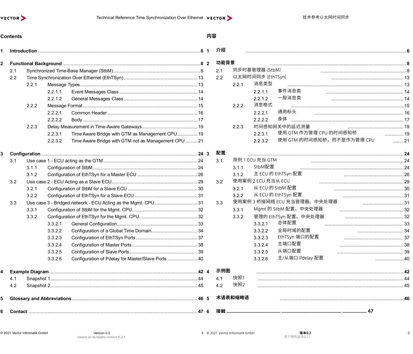
Technical Reference Time Synchronization Over Ethernet © 2021 Vector Informatik GmbH Version 0.2 3 based on template version 6.2.1 Contents 1 Introduction ....................................................................................................................... 6 2 Functional Background ..................................................................................................... 8 2.1 Synchronized Time-Base Manager (StbM) ................................................................ 8 2.2 Time Synchronization Over Ethernet (EthTSyn) ...................................................... 13 2.2.1 Message Types ...................................................................................... 13 2.2.1.1 Event Messages Class ......................................................... 14 2.2.1.2 General Messages Class ...................................................... 14 2.2.2 Message Format .................................................................................... 15 2.2.2.1 Common Header .................................................................. 16 2.2.2.2 Body .................................................................................... 17 2.2.3 Delay Measurement in Time-Aware Gateways......................................... 19 2.2.3.1 Time Aware Bridge with GTM as Management CPU ............... 19 2.2.3.2 Time Aware Bridge with GTM not as Management CPU ......... 21 3 Configuration ................................................................................................................... 24 3.1 Use case 1 - ECU acting as the GTM ..................................................................... 24 3.1.1 Configuration of StbM ............................................................................. 24 3.1.2 Configuration of EthTSyn for a Master ECU ............................................ 26 3.2 Use case 2 - ECU Acting as a Slave ECU ............................................................... 29 3.2.1 Configuration of StbM for a Slave ECU ................................................... 30 3.2.2 Configuration of EthTSyn for a Slave ECU .............................................. 31 3.3 Use case 3 - Bridged network - ECU Acting as the Mgmt. CPU ............................... 31 3.3.1 Configuration of StbM for the Mgmt. CPU ................................................ 32 3.3.2 Configuration of EthTSyn for the Mgmt. CPU........................................... 32 3.3.2.1 General Configuration ........................................................... 33 3.3.2.2 Configuration of a Global Time Domain.................................. 34 3.3.2.3 Configuration of EthTSyn Ports ............................................. 37 3.3.2.4 Configuration of Master Ports ................................................ 38 3.3.2.5 Configuration of Slave Ports .................................................. 39 3.3.2.6 Configuration of Pdelay for Master/Slave Ports ...................... 40 4 Example Diagram ............................................................................................................. 42 4.1 Snapshot 1 ............................................................................................................ 44 4.2 Snapshot 2 ............................................................................................................ 45 5 Glossary and Abbreviations ............................................................................................ 46 6 Contact ............................................................................................................................ 47 3 1 ...................................................................................................................... 6 2 .................................................................................................... 8 2.1 ............................................................... 8 2.2 ..................................................... 13 2.2.1 ..................................................................................... 13 2.2.1.1 ......................................................... 14 2.2.1.2 ..................................................... 14 2.2.2 ................................................................................... 15 2.2.2.1 ................................................................. 16 2.2.2.2 ................................................................................... 17 2.2.3 ......................................... 19 2.2.3.1 .............. 19 2.2.3.2 ........ 21 3 .................................................................................................................. 24 3.1 .................................................................... 24 3.1.1 ............................................................................ 24 3.1.2 ............................................ 26 3.2 .............................................................. 29 3.2.1 ................................................... 30 3.2.2 ............................................. 31 3.3 .............................. 31 3.3.1 ............................................... 32 3.3.2 ........................................... 32 3.3.2.1 .......................................................... 33 3.3.2.2 .................................. 34 3.3.2.3 ............................................ 37 3.3.2.4 ............................................... 38 3.3.2.5 ................................................. 39 3.3.2.6 ..................... 40 4 ............................................................................................................ 42 4.1 ........................................................................................................... 44 4.2 ........................................................................................................... 45 5 ........................................................................................... 46 6 技术参考以太网时间同步内容介绍功能背景同步时基管理器 (StbM)以太网时间同步 (EthTSyn)消息类型事件消息类一般消息类消息格式通用标头身体时间感知网关中的延迟测量使用 GTM 作为管理 CPU 的时间感知桥使用 GTM 的时间感知桥,而不是作为管理 CPU配置用例 1 ECU 充当 GTMStbM配置主 ECU 的 EthTSyn 配置使用案例 2 ECU 充当从 ECU从 ECU 的 StbM 配置从 ECU 的 EthTSyn 配置使用案例 3 桥接网络 ECU 充当管理器。中央处理器Mgmt 的 StbM 配置。中央处理器管理的 EthTSyn 配置。中央处理器总体配置全局时域的配置EthTSyn 端口的配置主端口配置从端口配置主/从端口 Pdelay 配置示例图快照1快照2术语表和缩略语接触 ................................................. ...................................................... ...................... 47© 2021 Vector Informatik GmbH版本0.2基于模板版本6.2.1�
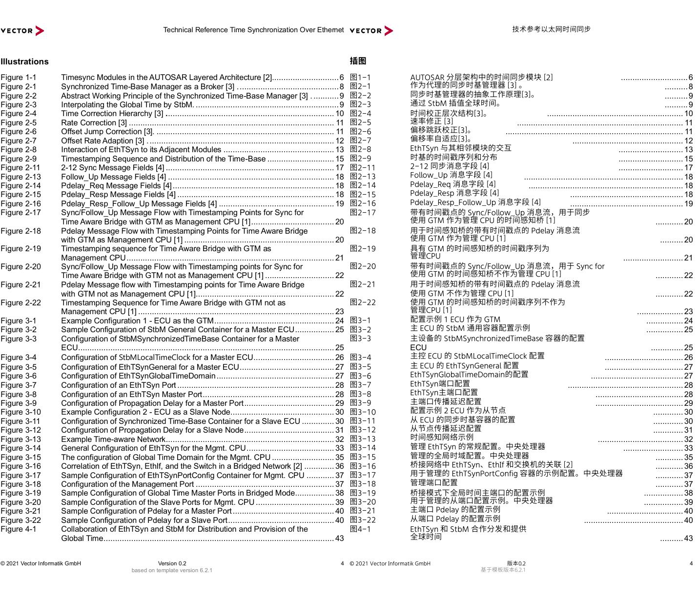
Technical Reference Time Synchronization Over Ethernet © 2021 Vector Informatik GmbH Version 0.2 4 based on template version 6.2.1 Illustrations Figure 1-1 Timesync Modules in the AUTOSAR Layered Architecture [2]............................. 6 Figure 2-1 Synchronized Time-Base Manager as a Broker [3] . ........................................... 8 Figure 2-2 Abstract Working Principle of the Synchronized Time-Base Manager [3] . ........... 9 Figure 2-3 Interpolating the Global Time by StbM. .............................................................. 9 Figure 2-4 Time Correction Hierarchy [3] . ........................................................................ 10 Figure 2-5 Rate Correction [3] ......................................................................................... 11 Figure 2-6 Offset Jump Correction [3]. ............................................................................. 11 Figure 2-7 Offset Rate Adaption [3] . ................................................................................ 12 Figure 2-8 Interaction of EthTSyn to its Adjacent Modules ................................................ 13 Figure 2-9 Timestamping Sequence and Distribution of the Time-Base ............................. 15 Figure 2-11 2-12 Sync Message Fields [4] ......................................................................... 17 Figure 2-13 Follow_Up Message Fields [4] ........................................................................ 18 Figure 2-14 Pdelay_Req Message Fields [4] ...................................................................... 18 Figure 2-15 Pdelay_Resp Message Fields [4] .................................................................... 18 Figure 2-16 Pdelay_Resp_Follow_Up Message Fields [4] .................................................. 19 Figure 2-17 Sync/Follow_Up Message Flow with Timestamping Points for Sync for Time Aware Bridge with GTM as Management CPU [1] .................................... 20 Figure 2-18 Pdelay Message Flow with Timestamping Points for Time Aware Bridge with GTM as Management CPU [1] ................................................................. 20 Figure 2-19 Timestamping sequence for Time Aware Bridge with GTM as Management CPU .......................................................................................... 21 Figure 2-20 Sync/Follow_Up Message Flow with Timestamping points for Sync for Time Aware Bridge with GTM not as Management CPU [1] .............................. 22 Figure 2-21 Pdelay Message flow with Timestamping points for Time Aware Bridge with GTM not as Management CPU [1]............................................................ 22 Figure 2-22 Timestamping Sequence for Time Aware Bridge with GTM not as Management CPU [1] ..................................................................................... 23 Figure 3-1 Example Configuration 1 - ECU as the GTM .................................................... 24 Figure 3-2 Sample Configuration of StbM General Container for a Master ECU ................. 25 Figure 3-3 Configuration of StbMSynchronizedTimeBase Container for a Master ECU ............................................................................................................... 25 Figure 3-4 Configuration of StbMLocalTimeClock for a Master ECU ................................... 26 Figure 3-5 Configuration of EthTSynGeneral for a Master ECU ......................................... 27 Figure 3-6 Configuration of EthTSynGlobalTimeDomain ................................................... 27 Figure 3-7 Configuration of an EthTSyn Port .................................................................... 28 Figure 3-8 Configuration of an EthTSyn Master Port ......................................................... 28 Figure 3-9 Configuration of Propagation Delay for a Master Port ....................................... 29 Figure 3-10 Example Configuration 2 - ECU as a Slave Node ............................................. 30 Figure 3-11 Configuration of Synchronized Time-Base Container for a Slave ECU .............. 30 Figure 3-12 Configuration of Propagation Delay for a Slave Node ....................................... 31 Figure 3-13 Example Time-aware Network ......................................................................... 32 Figure 3-14 General Configuration of EthTSyn for the Mgmt. CPU ...................................... 33 Figure 3-15 The configuration of Global Time Domain for the Mgmt. CPU ........................... 35 Figure 3-16 Correlation of EthTSyn, EthIf, and the Switch in a Bridged Network [2] ............. 36 Figure 3-17 Sample Configuration of EthTSynPortConfig Container for Mgmt. CPU ............ 37 Figure 3-18 Configuration of the Management Port ............................................................ 37 Figure 3-19 Sample Configuration of Global Time Master Ports in Bridged Mode................. 38 Figure 3-20 Sample Configuration of the Slave Ports for Mgmt. CPU .................................. 39 Figure 3-21 Sample Configuration of Pdelay for a Master Port ............................................ 40 Figure 3-22 Sample Configuration of Pdelay for a Slave Port .............................................. 40 Figure 4-1 Collaboration of EthTSyn and StbM for Distribution and Provision of the Global Time .................................................................................................... 43 4 ............................. 6 .......... 8 .......... 9 .......... 9 ........................................................... 10 ........................................................................ 11 ............................................................................. 11 ................................................ 12 ............................ 13 ............................ 15 ............................ 17 ..................................................................... 18 ................................................................... 18 ................................................. 18 ................................................. 19 ............ 20 .......... 20 .......................... 21 ............ 22 ............ 22 .................... 23 ................ 24 ................ 25 ECU.............. 25 .................................. 26 .................................. 27 ........................................ 27 .................................................. 28 ...................................... 28 ...................................... 29 ............. 30 ............. 30 ............. 31 ..................................... 32 .......................... 33 ............ 35 ............ 36 ............ 37 ............ 37 ................. 38 ................. 39 ................................. 40 ........................................... 40 .......... 43 技术参考以太网时间同步插图图1-1AUTOSAR 分层架构中的时间同步模块 [2]作为代理的同步时基管理器 [3] 。图2-1同步时基管理器的抽象工作原理[3]。图2-2通过 StbM 插值全球时间。图2-3图2-4时间校正层次结构[3]。速率修正 [3]图2-5偏移跳跃校正[3]。图2-6偏移率自适应[3]。图2-7EthTSyn 与其相邻模块的交互图2-8时基的时间戳序列和分布图2-92-12 同步消息字段 [4]图2-11Follow_Up 消息字段 [4]图2-13Pdelay_Req 消息字段 [4]图2-14Pdelay_Resp 消息字段 [4]图2-15Pdelay_Resp_Follow_Up 消息字段 [4]图2-16图2-17带有时间戳点的 Sync/Follow_Up 消息流,用于同步使用 GTM 作为管理 CPU 的时间感知桥 [1]图2-18用于时间感知桥的带有时间戳点的 Pdelay 消息流使用 GTM 作为管理 CPU [1]图2-19具有 GTM 的时间感知桥的时间戳序列为管理CPU图2-20带有时间戳点的 Sync/Follow_Up 消息流,用于 Sync for使用 GTM 的时间感知桥不作为管理 CPU [1]图2-21用于时间感知桥的带有时间戳点的 Pdelay 消息流使用 GTM 不作为管理 CPU [1]图2-22使用 GTM 的时间感知桥的时间戳序列不作为管理CPU [1]配置示例 1 ECU 作为 GTM图3-1主 ECU 的 StbM 通用容器配置示例图3-2图3-3主设备的 StbMSynchronizedTimeBase 容器的配置主控 ECU 的 StbMLocalTimeClock 配置图3-4主 ECU 的 EthTSynGeneral 配置图3-5EthTSynGlobalTimeDomain的配置图3-6EthTSyn端口配置图3-7EthTSyn主端口配置图3-8主端口传播延迟配置图3-9配置示例 2 ECU 作为从节点图3-10从 ECU 的同步时基容器的配置图3-11从节点传播延迟配置图3-12时间感知网络示例图3-13管理 EthTSyn 的常规配置。中央处理器图3-14管理的全局时域配置。中央处理器图3-15桥接网络中 EthTSyn、EthIf 和交换机的关联 [2]图3-16用于管理的 EthTSynPortConfig 容器的示例配置。中央处理器图3-17管理端口配置图3-18图3-19桥接模式下全局时间主端口的配置示例用于管理的从端口配置示例。中央处理器图3-20主端口 Pdelay 的配置示例图3-21从端口 Pdelay 的配置示例图3-22图4-1EthTSyn 和 StbM 合作分发和提供全球时间© 2021 Vector Informatik GmbH版本0.2基于模板版本6.2.1�
Technical Reference Time Synchronization Over Ethernet © 2021 Vector Informatik GmbH Version 0.2 5 based on template version 6.2.1 Figure 4-2 Snapshot of StbM and EthTSyn Collaboration in the GTM ................................ 44 Figure 4-3 Snapshot of StbM and EthTSyn Collaboration in the Slave Node ...................... 45 5 ..................... 44 ..................... 45 技术参考以太网时间同步GTM 中 StbM 和 EthTSyn 合作的快照图4-2StbM 和 EthTSyn 在从节点中协作的快照图4-3© 2021 Vector Informatik GmbH版本0.2基于模板版本6.2.1�
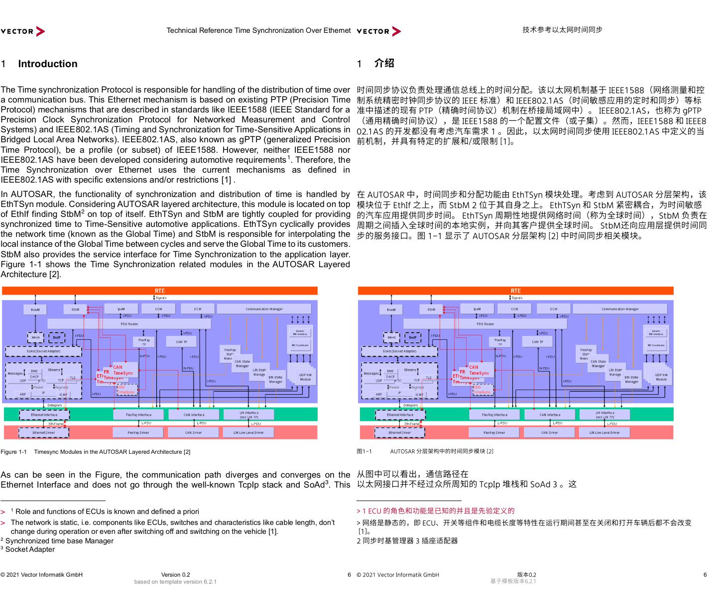
Technical Reference Time Synchronization Over Ethernet © 2021 Vector Informatik GmbH Version 0.2 6 based on template version 6.2.1 1 Introduction The Time synchronization Protocol is responsible for handling of the distribution of time over a communication bus. This Ethernet mechanism is based on existing PTP (Precision Time Protocol) mechanisms that are described in standards like IEEE1588 (IEEE Standard for a Precision Clock Synchronization Protocol for Networked Measurement and Control Systems) and IEEE802.1AS (Timing and Synchronization for Time-Sensitive Applications in Bridged Local Area Networks). IEEE802.1AS, also known as gPTP (generalized Precision Time Protocol), be a profile (or subset) of IEEE1588. However, neither IEEE1588 nor IEEE802.1AS have been developed considering automotive requirements1. Therefore, the Time Synchronization over Ethernet uses the current mechanisms as defined in IEEE802.1AS with specific extensions and/or restrictions [1] . In AUTOSAR, the functionality of synchronization and distribution of time is handled by EthTSyn module. Considering AUTOSAR layered architecture, this module is located on top of EthIf finding StbM2 on top of itself. EthTSyn and StbM are tightly coupled for providing synchronized time to Time-Sensitive automotive applications. EthTSyn cyclically provides the network time (known as the Global Time) and StbM is responsible for interpolating the local instance of the Global Time between cycles and serve the Global Time to its customers. StbM also provides the service interface for Time Synchronization to the application layer. Figure 1-1 shows the Time Synchronization related modules in the AUTOSAR Layered Architecture [2]. Figure 1-1 Timesync Modules in the AUTOSAR Layered Architecture [2] As can be seen in the Figure, the communication path diverges and converges on the Ethernet Interface and does not go through the well-known TcpIp stack and SoAd3. This > 1 Role and functions of ECUs is known and defined a priori > The network is static, i.e. components like ECUs, switches and characteristics like cable length, don’t change during operation or even after switching off and switching on the vehicle [1]. 2 Synchronized time base Manager 3 Socket Adapter 6 1 技术参考以太网时间同步介绍时间同步协议负责处理通信总线上的时间分配。该以太网机制基于 IEEE1588(网络测量和控制系统精密时钟同步协议的 IEEE 标准)和 IEEE802.1AS(时间敏感应用的定时和同步)等标准中描述的现有 PTP(精确时间协议)机制在桥接局域网中)。 IEEE802.1AS,也称为 gPTP(通用精确时间协议),是 IEEE1588 的一个配置文件(或子集)。然而,IEEE1588 和 IEEE802.1AS 的开发都没有考虑汽车需求 1 。因此,以太网时间同步使用 IEEE802.1AS 中定义的当前机制,并具有特定的扩展和/或限制 [1]。在 AUTOSAR 中,时间同步和分配功能由 EthTSyn 模块处理。考虑到 AUTOSAR 分层架构,该模块位于 EthIf 之上,而 StbM 2 位于其自身之上。 EthTSyn 和 StbM 紧密耦合,为时间敏感的汽车应用提供同步时间。 EthTSyn 周期性地提供网络时间(称为全球时间),StbM 负责在周期之间插入全球时间的本地实例,并向其客户提供全球时间。 StbM还向应用层提供时间同步的服务接口。图 1-1 显示了 AUTOSAR 分层架构 [2] 中时间同步相关模块。图1-1AUTOSAR 分层架构中的时间同步模块 [2]从图中可以看出,通信路径在以太网接口并不经过众所周知的 TcpIp 堆栈和 SoAd 3 。这> 1 ECU 的角色和功能是已知的并且是先验定义的> 网络是静态的,即 ECU、开关等组件和电缆长度等特性在运行期间甚至在关闭和打开车辆后都不会改变 [1]。2 同步时基管理器 3 插座适配器© 2021 Vector Informatik GmbH版本0.2基于模板版本6.2.1�
Technical Reference Time Synchronization Over Ethernet © 2021 Vector Informatik GmbH Version 0.2 7 based on template version 6.2.1 means that the time synchronization protocol is Ethernet frame based1 and network segmentation through IP layer is not considered. However, unlike IEEE 802.1AS, network segmentation is possible at the link layer with limitations2. Therefore, PTP frames can have VLAN Tag [2]. Further technical details will be discussed in the next chapters. Nodes of a time-aware network are identified by their role being a Master or a Slave. These roles and functions of ECUs are known and defined a priori. Each Time Domain only has one Global Master node known as GTM3. Although the role of a GTM can be delegated to other nodes of the network, this happens only in case of failure in the GTM and is given back after the failure is resolved. Therefore, dynamic mechanisms like determining the Global Time Master (denoted as grandmaster in IEEE802.1AS) by the best master clock algorithm (BMCA) during operation are not required [1]. As previously mentioned, EthTSyn and StbM are functionally tightly coupled. Due to this, in this document, significant functional points of these modules are discussed, and necessary configuration hints will be explained. The configuration examples will consider an abstraction of typical time-aware network use-cases and are demonstrated in Vector’s DaVinci Configurator tool. The rest of the document is organized as follows: Section 2 briefly describes functional overview of two modules EthTSyn and StbM as well as their practical semantics applicable to AUTOSAR and Automotive Embedded Systems. Section 3 presents the associated configuration parameters as well as the relevant numerical values for our example scenario. Finally, section 4 will present an example diagram depicting the functional concept utterly. 1 Commonly known as PTP frames 2 For further information, please refer tosee [2] . 3 Global Time Master 7 技术参考以太网时间同步意味着时间同步协议是基于以太网帧1并且不考虑通过IP层的网络分段。然而,与 IEEE 802.1AS 不同,网络分段可以在链路层进行,但有局限性2。因此,PTP帧可以带有VLAN标签[2]。进一步的技术细节将在接下来的章节中讨论。时间感知网络的节点通过其角色(主节点或从节点)来标识。 ECU 的这些角色和功能是已知的并且是预先定义的。每个时域只有一个全局主节点,称为 GTM3。虽然 GTM 的角色可以委托给网络的其他节点,但这仅在 GTM 发生故障的情况下发生,并在故障解决后恢复。因此,不需要在运行期间通过最佳主时钟算法(BMCA)确定全局时间主控(在 IEEE802.1AS 中表示为 Grandmaster)等动态机制[1]。如前所述,EthTSyn 和 StbM 在功能上紧密耦合。因此,在本文档中,讨论了这些模块的重要功能点,并解释了必要的配置提示。配置示例将考虑典型时间感知网络用例的抽象,并在 Vector 的 DaVinci 配置器工具中进行演示。该文件的其余部分组织如下:第 2 节简要描述了 EthTSyn 和 StbM 两个模块的功能概述以及它们适用于 AUTOSAR 和汽车嵌入式系统的实用语义。第 3 节介绍了示例场景的相关配置参数以及相关数值。最后,第 4 节将提供一个完整描述功能概念的示例图。1 俗称PTP帧 2 欲了解更多信息,请参阅[2]。3 全球时间大师© 2021 Vector Informatik GmbH版本0.2基于模板版本6.2.1�
Technical Reference Time Synchronization Over Ethernet © 2021 Vector Informatik GmbH Version 0.2 8 based on template version 6.2.1 2 Functional Background In this chapter, a preliminary foundation of Time Synchronization Over Ethernet will be reviewed. As discussed in the previous section, in automotive use-cases, as specified by AUTOSAR, synchronization of time is accomplished via two main functional roles, Global time provider and synchronized time broker. These roles are assigned to EthTSyn and StbM modules respectively. Accordingly, in the following subsections, the main tasks of these two modules are to be introduced. 2.1 Synchronized Time-Base Manager (StbM) Figure 1 illustrates how the Synchronized Time-Base Manager interacts with other modules. Figure 2-1 Synchronized Time-Base Manager as a Broker [3] . As seen in the figure, StbM is bus independent. The Synchronized Time-Base Manager itself does not provide any time agreement protocols to synchronize its local Time-Bases to Time-Bases on other nodes. It interacts with the TSyn modules of the BSW to achieve such synchronization. With the information retrieved from the provider modules, the Synchronized Time-Base Manager can synchronize its Time-Bases to Time-Bases on other nodes [3]. StbM maintains a local instance of the Global time and serves it to its so-called customers. Three types of customers may be distinguished: Triggered customer, Active customer, and Notification customer (for further information about the details, please refer to [3]). Thus, the StbM acts as Time-Base broker by offering the customers access to the Synchronized Time-Bases. In general, distribution of time is cyclic (e.g. every 125ms) by EthTSyn. Due to this, StbM must provide access to the Global Time during the time between two consecutive updates of the time. StbM provides the time to its customers through interpolating the local instance of the Global Time whenever an access is required. This is realized by using a hardware reference clock as well as a software counter. This combination forms Virtual Local Time. The schematic of maintaining the local instance of the global time is illustrated in the following figure [3]. 8 2 技术参考以太网时间同步功能背景本章将回顾以太网时间同步的初步基础。如上一节所述,在汽车用例中,按照 AUTOSAR 的规定,时间同步是通过两个主要功能角色完成的:全局时间提供者和同步时间代理。这些角色分别分配给 EthTSyn 和 StbM 模块。因此,在下面的小节中将介绍这两个模块的主要任务。2.1 同步时基管理器(StbM)图 1 说明了同步时基管理器如何与其他模块交互。图 2-1 作为代理的同步时基管理器 [3]。如图所示,StbM 与总线无关。同步时基管理器本身不提供任何时间协议协议来将其本地时基同步到其他节点上的时基。它与 BSW 的 TSyn 模块交互以实现此类同步。利用从提供者模块检索的信息,同步时基管理器可以将其时基同步到其他节点上的时基[3]。StbM 维护全球时间的本地实例并将其提供给所谓的客户。可以区分三种类型的客户:触发型客户、活跃型客户和通知型客户(详细信息请参阅[3])。因此,StbM 通过为客户提供对同步时基的访问来充当时基代理。一般来说,EthTSyn 的时间分配是循环的(例如每 125 毫秒)。因此,StbM 必须在两次连续更新时间之间的时间内提供对全球时间的访问。每当需要访问时,StbM 通过插入全球时间的本地实例为其客户提供时间。这是通过使用硬件参考时钟和软件计数器来实现的。这种组合形成了虚拟本地时间。维护全局时间本地实例的示意图如下图[3]所示。© 2021 Vector Informatik GmbH版本0.2基于模板版本6.2.1�


 V2版本原理图(Capacitive-Fingerprint-Reader-Schematic_V2).pdf
 摄像头工作原理.doc
 VL53L0X简要说明(En.FLVL53L00216).pdf
 原理图(DVK720-Schematic).pdf
 原理图(Pico-Clock-Green-Schdoc).pdf
 原理图(RS485-CAN-HAT-B-schematic).pdf
 File:SIM7500_SIM7600_SIM7800 Series_SSL_Application Note_V2.00.pdf
 ADS1263(Ads1262).pdf
 原理图(Open429Z-D-Schematic).pdf
 用户手册(Capacitive_Fingerprint_Reader_User_Manual_CN).pdf
 CY7C68013A(英文版)(CY7C68013A).pdf
 TechnicalReference_Dem.pdf