logo资料库

DTU说明(RM0001E_mxchipWNet_DTU_V4_1).pdf

第1页 / 共54页
第2页 / 共54页
第3页 / 共54页
第4页 / 共54页
第5页 / 共54页
第6页 / 共54页
第7页 / 共54页
第8页 / 共54页
资料共54页,剩余部分请下载后查看
1 Introduction
1.1 LED Functions Controlled by Firmware
1.2 Pin Definition Under mxchipWNetTM-DTU
1.2.1 EMW3280, EMW3160 and EMW3162
1.2.2 EMW3161
1.3 Function Description of Each Pin
1.4 Typical hardware connections
2 Firmware Working Modes and Switching
2.1 Working Flowchart
2.2 Working Modes
2.3 Working Mode after Power On
2.4 Switching between Working Modes
2.5 Default Settings
3 Direct Transmission Mode
3.1 QUICK START
3.1.1 Hardware Connection
3.1.2 Connect to module using Wi-Fi
3.1.3 Data transmission between serial port and Wi-Fi
3.2 Internal mechanism of Direct Transmission Mode
3.2.1 Serial Port=>Wireless Network
3.2.2 Wireless Network => Serial Port
3.3 Half Duplex Mode (HDC mode)
4 EMSP Command Mode
4.1 QUICK START
4.1.1 Hardware Connection
4.1.2 Send EMSP command using EMW Tool Box
4.2 EMSP Command Specification
4.3 Command Description
4.3.1 Static Configuration Commands
EMSP_CMD_GET_CONFIG (COMMAND ID 0002)
EMSP_CMD_SET_CONFIG (COMMAND ID 0003)
EMSP_CMD_SET_DNS (COMMAND ID 0052)
EMSP_CMD_GET_DNS (COMMAND ID 0053)
EMSP_CMD_SET_EXTRA_SSID (COMMAND ID 0064)
EMSP_CMD_GET_EXTRA_SSID (COMMAND ID 0065)
EMSP_CMD_SET_EXTRA_SOCKET (COMMAND ID 0069)
EMSP_CMD_GET_EXTRA_SSID (COMMAND ID 006A)
EMSP_CMD_SET_KEEPALIVE (COMMAND ID 006B)
EMSP_CMD_GET_KEEPALIVE (COMMAND ID 006C)
EMSP_CMD_SET_PS_MODE (COMMAND ID 0063)
EMSP_CMD_GET_PS_MODE (COMMAND ID 0066)
EMSP_CMD_SET_DUAL_UAP (COMMAND ID 0067)
EMSP_CMD_GET_DUAL_UAP (COMMAND ID 0068)
EMSP_CMD_GET_UART_MODE (COMMAND ID 0062)
EMSP_CMD_SET_UART_MODE (COMMAND ID 0061)
EMSP_CMD_GET_NAME (COMMAND ID 0046)
EMSP_CMD_SET_NAME (COMMAND ID 0047)
EMSP_CMD_GET_VER (COMMAND ID 006F)
EMSP_CMD_GET_MAC_ADDR (COMMAND ID 000C)
4.3.2 Dynamic Control Commands
EMSP_CMD_RESET (COMMAND ID 0001)
EMSP_CMD_START (COMMAND ID 0005)
EMSP_CMD_GET_STATUS (COMMAND ID 0008)
EMSP_CMD_GET_IP (COMMAND ID 0040)
EMSP_CMD_OPEN_SOCKET (COMMAND ID 0045)
EMSP_CMD_CLOSE_SOCKET (COMMAND ID 0044)
EMSP_CMD_WIFI_STOP (COMMAND ID 004A)
EMSP_CMD_WIFI_CONNECT (COMMAND ID 004B)
EMSP_CMD_SCAN_AP (COMMAND ID 0004)
EMSP_CMD_SEND_DATA (COMMAND ID 0006)
EMSP_CMD_RECV_DATA (COMMAND ID 0007)
5 Methods of Configuration
5.1 Build-in Web Pages Method
5.2 EMSP Commands Method
5.3 Near-Field-Communication Method
5.4 Wi-Fi Protected Setup (WPS)
5.5 Easy Link Method
6 Low power modes
7 Network Services
7.1 Use mDNS (Bonjour) Service to find module in local network
7.1.1 Bonjour definition:
7.1.2 Demonstration:
7.2 Use UDP broadcast to find modules in local network
7.3 DHCP Server
8 Sales Information
9 Technical Support
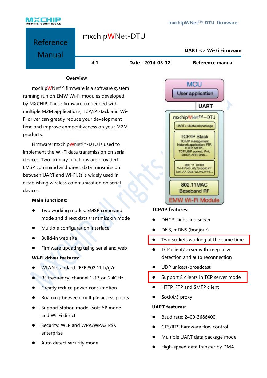
Reference Manual mxchipWNetTM-DTU firmware mxchipWNet-DTU 4.1 Date:2014-03-12 Reference manual UART <> Wi-Fi Firmware Overview mxchipWNetTM firmware is a software system running run on EMW Wi-Fi modules developed by MXCHIP. These firmware embedded with multiple M2M applications, TCP/IP stack and Wi- Fi driver can greatly reduce your development time and improve competitiveness on your M2M products. Firmware: mxchipWNetTM-DTU is used to implement the Wi-Fi data transmission on serial devices. Two primary functions are provided: EMSP command and direct data transmission between UART and Wi-Fi. It is widely used in establishing wireless communication on serial devices. Main functions:  Two working modes: EMSP command TCP/IP features: mode and direct data transmission mode  Multiple configuration interface  Build-in web site  Firmware updating using serial and web Wi-Fi driver features:  DHCP client and server  DNS, mDNS (bonjour)  Two sockets working at the same time  TCP client/server with keep-alive detection and auto reconnection  WLAN standard: IEEE 802.11 b/g/n  UDP unicast/broadcast  RF frequency: channel 1-13 on 2.4GHz  Support 8 clients in TCP server mode  Greatly reduce power consumption  HTTP, FTP and SMTP client  Roaming between multiple access points  Sock4/5 proxy  Support station mode,, soft AP mode UART features: and Wi-Fi direct  Security: WEP and WPA/WPA2 PSK enterprise  Auto detect security mode  Baud rate: 2400-3686400  CTS/RTS hardware flow control  Multiple UART data package mode  High-speed data transfer by DMA
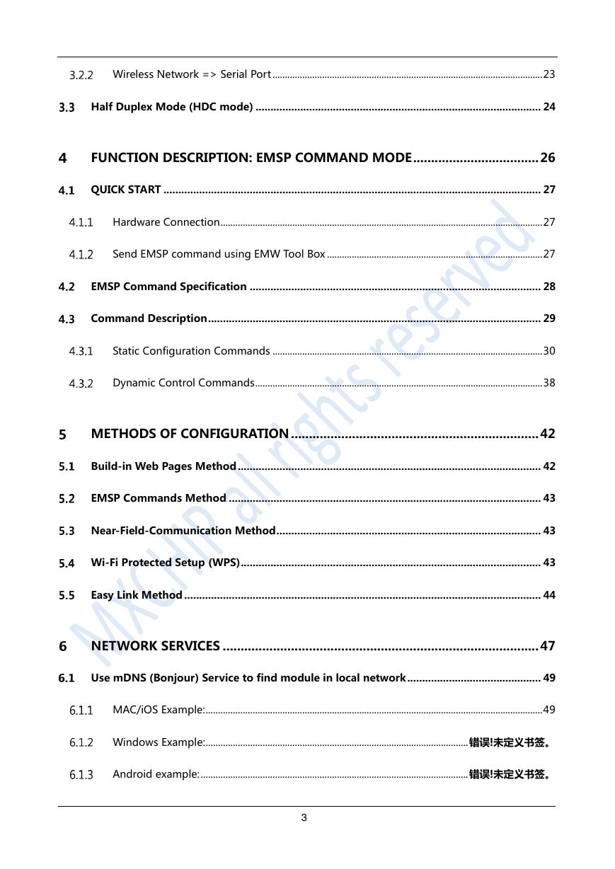
Contents INTRODUCTION .................................................................................................. 5 LED Functions Controlled by Firmware ...................................................................................... 5 Pin Definition Under mxchipWNetTM-DTU ................................................................................ 6 EMW3280, EMW3160 and EMW3162 ...................................................................................................... 6 EMW3161 ........................................................................................................................................................... 6 Function Description of Each Pin ................................................................................................ 7 Typical hardware connections ..................................................................................................... 9 FIRMWARE WORKING MODES AND SWITCHING ........................................ 11 Working Flowchart ...................................................................................................................... 11 Working Modes ........................................................................................................................... 12 Working Mode after Power On ................................................................................................. 12 Switching between Working Modes ......................................................................................... 13 Default Settings ........................................................................................................................... 14 FUNCTION DESCRIPTION: DIRECT TRANSMISSION MODE ........................ 15 QUICK START ............................................................................................................................... 15 Hardware Connection .................................................................................................................................. 15 Connect to module using Wi-Fi ............................................................................................................... 17 Data transmission between serial port and Wi-Fi ............................................................................. 18 Internal mechanism of Direct Transmission Mode ................................................................. 20 Serial Port=>Wireless Network................................................................................................................ 20 2
Wireless Network => Serial Port ............................................................................................................. 23 Half Duplex Mode (HDC mode) ................................................................................................ 24 FUNCTION DESCRIPTION: EMSP COMMAND MODE ................................... 26 QUICK START ............................................................................................................................... 27 Hardware Connection .................................................................................................................................. 27 Send EMSP command using EMW Tool Box ....................................................................................... 27 EMSP Command Specification .................................................................................................. 28 Command Description ................................................................................................................ 29 Static Configuration Commands ............................................................................................................. 30 Dynamic Control Commands .................................................................................................................... 38 METHODS OF CONFIGURATION ..................................................................... 42 Build-in Web Pages Method ...................................................................................................... 42 EMSP Commands Method ......................................................................................................... 43 Near-Field-Communication Method ......................................................................................... 43 Wi-Fi Protected Setup (WPS) ..................................................................................................... 43 Easy Link Method ........................................................................................................................ 44 NETWORK SERVICES ........................................................................................ 47 Use mDNS (Bonjour) Service to find module in local network ............................................. 49 MAC/iOS Example: ........................................................................................................................................ 49 Windows Example: .......................................................................................................... 错误!未定义书签。 Android example: ............................................................................................................ 错误!未定义书签。 3
Use UDP broadcast to find module in local network ............................................................. 51 DHCP Server ................................................................................................................................ 52 SALES INFORMATION ...................................................................................... 53 TECHNICAL SUPPORT ...................................................................................... 54 4
Introduction mxchipWNetTM firmware is a software system running run on EMW Wi-Fi modules developed by MXCHIP. These firmware embedded with multiple M2M applications, TCP/IP stack and Wi-Fi driver can greatly reduce your development time and improve competitiveness on your M2M products. One of the firmware: mxchipWNetTM-DTU is used to implement the Wi-Fi data transmission on serial devices. Two primary functions: EMSP command and direct data transmission between UART and Wi-Fi are provided. It is widely used in establishing wireless communication on serial devices. mxchipWNetTM-DTU can run on: EMW3280, EMW3161, and EMW3162. LEDs and pins on these module are defined to a specified function which is described in 1.1 and 1.2: LED Functions Controlled by Firmware D1 D2 D1 EMW3280 EMW3161 D2 D1 D2 D1 EMW3162 EMW3160 Name Function description LED function list D1 D2* On Off Flash On Off Firmware initialize successful Firmware uninitialized, or deep sleep mode Firmware update mode Wi-Fi connected, DHCP negotiate success Wi-Fi disconnected Keep Data transmission/WPS negotiating/EasyLink Flashing mode * D2 led is available on EMW3280, EMW3162 and EMW3160, and you can also connect an external led from pin 16. D2 is not existed on EMW3161 module, so you should connect an external LED from pin 36 on EMW3161. 5
Pin Definition Under mxchipWNetTM-DTU EMW3280, EMW3160 and EMW3162 EMW3280, EMW3160 and EMW3162 Pinouts Pins Pin Name Pins 1 2 3 4 5 6 7 8 9 10 11 12 13 14 15 NFC_SCL NFC_SDA NC NC WPS/Default (IN) NC NC NC NC NC EasyLink/Default (IN) NC NFC_INT LoPow(IN) * GND 16 17 18 19 20 21 22 23 24 25 26 27 28 29 30 Pin Name LED (OUT) BOOT(IN) nRESET(IN) IO1 NC nUART_RTS(OUT) nUART_CTS(IN) UART_TXD(OUT) UART_RXD(IN) VDD GND NC NC NC nWAKE_UP(IN) STATUS(IN) * LoPow function is only available on EMW316x modules. 6
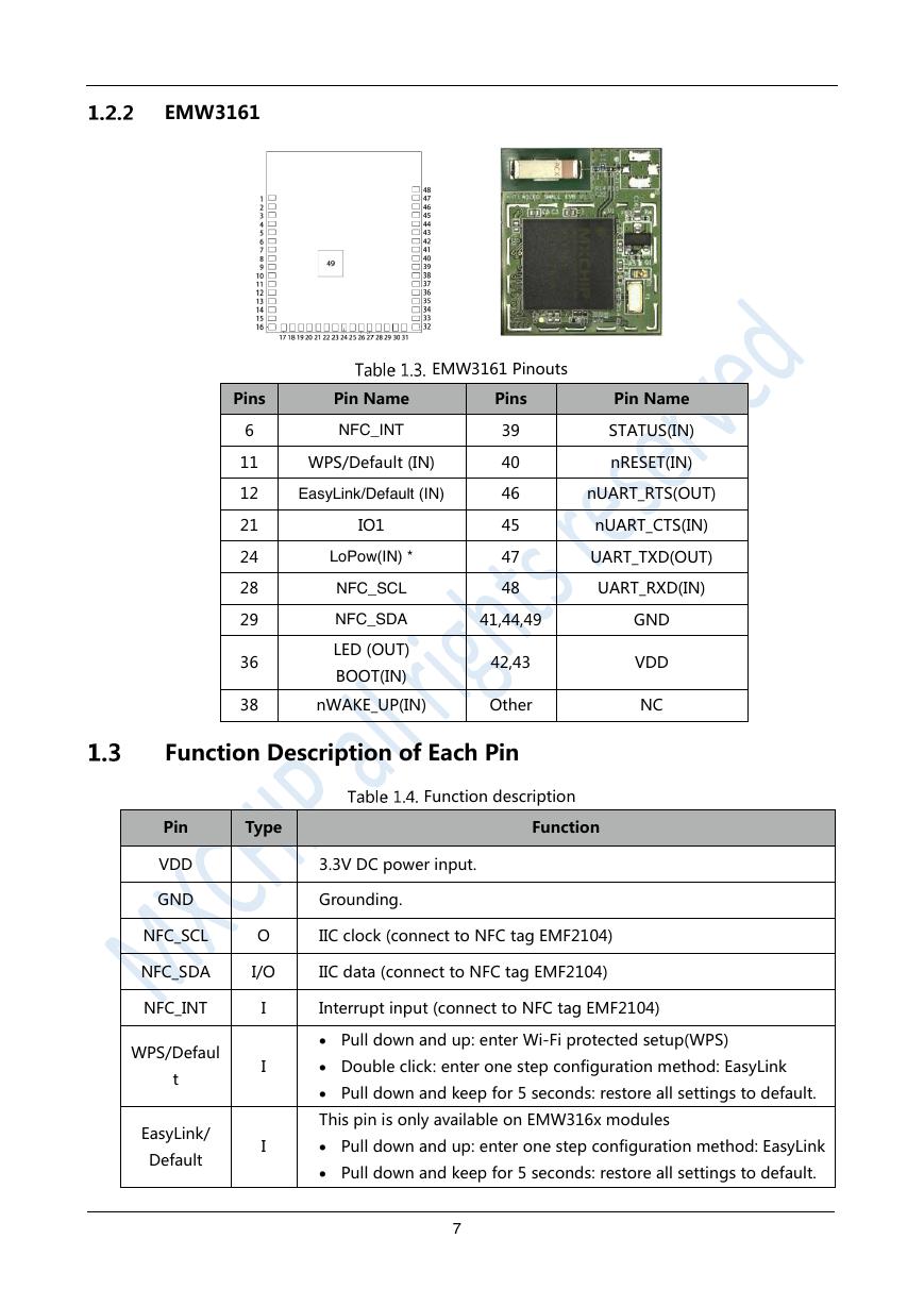
EMW3161 EMW3161 Pinouts Pins Pin Name Pins Pin Name 6 11 12 21 24 28 29 36 38 NFC_INT WPS/Default (IN) EasyLink/Default (IN) IO1 LoPow(IN) * NFC_SCL NFC_SDA LED (OUT) BOOT(IN) 39 40 46 45 47 48 41,44,49 42,43 nWAKE_UP(IN) Other STATUS(IN) nRESET(IN) nUART_RTS(OUT) nUART_CTS(IN) UART_TXD(OUT) UART_RXD(IN) GND VDD NC Function Description of Each Pin Pin Type VDD GND Function description Function 3.3V DC power input. Grounding. NFC_SCL O IIC clock (connect to NFC tag EMF2104) NFC_SDA I/O IIC data (connect to NFC tag EMF2104) NFC_INT WPS/Defaul t EasyLink/ Default I I I Interrupt input (connect to NFC tag EMF2104)  Pull down and up: enter Wi-Fi protected setup(WPS)  Double click: enter one step configuration method: EasyLink  Pull down and keep for 5 seconds: restore all settings to default. This pin is only available on EMW316x modules  Pull down and up: enter one step configuration method: EasyLink  Pull down and keep for 5 seconds: restore all settings to default. 7
Pin Type Function UART_RXD UART_TXD nUART_CTS5 nUART_RTS5 I O I O UART Data input. UART Data output. UART clear to send, active low. UART is ready to receive, active low. LoPow I  Pull up: Exit sleep mode Control the module’s MCU low power mode:  Pull down: Enter sleep mode Set the operation mode: STATUS I, PU1  Pull up: enter the direct data transmission mode  Pull down: enter the EMSP command mode Refer chapter 2 for details. Module enter deep sleep mode if the WAKE_UP pin is pulled low, WAKE_UP I, PU and wake up while the WAKE_UP pin is pulled high. Reset is needed to wake up EMW3161 from deep sleep mode. nRESET6 I, PU Pull down this pin for 1μs to reboot the module. BOOT signal is detected to enter the different working mode when LED/ BOOT module is powered on, Refer chapter 2 for details. I, PU  Pull up: Boot to normal working mode.  Pull down: Boot to special working modes (firmware update mode or test mode). O LED pin has the same function as led D2, This signal is active low. NC7 No function. (IO1 function is configured by firmware) FC mode: Used as a serial data frame controller in direct data I7 IO1 transmission mode.  Pull down: Module stores the received serial data in RAM  Pull up: Build up TCP/UDP package with the serial data in RAM HDC mode: Used as a Half-duplex Controller. Output a high level signal while sending a serial data, otherwise, O7 output a low level This function can also be used to wake up host before send any UART data. NC Undefined IOs. Leave them floating or grounding. 1. PU: The pin is at high level if no external signal is asserted. 2. PD: The pin is at low level if no external signal is asserted. 3. UART signals includes UART_TXD,UART_RXD,UART_RTS and UART_CTS。 4. Only VDD, GND UART_TXD and UART_RXD are needed in a simplest connection. 8
分享到:
收藏