Review
Frequency Selective Surfaces: A Review
Rana Sadaf Anwar 1, Lingfeng Mao 1 and Huansheng Ning 1,2,*
1
School of Computer and Communication Engineering, University of Science and Technology Beijing,
Beijing 100083, China; engr_rs@126.com (R.S.A.); lingfengmao@ustb.edu.cn (L.M.)
Beijing Engineering Research Center for Cyberspace Data Analysis and Applications, Beijing 100083, China
2
* Correspondence: ninghuansheng@ustb.edu.cn
Received: 6 August 2018; Accepted: 10 September 2018; Published: 18 September 2018
Abstract: The intent of this paper is to provide an overview of basic concepts, types, techniques,
and experimental studies of the current state-of-the-art Frequency Selective Surfaces (FSSs). FSS
is a periodic surface with identical two-dimensional arrays of elements arranged on a dielectric
substrate. An incoming plane wave will either be transmitted (passband) or reflected back (stopband),
completely or partially, depending on the nature of array element. This occurs when the frequency
of electromagnetic (EM) wave matches with the resonant frequency of the FSS elements. Therefore,
an FSS is capable of passing or blocking the EM waves of certain range of frequencies in the free
space; consequently, identified as spatial filters. Nowadays, FSSs have been studied comprehensively
and huge growth is perceived in the field of its designing and implementation for different practical
applications at frequency ranges of microwave to optical. In this review article, we illustrate the
recent researches on different categories of FSSs based on structure design, array element used,
and applications. We also focus on theoretical breakthroughs with fabrication techniques, experimental
verifications of design examples as well as prospects and challenges, especially in the microwave
regime. We emphasize their significant performance parameters, particularly focusing on how
advancement in this field could facilitate innovation in advanced electromagnetics.
Keywords: frequency selective surfaces; microwave frequency; spatial filters; electromagnetic waves;
periodic structures
1. Introduction
Metasurfaces are broadly named as planar metamaterials with subwavelength thickness and they
can be easily fabricated while using lithography and nano-printing techniques. Both metamaterials
and metasurfaces are rapidly growing research directions, and with their use, spatially varying EM or
optical responses can be achieved at will, with scattering phase, amplitude, and polarization. Through
a good selection of materials and design, the ultra-thin structure of MSs can considerably suppress
the detrimental and undesirable losses in the wave propagation direction. When considering the
polarization response, all metasurfaces can be categorized based on the operating principle of array
element, i-e their functionalities (frequency selective surfaces (FSS), high impedance surfaces, perfect
absorbers, reflecting surfaces, etc.).
According to the definition in [1], FSSs are metasurfaces that merely exhibit an electric response [2,3].
Since, in order to tailor the frequency selectiveness in transmission/reflection characteristics, only
electrical polarization may be sufficient. From the theory of antenna and microwave engineering, these
surfaces are made by planar and periodic arrays of metallic patches or strips with different shapes.
The patch is of negligible thickness as compared to the wavelength, although it is larger enough in
contrast to the metal’s skin depth. Consequently, such a structure can impeccably be estimated as a
minuscule thin array of perfect conducting resonant elements. This approximation is also applicable
Appl. Sci. 2018, 8, 1689; doi:10.3390/app8091689
www.mdpi.com/journal/applsci
applied sciences�# �&�!*-�0+��/ .�
Appl. Sci. 2018, 8, 1689
2 of 46
to the complementary FSSs structures i-e apertures. However, aperture-type FSSs face a limitation
when the area of the cavity/aperture becomes equal to the unit cell (a wire-mesh type) [2,3]. Square
and hexagonal wire-mesh unit cells have typically been used and are also termed as the capacitive
grid. The existence of the resonating size of array element causes the emergence of the side lobes in
the transmitted and reflected fields, which are the defining feature of FSSs. However, as compared
to the FSSs, the resonating element and unit cell of metasurface is relatively much smaller than the
wavelength and it helps to eliminate the grating lobes in the frequency response. Therefore, FSSs in
the terahertz domain are usually termed as metasurfaces [4].
Frequency selective surface (FSS) is a robustly studied topic of electromagnetic (EM) science,
which are two-dimensional periodic structures having planar metallic array elements (patch or
apertures) on a dielectric substrate, exhibiting transmission and reflection at certain resonant
frequency [2]. Depending on the array element design, an incoming plane wave will be either
transmitted or reflected, completely or partially. This happens when the frequency of the plane wave
matches the resonance frequency of the FSS elements. Therefore, an FSS can pass or block the EM
waves with certain frequencies in free space; so they are best identified as spatial filters.
Traditionally, the element size, shape, and periodicity of an FSS result in the resonance. FSSs
have extensively been investigated over six decades and a range of microwave and optical FSSs
structures have been evolved. In past, they were frequently used in reflector antennas [5], including
diplexers for quasi-optical microwave devices, resonant beam splitters, and antenna radomes [6,7].
Nowadays, FSSs have been employed in dichroic sub-reflectors [8], radio frequency identification
(RFID) [9], lenses antennas [10], and protection from electromagnetic interference [11]. Currently,
the most famous applications of FSSs are as antennas radomes and controlling radar cross-section (RCS).
Their performance is limited by the design complications, including the requirement of compact size
and insensitivity to the incidence angle, as well as polarization of EM wave, consequently stipulating to
improve their design features.
Traditional FSSs are narrow band and they do not provide adequate spatial filtering response.
Extensive research is going on to miniaturize the FSSs and improve the frequency response with broader
bandwidth (BW) at higher incidence angles and dual polarization. However, single layered FSS structures
have been proved inefficient due to unstable performance with the variation of EM wave incident
angle. To overcome the limitations of conventional single layer FSSs, multilayered FSSs have been
introduced, which offer additional flexibility of varying parameters for desired performance [12–17].
At present, FSSs based on fractal elements and miniaturized arrays (2.5 dimensional) are employed
for compactness [18–20]. Three-dimensional FSS structures and active FSSs have opened new doors in
microwave technology [21–24]. Additionally, embedded FSS (with inserted metallic rods and plates based
on stepped-impedance resonator) [25], integrated FSS and Electromagnetic band gap structures (EBG) [26],
and metamaterial FSSs [27,28] are the most recent advances implemented by microwave researchers.
In the past, dispersion properties of FSSs have been explored through approximate analytical
techniques, for example, which involve equivalent circuit method to analyze the transmission line
characteristics (By Quasi-static approximation). However, with the growth of more complex structures,
state-of-the-art numerical methods have been introduced, which use periodic boundary conditions
(PBC) allowing for the design analysis quite straightforward. Some of these include finite element
method (FEM), method of moments (MoM), finite difference time domain method (FDTD), and the
integral equation (boundary element) method (IEM/BEM) [29–35]. A well-known technique is
IEM/BEM used in combination with the MoM [36–39]. Various designs of FSSs and schemes to
examine their EM characteristics are well presented in [2,3].
Regardless of its importance, a detailed review of the various types FSS is undeniably in its
infancy. Particularly, an adequate demonstration of recent advancements in innovative FSS structures
that are linked with their frequency responses is required. In fact, a detailed overview of different
varieties of FSS from the standpoint of structure design, applications, and types of array elements,
is yet to emerge in the literature. Although a few review articles are available on FSSs or FSS based
�
Appl. Sci. 2018, 8, 1689
3 of 46
EM structures in broad frequency regimes [4,22,37,40–42], however, in this article we specifically
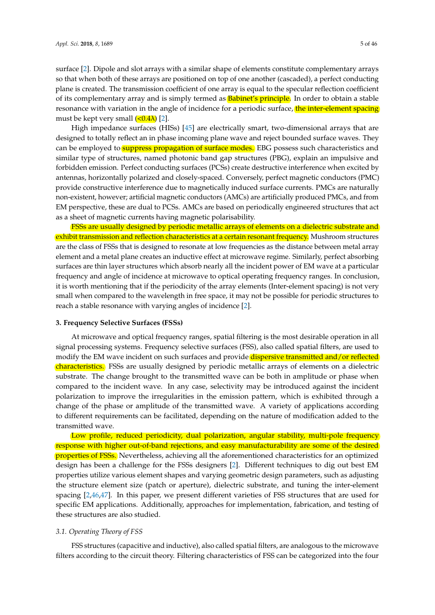
discuss the different kinds of FSSs operating at wavelengths in microwave range. Figure 1 depicts
a comparison of presented review with already available survey articles on FSSs. A more detailed
assessment of existing surveys in the literature is outlined in Table 1.
Figure 1. Comparison of the presented survey with previous review articles on FSSs.
As shown in Figure 1, the category 1 details theoretical reviews; for example, which discusses
a number of techniques to analyze FSSs as filters in the microwaves and optical ranges, and circuit
analytical review to underline the range validity of some model with their accuracies. In category 2,
while there exist some survey articles that target architectures of particular types of FSS, more focus
has been set in the literature toward the specific FSSs types (including metamaterials or metasurfaces
FSSs), FSS based antennas, and other FSS based EM structures.
On the other hand, researchers have less considered the survey on the different types of FSSs
that have recently evolved based on structural design, applications, and nature of array element used
and have taken this lack as for granted. Therefore, in this review paper, we provide an outlook of
skyrocketing research field of FSSs by assessing the progress during the past years primarily focusing
on categorizing the FSSs as mentioned above. The contributions of our effort in this review paper are
as follows.
(1) Through a careful study of the existing surveys on the FSSs, we identify the survey gap in
the existing reports, as briefed in Table 1, which accentuates the requirement to report most
up-to-date FSS types, especially in the microwave regime.
(2) Next, we present a classification of the FSSs, focus on the importance of their functionalities,
and categorize FSS on the basis of nature of array element used, structure design, and applications.
(3) This paper targets to link among their crucial theoretical, structure geometry, and significant
(4)
performance parameters.
For every functionality, the polarization state of the array elements and the physical mechanism
of their functions must be related to the frequency responses provided by FSSs. By knowing the
polarization characteristics of FSS periodic elements for a specific function, the implementation
of required FSS response in certain frequency band becomes straightforward and therefore,
we elaborate all types of FSS from this perspective.
(5) We illustrate an extensive survey of most recent researches on FSSs and also include their
fabrication techniques, experimental verifications of FSSs design. Prospects and challenges,
particularly in the microwave regime, are discussed focusing on how the innovation in this
field could smooth the progress in advanced electromagnetics. The article is organized, as
described below. In Section 2, we overview the concept of periodic surfaces with some of their
types. In Section 3, we introduce FSSs in detail and its theoretical background, along with some
�
Appl. Sci. 2018, 8, 1689
4 of 46
history and significant advances in recent years. In Section 4, we review different types of FSSs,
their related properties, implementation, and fabrication techniques. Section 5 presents future
challenges, trends, and potential applications of FSSs. In the last section, we provide concluding
remarks and a point of view about future research directions.
Table 1. Summary of focused topics of frequency selective surfaces (FSSs) covered by existing surveys.
Focused Topics
Theoretical Analysis
Evolution of FSS
FSS based EM structures
Individual type of FSSs
2. Periodic Structures
Description
•
•
FSS circuit modeling; fully analytical and semi-analytical formulation is
elaborated to confirm the range of validity for various models and their
accuracies [4].
Theoretically analysis of FSS as a filter at microwave and optical regime by
different techniques is reviewed. Key properties of FSS and various
approaches for the prediction of frequency response are presented [37].
• Most common FSS elements are reviewed and simplified model to analyze
complex FSS systems is focused. Lumped equivalent models of most
common FSS are presented at normal/oblique incidences, and for
fixed/varying periodicities [40].
•
•
•
•
•
•
Evolution of FSSs is outlined, briefing a few of its forms and applications [43].
FSS based advanced EM structures have been reviewed with the description of
few FSS geometries used in FSS based radomes, absorbers, antennas textile, active
high impedance surfaces and fractal based 2D EM band gap structures [41].
Frequency selective metasurfaces are reviewed in which electric polarisability
is used to show the resonant, multiband and high order response with
miniaturized surfaces [1].
Recent developments in the field of FSS integrated patch antennas are
surveyed [44].
All-dielectric metamaterial FSSs with existing fabrication techniques are
thoroughly described [42].
Emerging class of three-dimensional FSS is outlined while highlighting their
unique features [22].
When identical elements are arranged in an infinite array of one or two-dimensions, a periodic
surface is formed [2]. Two basic means to excite a periodic array are known: one is through an incident
plane wave (a passive array type) or by the attached generators to individual element (an active array
type). In the former type, the incoming plane wave (Ei) will partially be transmitted (Et) in the forward
direction and in part reflects (Er) specularly. In the condition of resonance and without grating lobes,
the amplitude of the reflected wave Er may be equal to incident wave Ei, while the transmitted signal
Et is equal to zero. The specular reflection coefficient (Γ) can be defined by (1).
Γ = Er/Ei
Similarly, the transmission coefficient (T) can be defined by (2).
T = Et/Ei
(1)
(2)
In the active array type, the voltage generators must possess the same amplitude and also a linear
variation of the phase across whole active array elements so that it may be regarded as a periodic
�
Appl. Sci. 2018, 8, 1689
5 of 46
surface [2]. Dipole and slot arrays with a similar shape of elements constitute complementary arrays
so that when both of these arrays are positioned on top of one another (cascaded), a perfect conducting
plane is created. The transmission coefficient of one array is equal to the specular reflection coefficient
of its complementary array and is simply termed as Babinet’s principle. In order to obtain a stable
resonance with variation in the angle of incidence for a periodic surface, the inter-element spacing
must be kept very small (<0.4λ) [2].
High impedance surfaces (HISs) [45] are electrically smart, two-dimensional arrays that are
designed to totally reflect an in phase incoming plane wave and reject bounded surface waves. They
can be employed to suppress propagation of surface modes. EBG possess such characteristics and
similar type of structures, named photonic band gap structures (PBG), explain an impulsive and
forbidden emission. Perfect conducting surfaces (PCSs) create destructive interference when excited by
antennas, horizontally polarized and closely-spaced. Conversely, perfect magnetic conductors (PMC)
provide constructive interference due to magnetically induced surface currents. PMCs are naturally
non-existent, however; artificial magnetic conductors (AMCs) are artificially produced PMCs, and from
EM perspective, these are dual to PCSs. AMCs are based on periodically engineered structures that act
as a sheet of magnetic currents having magnetic polarisability.
FSSs are usually designed by periodic metallic arrays of elements on a dielectric substrate and
exhibit transmission and reflection characteristics at a certain resonant frequency. Mushroom structures
are the class of FSSs that is designed to resonate at low frequencies as the distance between metal array
element and a metal plane creates an inductive effect at microwave regime. Similarly, perfect absorbing
surfaces are thin layer structures which absorb nearly all the incident power of EM wave at a particular
frequency and angle of incidence at microwave to optical operating frequency ranges. In conclusion,
it is worth mentioning that if the periodicity of the array elements (Inter-element spacing) is not very
small when compared to the wavelength in free space, it may not be possible for periodic structures to
reach a stable resonance with varying angles of incidence [2].
3. Frequency Selective Surfaces (FSSs)
At microwave and optical frequency ranges, spatial filtering is the most desirable operation in all
signal processing systems. Frequency selective surfaces (FSS), also called spatial filters, are used to
modify the EM wave incident on such surfaces and provide dispersive transmitted and/or reflected
characteristics. FSSs are usually designed by periodic metallic arrays of elements on a dielectric
substrate. The change brought to the transmitted wave can be both in amplitude or phase when
compared to the incident wave. In any case, selectivity may be introduced against the incident
polarization to improve the irregularities in the emission pattern, which is exhibited through a
change of the phase or amplitude of the transmitted wave. A variety of applications according
to different requirements can be facilitated, depending on the nature of modification added to the
transmitted wave.
Low profile, reduced periodicity, dual polarization, angular stability, multi-pole frequency
response with higher out-of-band rejections, and easy manufacturability are some of the desired
properties of FSSs. Nevertheless, achieving all the aforementioned characteristics for an optimized
design has been a challenge for the FSSs designers [2]. Different techniques to dig out best EM
properties utilize various element shapes and varying geometric design parameters, such as adjusting
the structure element size (patch or aperture), dielectric substrate, and tuning the inter-element
spacing [2,46,47]. In this paper, we present different varieties of FSS structures that are used for
specific EM applications. Additionally, approaches for implementation, fabrication, and testing of
these structures are also studied.
3.1. Operating Theory of FSS
FSS structures (capacitive and inductive), also called spatial filters, are analogous to the microwave
filters according to the circuit theory. Filtering characteristics of FSS can be categorized into the four
�
Appl. Sci. 2018, 8, 1689
6 of 46
kinds, including low pass, high pass, stop band, and passband. Low pass FSS filters permit a lower
range of frequencies to pass through the structure, while bypass higher range of frequencies. High
pass FSS filter operation is a counterpart of low pass filter function by applying Babinet principle.
Similarly, stopband FSS filter blocks undesired frequencies while passband FSS filter allows only
specific frequency range. For a desired resonant operation, FSSs are designed by periodic arrays of
metal patches and/or slots etched on a dielectric material. The appropriate selection of FSSs array
elements, shape, dimension, and substrate material is the most important part of the design process.
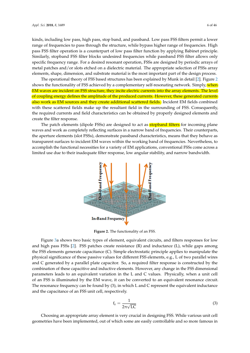
The operational theory of FSS based structures has been explained by Munk in detail [2]. Figure 2
shows the functionality of FSS achieved by a complementary self-resonating network. Simply, when
EM waves are incident on FSS structure, they incite electric currents into the array elements. The level
of coupling energy defines the amplitude of the produced currents. However, these generated currents
also work as EM sources and they create additional scattered fields. Incident EM fields combined
with these scattered fields make up the resultant field in the surrounding of FSS. Consequently,
the required currents and field characteristics can be obtained by properly designed elements and
create the filter response.
The patch elements (dipole FSSs) are designed to act as stopband filters for incoming plane
waves and work as completely reflecting surfaces in a narrow band of frequencies. Their counterparts,
the aperture elements (slot FSSs), demonstrate passband characteristics, means that they behave as
transparent surfaces to incident EM waves within the working band of frequencies. Nevertheless, to
accomplish the functional necessities for a variety of EM applications, conventional FSSs come across a
limited use due to their inadequate filter response, low angular stability, and narrow bandwidth.
Figure 2. The functionality of an FSS.
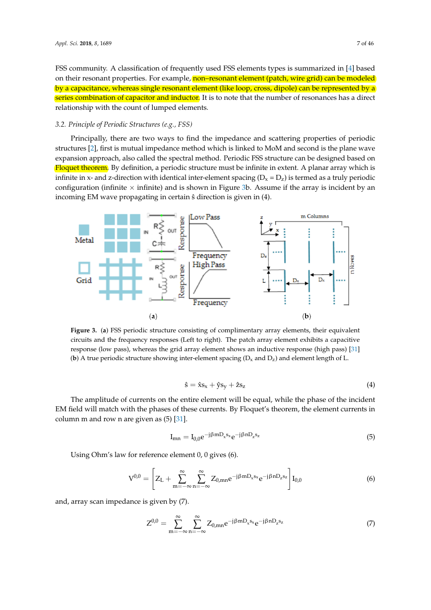
Figure 3a shows two basic types of element, equivalent circuits, and filters responses for low
and high pass FSSs [2]. FSS patches create resistance (R) and inductance (L), while gaps among
the FSS elements generate capacitance (C). Simple electrostatic principle applies to manipulate the
physical significance of these passive values for different FSS elements, e.g., L of two parallel wires
and C generated by a parallel plate capacitor. So, a required filter response is constructed by the
combination of these capacitive and inductive elements. However, any change in the FSS dimensional
parameters leads to an equivalent variation in the L and C values. Physically, when a unit cell
of an FSS is illuminated by the EM wave, it can be converted to an equivalent resonance circuit.
The resonance frequency can be found by (3), in which L and C represent the equivalent inductance
and the capacitance of an FSS unit cell, respectively.
fr =
√
1
2π
LC
(3)
Choosing an appropriate array element is very crucial in designing FSS. While various unit cell
geometries have been implemented, out of which some are easily controllable and so more famous in
�
Appl. Sci. 2018, 8, 1689
7 of 46
FSS community. A classification of frequently used FSS elements types is summarized in [4] based
on their resonant properties. For example, non–resonant element (patch, wire grid) can be modeled
by a capacitance, whereas single resonant element (like loop, cross, dipole) can be represented by a
series combination of capacitor and inductor. It is to note that the number of resonances has a direct
relationship with the count of lumped elements.
3.2. Principle of Periodic Structures (e.g., FSS)
Principally, there are two ways to find the impedance and scattering properties of periodic
structures [2], first is mutual impedance method which is linked to MoM and second is the plane wave
expansion approach, also called the spectral method. Periodic FSS structure can be designed based on
Floquet theorem. By definition, a periodic structure must be infinite in extent. A planar array which is
infinite in x- and z-direction with identical inter-element spacing (Dx = Dz) is termed as a truly periodic
configuration (infinite × infinite) and is shown in Figure 3b. Assume if the array is incident by an
incoming EM wave propagating in certain ˆs direction is given in (4).
Figure 3. (a) FSS periodic structure consisting of complimentary array elements, their equivalent
circuits and the frequency responses (Left to right). The patch array element exhibits a capacitive
response (low pass), whereas the grid array element shows an inductive response (high pass) [31]
(b) A true periodic structure showing inter-element spacing (Dx and Dz) and element length of L.
ˆs = ˆxsx + ˆysy + ˆzsz
(4)
The amplitude of currents on the entire element will be equal, while the phase of the incident
EM field will match with the phases of these currents. By Floquet’s theorem, the element currents in
column m and row n are given as (5) [31].
Imn = I0,0e−jβmDxsxe−jβnDzsz
Using Ohm’s law for reference element 0, 0 gives (6).
V0,0 =
ZL +
∞
∑
m=−∞
∞
∑
n=−∞
Z0,mne−jβmDxsxe−jβnDzsz
and, array scan impedance is given by (7).
Z0,0 =
∞
∑
m=−∞
∞
∑
n=−∞
Z0,mne−jβmDxsxe−jβnDzsz
I0,0
(5)
(6)
(7)
�
Appl. Sci. 2018, 8, 1689
8 of 46
3.3. History and Significant Advances of FSS in Recent Years
FSSs have extensively been explored over the past five decades [2,3] and the evolution process
extends from simple geometries to the complex designs. Strict requirements of performance
in advanced applications have stimulated considerable advancements in analytical techniques,
computational power management, and manufacturing technology. Huge potential for military
use has lead to intensive studies of such surfaces since mid-1960s. Although on record, the oldest
patent came in 1919 to the well-known Marconi and Franklin. The earlier FSSs research focused on
developing Cassegrain sub reflectors used in the parabolic antennas. During the Persian Gulf War,
the Lockheed F-117 Nighthawk was openly launched by US air force, which increased the significance
of stealth technology and FSSs. Although the adjustment of radar cross section is considered as the most
thrilling function of this technology, FSS are employed in many other useful applications. These include
dichroic sub-reflectors, radomes, RFIDs, lenses, and electromagnetic interference (EMI) protection.
Mode matching methods were initially applied in waveguide problems for the behavior analysis
of FSS, which gave rise to approach for equivalent circuit modeling [43]. This was partially based on the
transmission line theory. However, it had a limited analysis capability to model the FSS geometry. More
precise numerical techniques have been developed with the introduction of fast processing computers
e.g., MoM, FEM, FDTD, and IEM/BEM. Verification process has now replaced the bolometer used in
earlier experiments with modern Vector Network Analyzers with high capabilities of measurements
for amplitude and phase of the scattered EM fields. Fabrication ease and cost effectiveness are essential
factors that are investigated so far, since the precision in etching defines the performance of an FSS and
it is usually required to be achieved over vast areas of such surface.
Starting with a simple FSS or multiple cascaded FSS realizing a band-pass or band-stop
characteristic, the slot and patch elements are complementary and are linked by Babinet principle.
Generally, FSS applications presume those geometries which are periodic and represented by a unit
cell repeating itself indefinitely [2]. However, several practical applications of non-periodicity exist,
for example, in the use of curved surfaces, and infinite smooth surfaces, which may have randomness in
geometry and its constituent properties [43]. Moreover, the selection of direction-dependent screening
has been achieved by non-reciprocal FSS structures. Some initial uses of FSS lie in the design of radomes
and sub-reflectors for reflector antennas and still extensively studied. Capabilities of functioning at
lower frequencies and broader bandwidth have been facilitated by the lightweight, conductor-backed
thin radar absorbing FSSs.
Furthermore, since the “metamaterial” term was coined, there has been a stirring revitalization
of interest in metamaterial EM structures, especially metamaterial inspired FSSs are investigated
for compact filters, absorbers, and sensing applications. Recently, periodic structures having
three-dimensional (3D) elements is being used with great interest as they allow the electric currents
to flow with components at right angles to the surface and therefore, FSS geometries insensitive to
the incidence angles may be designed [43]. Complex FSS structures are manufactured with advanced
fabrication techniques by joining together consecutive layers of different shapes, such as tetrahedral
Calthrop, is fabricated with a printer employing the fabrication process of fuse-filament.
With the increase in satellite communication and pulse-powered devices, metallic FSSs have
been proved incapable to operate the power/heat produced by such systems efficiently. In such
applications, enhanced field, heat generated by Ohmic-losses, and dangerous emission of electrons,
are exceedingly frequent problems that result in the flashover and electric discharge. Quite recently,
a miniature element FSS has been encapsulated in a dielectric by means of a high break-down power
to minimize the amplitude of the electric field [48]. Peak power of about 25 kW could be handled with
this method. From the above illustration, it is evident that FSS is a massively growing area and needs
more state-of-the-art methodologies and innovative research to support foreseen novel applications
of FSSs.
�


 2023年江西萍乡中考道德与法治真题及答案.doc
 2012年重庆南川中考生物真题及答案.doc
 2013年江西师范大学地理学综合及文艺理论基础考研真题.doc
 2020年四川甘孜小升初语文真题及答案I卷.doc
 2020年注册岩土工程师专业基础考试真题及答案.doc
 2023-2024学年福建省厦门市九年级上学期数学月考试题及答案.doc
 2021-2022学年辽宁省沈阳市大东区九年级上学期语文期末试题及答案.doc
 2022-2023学年北京东城区初三第一学期物理期末试卷及答案.doc
 2018上半年江西教师资格初中地理学科知识与教学能力真题及答案.doc
 2012年河北国家公务员申论考试真题及答案-省级.doc
 2020-2021学年江苏省扬州市江都区邵樊片九年级上学期数学第一次质量检测试题及答案.doc
 2022下半年黑龙江教师资格证中学综合素质真题及答案.doc