3GPP TR 25.996 V11.0.0 (2012-09)
Technical Report
3rd Generation Partnership Project;
Technical Specification Group Radio Access Network;
Spatial channel model for
Multiple Input Multiple Output (MIMO) simulations
(Release 11)
The present document has been developed within the 3rd Generation Partnership Project (3GPP TM) and may be further elaborated for the purposes of 3GPP.
The present document has not been subject to any approval process by the 3GPP Organizational Partners and shall not be implemented.
This Specification is provided for future development work within 3GPP only. The Organizational Partners accept no liability for any use of this Specification.
Specifications and reports for implementation of the 3GPP TM system should be obtained via the 3GPP Organizational Partners' Publications Offices.
�
Release 11
2
3GPP TR 25.996 V11.0.0 (2012-09)
Keywords
UMTS, radio, antenna
3GPP
Postal address
3GPP support office address
650 Route des Lucioles - Sophia Antipolis
Valbonne - FRANCE
Tel.: +33 4 92 94 42 00 Fax: +33 4 93 65 47 16
Internet
http://www.3gpp.org
Copyright Notification
No part may be reproduced except as authorized by written permission.
The copyright and the foregoing restriction extend to reproduction in all media.
© 2012, 3GPP Organizational Partners (ARIB, ATIS, CCSA, ETSI, TTA, TTC).
All rights reserved.
UMTS™ is a Trade Mark of ETSI registered for the benefit of its members
3GPP™ is a Trade Mark of ETSI registered for the benefit of its Members and of the 3GPP Organizational Partners
LTE™ is a Trade Mark of ETSI currently being registered for the benefit of its Members and of the 3GPP Organizational Partners
GSM® and the GSM logo are registered and owned by t he GSM Association
3GPP
�
Release 11
3
3GPP TR 25.996 V11.0.0 (2012-09)
Contents
Foreword............................................................................................................................................................. 4
Scope ........................................................................................................................................................ 5
1
References ................................................................................................................................................ 5
2
3
Definitions, symbols and abbreviations ................................................................................................... 6
Definitions ......................................................................................................................................................... 6
3.1
Symbols ............................................................................................................................................................. 6
3.2
3.3
Abbreviations ..................................................................................................................................................... 6
Spatial channel model for calibration purposes ....................................................................................... 6
4
Purpose .............................................................................................................................................................. 6
4.1
4.2
Link level channel model parameter summary .................................................................................................. 7
4.3
Spatial parameters per path ................................................................................................................................ 8
4.4
BS and MS array topologies .............................................................................................................................. 8
Spatial parameters for the BS ............................................................................................................................ 8
4.5
4.5.1
BS antenna pattern ....................................................................................................................................... 8
4.5.2
Per-path BS angle spread (AS) ................................................................................................................... 10
4.5.3
Per-path BS angle of departure .................................................................................................................. 11
Per-path BS power azimuth spectrum ........................................................................................................ 11
4.5.4
Spatial parameters for the MS.......................................................................................................................... 11
4.6
4.6.1
MS antenna pattern .................................................................................................................................... 11
4.6.2
Per-path MS angle spread (AS) .................................................................................................................. 11
Per-path MS angle of arrival ...................................................................................................................... 11
4.6.3
Per-path MS power azimuth spectrum ....................................................................................................... 12
4.6.4
4.6.5
MS direction of travel ................................................................................................................................ 12
4.6.6
Per-path Doppler spectrum ......................................................................................................................... 13
4.7
Generation of channel model ........................................................................................................................... 13
Calibration and reference values ...................................................................................................................... 13
4.8
Spatial channel model for simulations ................................................................................................... 13
5
5.1
General definitions, parameters, and assumptions ........................................................................................... 14
Environments ................................................................................................................................................... 16
5.2
Generating user parameters.............................................................................................................................. 18
5.3
5.3.1
Generating user parameters for urban macrocell and suburban macrocell environments .......................... 18
5.3.2
Generating user parameters for urban microcell environments .................................................................. 20
5.4
Generating channel coefficients ....................................................................................................................... 22
Optional system simulation features ................................................................................................................ 23
5.5
5.5.1
Polarized arrays .......................................................................................................................................... 23
5.5.2
Far scatterer clusters ................................................................................................................................... 25
5.5.3
Line of sight ............................................................................................................................................... 26
5.5.4
Urban canyon ............................................................................................................................................. 27
Correlation between channel parameters ......................................................................................................... 28
5.6
5.7
Modeling intercell interference ........................................................................................................................ 29
5.8
System Level Calibration ................................................................................................................................. 30
Calculation of circular angle spread ................................................................................... 38
Annex A:
Change history ...................................................................................................................... 40
Annex B:
3GPP
�
Release 11
4
3GPP TR 25.996 V11.0.0 (2012-09)
Foreword
This Technical Report has been produced by the 3rd Generation Partnership Project (3GPP).
The contents of the present document are subject to(从属于) continuing work within the TSG(技术服务工作组)
and may change following formal TSG approval. Should the TSG modify the contents of the present document, it will
be re-released by the TSG with an identifying change of release date and an increase in version number as follows:
Version x.y.z
where:
x
the first digit:
1 presented to TSG for information;
2 presented to TSG for approval;
3 or greater indicates TSG approved document under change control.
y the second digit is incremented for all changes of substance, i.e. technical enhancements, corrections, updates,
etc.
z
the third digit is incremented when editorial only changes have been incorporated in the document.
3GPP
�
Release 11
5
3GPP TR 25.996 V11.0.0 (2012-09)
Scope(范围)
1
The present document details the output of the combined 3GPP-3GPP2 spatial channel model (SCM) ad-hoc(特别工
作组) group (AHG).
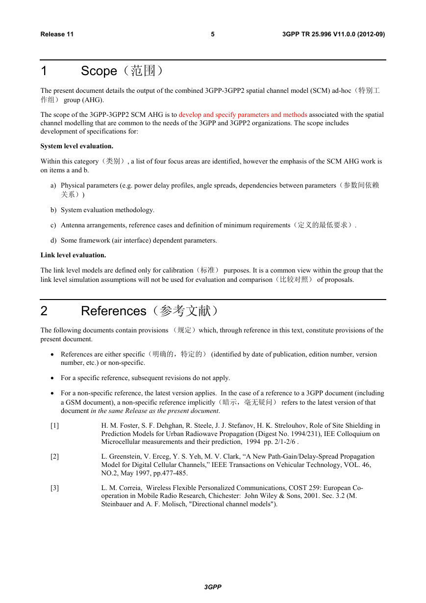
The scope of the 3GPP-3GPP2 SCM AHG is to develop and specify parameters and methods associated with the spatial
channel modelling that are common to the needs of the 3GPP and 3GPP2 organizations. The scope includes
development of specifications for:
System level evaluation.
Within this category(类别), a list of four focus areas are identified, however the emphasis of the SCM AHG work is
on items a and b.
a) Physical parameters (e.g. power delay profiles, angle spreads, dependencies between parameters(参数间依赖
关系))
b) System evaluation methodology.
c) Antenna arrangements, reference cases and definition of minimum requirements(定义的最低要求).
d) Some framework (air interface) dependent parameters.
Link level evaluation.
The link level models are defined only for calibration(标准) purposes. It is a common view within the group that the
link level simulation assumptions will not be used for evaluation and comparison(比较对照) of proposals.
References(参考文献)
2
The following documents contain provisions (规定)which, through reference in this text, constitute provisions of the
present document.
References are either specific(明确的,特定的) (identified by date of publication, edition number, version
number, etc.) or non-specific.
For a specific reference, subsequent revisions do not apply.
For a non-specific reference, the latest version applies. In the case of a reference to a 3GPP document (including
a GSM document), a non-specific reference implicitly(暗示,毫无疑问) refers to the latest version of that
document in the same Release as the present document.
[1]
[2]
[3]
H. M. Foster, S. F. Dehghan, R. Steele, J. J. Stefanov, H. K. Strelouhov, Role of Site Shielding in
Prediction Models for Urban Radiowave Propagation (Digest No. 1994/231), IEE Colloquium on
Microcellular measurements and their prediction, 1994 pp. 2/1-2/6 .
L. Greenstein, V. Erceg, Y. S. Yeh, M. V. Clark, “A New Path-Gain/Delay-Spread Propagation
Model for Digital Cellular Channels,” IEEE Transactions on Vehicular Technology, VOL. 46,
NO.2, May 1997, pp.477-485.
L. M. Correia, Wireless Flexible Personalized Communications, COST 259: European Co-
operation in Mobile Radio Research, Chichester: John Wiley & Sons, 2001. Sec. 3.2 (M.
Steinbauer and A. F. Molisch, "Directional channel models").
3GPP
�
Release 11
3
6
3GPP TR 25.996 V11.0.0 (2012-09)
Definitions, symbols(符号) and abbreviations(缩
写)
Definitions
3.1
For the purposes of the present document, the following terms and definitions apply.
Path: Ray
Path Component: Sub-ray
Symbols
3.2
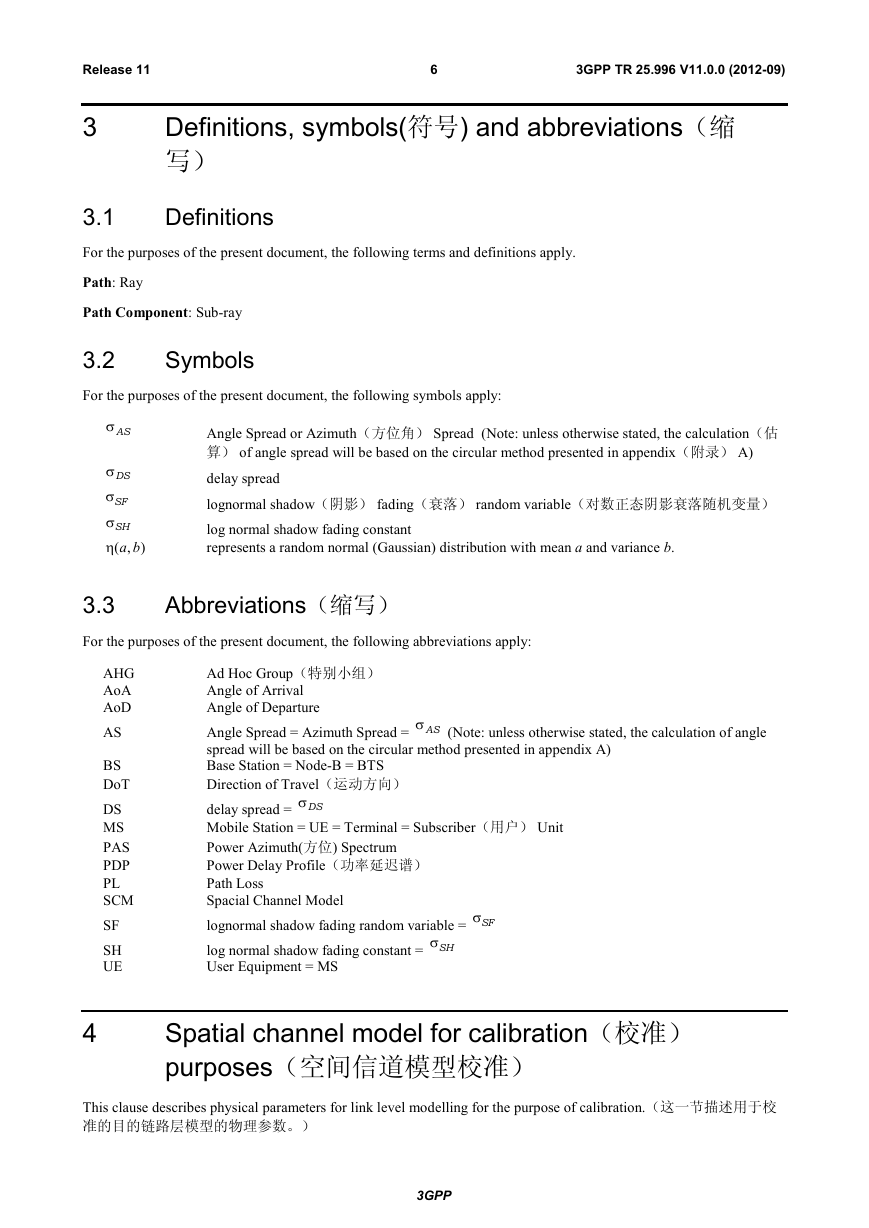
For the purposes of the present document, the following symbols apply:
AS
Angle Spread or Azimuth(方位角) Spread (Note: unless otherwise stated, the calculation(估
算) of angle spread will be based on the circular method presented in appendix(附录) A)
delay spread
lognormal shadow(阴影) fading(衰落) random variable(对数正态阴影衰落随机变量)
log normal shadow fading constant
represents a random normal (Gaussian) distribution with mean a and variance b.
DS
SF
SH
),( ba
3.3
For the purposes of the present document, the following abbreviations apply:
Abbreviations(缩写)
AHG
AoA
AoD
AS
BS
DoT
DS
MS
PAS
PDP
PL
SCM
SF
SH
UE
(Note: unless otherwise stated, the calculation of angle
Ad Hoc Group(特别小组)
Angle of Arrival
Angle of Departure
Angle Spread = Azimuth Spread = AS
spread will be based on the circular method presented in appendix A)
Base Station = Node-B = BTS
Direction of Travel(运动方向)
delay spread = DS
Mobile Station = UE = Terminal = Subscriber(用户) Unit
Power Azimuth(方位) Spectrum
Power Delay Profile(功率延迟谱)
Path Loss
Spacial Channel Model
lognormal shadow fading random variable = SF
log normal shadow fading constant = SH
User Equipment = MS
4
Spatial channel model for calibration(校准)
purposes(空间信道模型校准)
This clause describes physical parameters for link level modelling for the purpose of calibration.(这一节描述用于校
准的目的链路层模型的物理参数。)
3GPP
�
Release 11
7
3GPP TR 25.996 V11.0.0 (2012-09)
Purpose
4.1
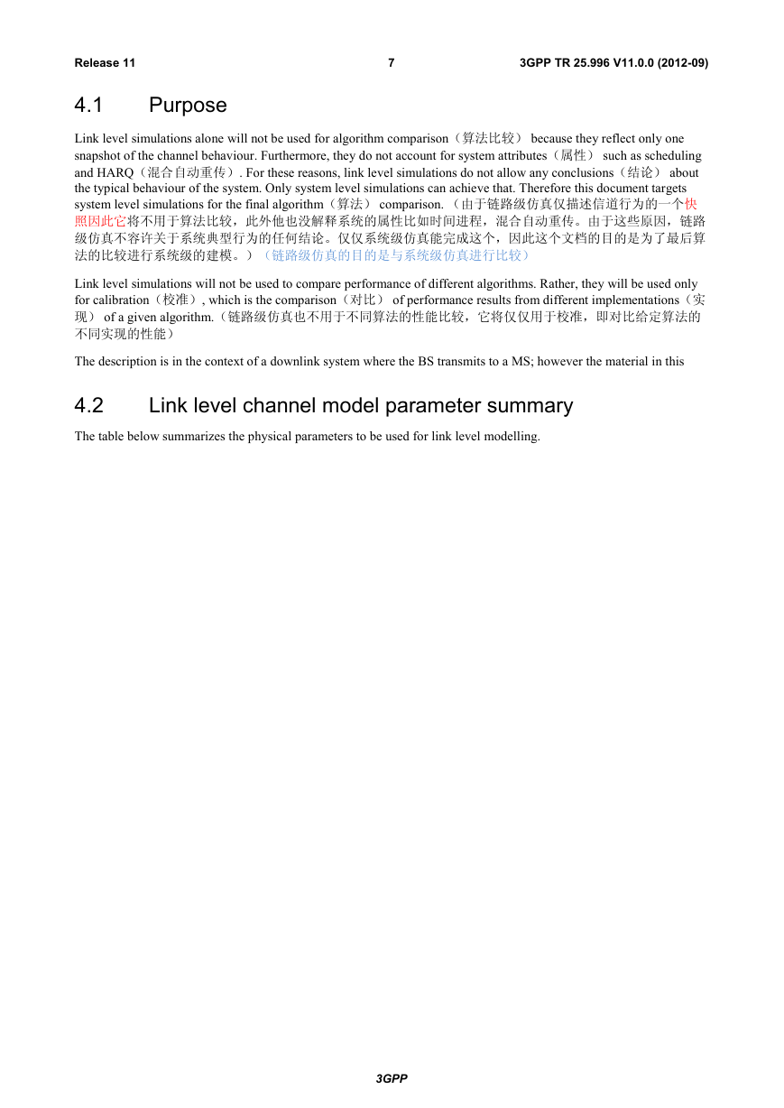
Link level simulations alone will not be used for algorithm comparison(算法比较) because they reflect only one
snapshot of the channel behaviour. Furthermore, they do not account for system attributes(属性) such as scheduling
and HARQ(混合自动重传). For these reasons, link level simulations do not allow any conclusions(结论) about
the typical behaviour of the system. Only system level simulations can achieve that. Therefore this document targets
system level simulations for the final algorithm(算法) comparison. (由于链路级仿真仅描述信道行为的一个快
照因此它将不用于算法比较,此外他也没解释系统的属性比如时间进程,混合自动重传。由于这些原因,链路
级仿真不容许关于系统典型行为的任何结论。仅仅系统级仿真能完成这个,因此这个文档的目的是为了最后算
法的比较进行系统级的建模。)(链路级仿真的目的是与系统级仿真进行比较)
Link level simulations will not be used to compare performance of different algorithms. Rather, they will be used only
for calibration(校准), which is the comparison(对比) of performance results from different implementations(实
现) of a given algorithm.(链路级仿真也不用于不同算法的性能比较,它将仅仅用于校准,即对比给定算法的
不同实现的性能)
The description is in the context of a downlink system where the BS transmits to a MS; however the material in this
Link level channel model parameter summary
4.2
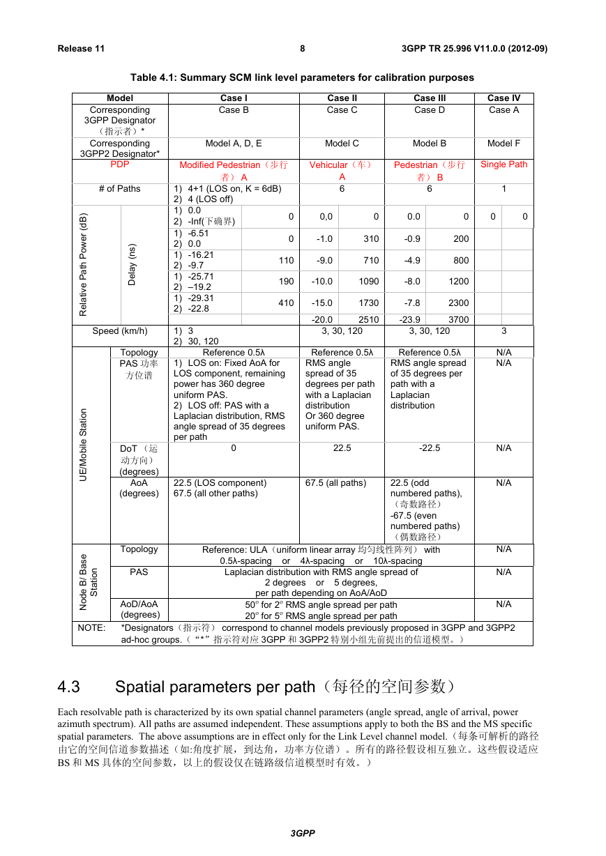
The table below summarizes the physical parameters to be used for link level modelling.
3GPP
�
Release 11
8
3GPP TR 25.996 V11.0.0 (2012-09)
Table 4.1: Summary SCM link level parameters for calibration purposes
Case I
Case B
Case II
Case C
Case III
Case D
Case IV
Case A
Model A, D, E
Model C
Model B
Model F
Vehicular(车)
A
6
Pedestrian(步行
者) B
6
Single Path
1
0
0
0
Modified Pedestrian(步行
者) A
0
0
110
190
410
1) 4+1 (LOS on, K = 6dB)
2) 4 (LOS off)
1) 0.0
2) -Inf(下确界)
1) -6.51
2) 0.0
1) -16.21
2) -9.7
1) -25.71
2) –19.2
1) -29.31
2) -22.8
1) 3
2) 30, 120
Reference 0.5λ
1) LOS on: Fixed AoA for
LOS component, remaining
power has 360 degree
uniform PAS.
2) LOS off: PAS with a
Laplacian distribution, RMS
angle spread of 35 degrees
per path
0
0,0
-1.0
-9.0
0
310
710
0.0
-0.9
-4.9
200
800
-10.0
1090
-8.0
1200
-15.0
-20.0
1730
2510
3, 30, 120
-7.8
-23.9
2300
3700
3, 30, 120
Reference 0.5λ
RMS angle
spread of 35
degrees per path
with a Laplacian
distribution
Or 360 degree
uniform PAS.
Reference 0.5λ
RMS angle spread
of 35 degrees per
path with a
Laplacian
distribution
22.5
-22.5
3
N/A
N/A
N/A
N/A
N/A
N/A
Model
Corresponding
3GPP Designator
(指示者)*
Corresponding
3GPP2 Designator*
PDP
# of Paths
)
s
n
(
y
a
e
D
l
Speed (km/h)
Topology
PAS 功率
方位谱
)
B
d
(
r
e
w
o
P
h
t
a
P
e
v
i
t
l
a
e
R
n
o
i
t
DoT (运
动方向)
(degrees)
AoA
(degrees)
Topology
PAS
t
a
S
e
l
i
b
o
M
E
U
/
e
s
a
B
/
B
e
d
o
N
n
o
i
t
t
a
S
NOTE:
22.5 (LOS component)
67.5 (all other paths)
67.5 (all paths)
22.5 (odd
numbered paths),
(奇数路径)
-67.5 (even
numbered paths)
(偶数路径)
Reference: ULA(uniform linear array 均匀线性阵列) with
0.5λ-spacing or 4λ-spacing or 10λ-spacing
Laplacian distribution with RMS angle spread of
2 degrees or 5 degrees,
per path depending on AoA/AoD
AoD/AoA
(degrees)
*Designators(指示符) correspond to channel models previously proposed in 3GPP and 3GPP2
ad-hoc groups.(“*”指示符对应 3GPP 和 3GPP2 特别小组先前提出的信道模型。)
50 for 2 RMS angle spread per path
20 for 5 RMS angle spread per path
N/A
Spatial parameters per path(每径的空间参数)
4.3
Each resolvable path is characterized by its own spatial channel parameters (angle spread, angle of arrival, power
azimuth spectrum). All paths are assumed independent. These assumptions apply to both the BS and the MS specific
spatial parameters. The above assumptions are in effect only for the Link Level channel model.(每条可解析的路径
由它的空间信道参数描述(如:角度扩展,到达角,功率方位谱)。所有的路径假设相互独立。这些假设适应
BS 和 MS 具体的空间参数,以上的假设仅在链路级信道模型时有效。)
3GPP
�


 2023年江西萍乡中考道德与法治真题及答案.doc
 2012年重庆南川中考生物真题及答案.doc
 2013年江西师范大学地理学综合及文艺理论基础考研真题.doc
 2020年四川甘孜小升初语文真题及答案I卷.doc
 2020年注册岩土工程师专业基础考试真题及答案.doc
 2023-2024学年福建省厦门市九年级上学期数学月考试题及答案.doc
 2021-2022学年辽宁省沈阳市大东区九年级上学期语文期末试题及答案.doc
 2022-2023学年北京东城区初三第一学期物理期末试卷及答案.doc
 2018上半年江西教师资格初中地理学科知识与教学能力真题及答案.doc
 2012年河北国家公务员申论考试真题及答案-省级.doc
 2020-2021学年江苏省扬州市江都区邵樊片九年级上学期数学第一次质量检测试题及答案.doc
 2022下半年黑龙江教师资格证中学综合素质真题及答案.doc