Meridian Innovation MI48xx
Thermal Image Processor
Data sheet
Revision 3.1.3 – June 2022
Firmware compatibility: 3.3.1 or higher
�
MI48xx Data Sheet
Contents
1.
DESCRIPTION ...................................................................................................................................... 4
2.
ORDER INFORMATION ..................................................................................................................... 5
3.
PINOUT INFORMATION .................................................................................................................... 5
3.1.
Pin Configuration – MI48Ax, SPI/I2C Interface ................................................................................................... 5
3.2.
Pin Configuration – MI48BX, USB Interface ....................................................................................................... 6
3.3.
Pin Description .................................................................................................................................................. 7
3.4.
Special Pin Handling .......................................................................................................................................... 9
4.
FUNCTIONAL DESCRIPTION ........................................................................................................ 10
4.1. Architectural Overview .................................................................................................................................... 10
SenXor Bus Interface ....................................................................................................................................... 10
I2C Bus Interface .............................................................................................................................................. 10
SPI Interface .................................................................................................................................................... 10
USB Interface .................................................................................................................................................. 11
Data Frame Buffers and Thermal Image Processing ....................................................................................... 11
4.1.1.
4.1.2.
4.1.3.
4.1.4.
4.1.5.
4.2. MI48xx Register Map ....................................................................................................................................... 11
4.3. Detailed Register Description ........................................................................................................................... 12
4.4.
SenXor Bus Interface ........................................................................................................................................ 18
4.5.
I2C Bus Interface (MI48Ax) ............................................................................................................................... 18
I2C Slave Address ............................................................................................................................................. 19
4.5.1.
I2C Command .................................................................................................................................................. 19
4.5.2.
4.5.3. Write Command .............................................................................................................................................. 19
4.5.4.
Read Command ............................................................................................................................................... 19
4.6.
SPI Interface (MI48Ax) ..................................................................................................................................... 20
SPI Interface Operation ................................................................................................................................... 20
Thermal Data Frame Format ........................................................................................................................... 21
Thermal Data Frame Header Details ............................................................................................................... 21
Temperature Data ........................................................................................................................................... 22
4.6.1.
4.6.2.
4.6.3.
4.6.4.
4.7.
Thermal Data Acquisition ................................................................................................................................. 22
4.8.
Thermal Data Readout ..................................................................................................................................... 22
General Considerations................................................................................................................................... 22
Low Power Considerations ............................................................................................................................. 23
4.8.1.
4.8.2.
4.9.
Low-level Thermal Data Processing .................................................................................................................. 23
Per Pixel Calibration ........................................................................................................................................ 23
Bad Pixel Correction ........................................................................................................................................ 23
4.9.1.
4.9.2.
Version 3.1.3, June 2022
CONFIDENTIAL: UNDER NDA
2
�
MI48xx Data Sheet
4.9.3.
4.9.4.
Camera Module Output to Temperature Conversion..................................................................................... 24
Data Filtering ................................................................................................................................................... 24
4.10.
Accessing User Flash ..................................................................................................................................... 25
5.
ELECTRICAL AND THERMAL CHARACTERISTICS ................................................................. 26
5.1. Absolute Maximum Rating ............................................................................................................................... 26
5.2. Nominal Operating Conditions ......................................................................................................................... 27
6.
DYNAMIC TIMING CHARACTERISTICS ..................................................................................... 27
6.1. MI48xx Clock .................................................................................................................................................... 27
6.2. MI48xx Reset ................................................................................................................................................... 27
Normal power up ............................................................................................................................................ 28
First time power-up ........................................................................................................................................ 28
6.2.1.
6.2.2.
6.3.
I2C Characteristics............................................................................................................................................. 28
6.4.
SPI Interface ..................................................................................................................................................... 29
7.
PACKAGE INFORMATION ............................................................................................................. 30
8.
REFERENCE DESIGN ....................................................................................................................... 31
8.1. MI48Ax – SPI/I2C Interface to Host .................................................................................................................. 31
Reference Circuit............................................................................................................................................. 31
Bill of Materials ............................................................................................................................................... 32
8.1.1.
8.1.2.
8.2. MI48Bx – USB Interface to Host ....................................................................................................................... 33
Reference Circuit............................................................................................................................................. 33
8.2.1.
9.
PCB DESIGN CONSIDERATIONS .................................................................................................. 33
10. REVISION HISTORY......................................................................................................................... 34
11. LEGAL INFORMATION .................................................................................................................... 36
12. CONTACTS INFORMATION ........................................................................................................... 36
13. APPENDIX I ........................................................................................................................................ 37
Version 3.1.3, June 2022
CONFIDENTIAL: UNDER NDA
3
�
MI48xx Data Sheet
1.
DESCRIPTION
Meridian Innovation’s MI48XX is a specialised integrated circuit (IC) that is a companion to
the MI08XX camera module featuring SenXorTM long-wave infrared (LWIR) imaging sensor.
The MI48XX handles the low-level control signalling necessary to capture raw sensor data
from the thermal imaging array. It also provides standard interfaces for communication
with a host controller.
The MI48XX is currently available in two different versions, each version supporting a
different interface to the host system. The MI48Ax has Inter-Integrated Circuit (I2C) bus –
for conveying commands to the MI48Ax and obtaining status from it, and serial peripheral
interface (SPI) – for readout of thermal data. The MI48Bx has a USB interface for
communicating both control/status and thermal data. The communication protocol that
must be used by the host application layer to exchange command-acknowledge type of
messages is specified elsewhere.
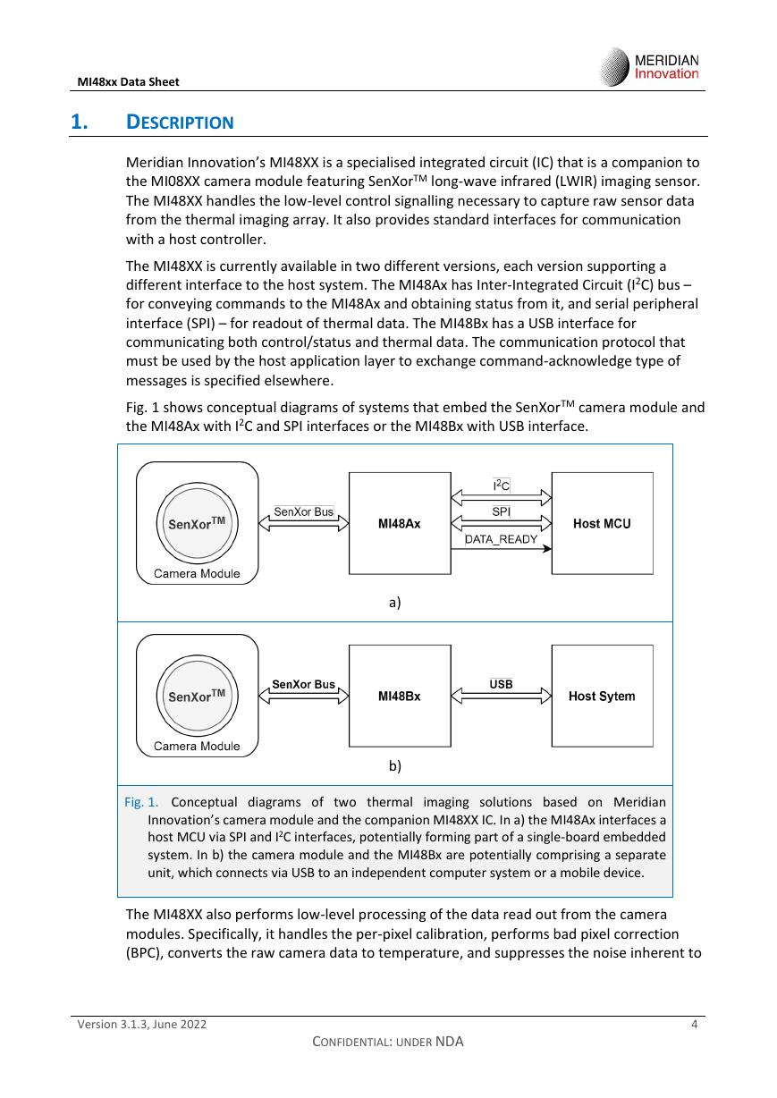
Fig. 1 shows conceptual diagrams of systems that embed the SenXorTM camera module and
the MI48Ax with I2C and SPI interfaces or the MI48Bx with USB interface.
a)
b)
Fig. 1. Conceptual diagrams of two thermal
imaging solutions based on Meridian
Innovation’s camera module and the companion MI48XX IC. In a) the MI48Ax interfaces a
host MCU via SPI and I2C interfaces, potentially forming part of a single-board embedded
system. In b) the camera module and the MI48Bx are potentially comprising a separate
unit, which connects via USB to an independent computer system or a mobile device.
The MI48XX also performs low-level processing of the data read out from the camera
modules. Specifically, it handles the per-pixel calibration, performs bad pixel correction
(BPC), converts the raw camera data to temperature, and suppresses the noise inherent to
Version 3.1.3, June 2022
CONFIDENTIAL: UNDER NDA
4
�
MI48xx Data Sheet
the signals coming from the pixels. In this way it greatly facilitates the development of
applications embedding the SenXorTM thermal imaging sensor.
The MI48XX is housed in a 5 mm by 5 mm, 32-pin leadless package featuring an exposed
bottom thermal pad – quad flat no-lead QFN33.
2. ORDER INFORMATION
Table 1.
ORDERING INFORMATION
Product Code
Package
MI48A3
MI48B3
QFN33 (plastic, quad-flat, no-leads,
thermal ground pad at the bottom)
QFN33 (plastic, quad-flat, no-leads,
thermal ground pad at the bottom)
Firmware
Version
3.3.1 or
higher
3.3.1 or
higher
Interface Min.
Quantity
SPI/I2C
100
USB
100
3.
PINOUT INFORMATION
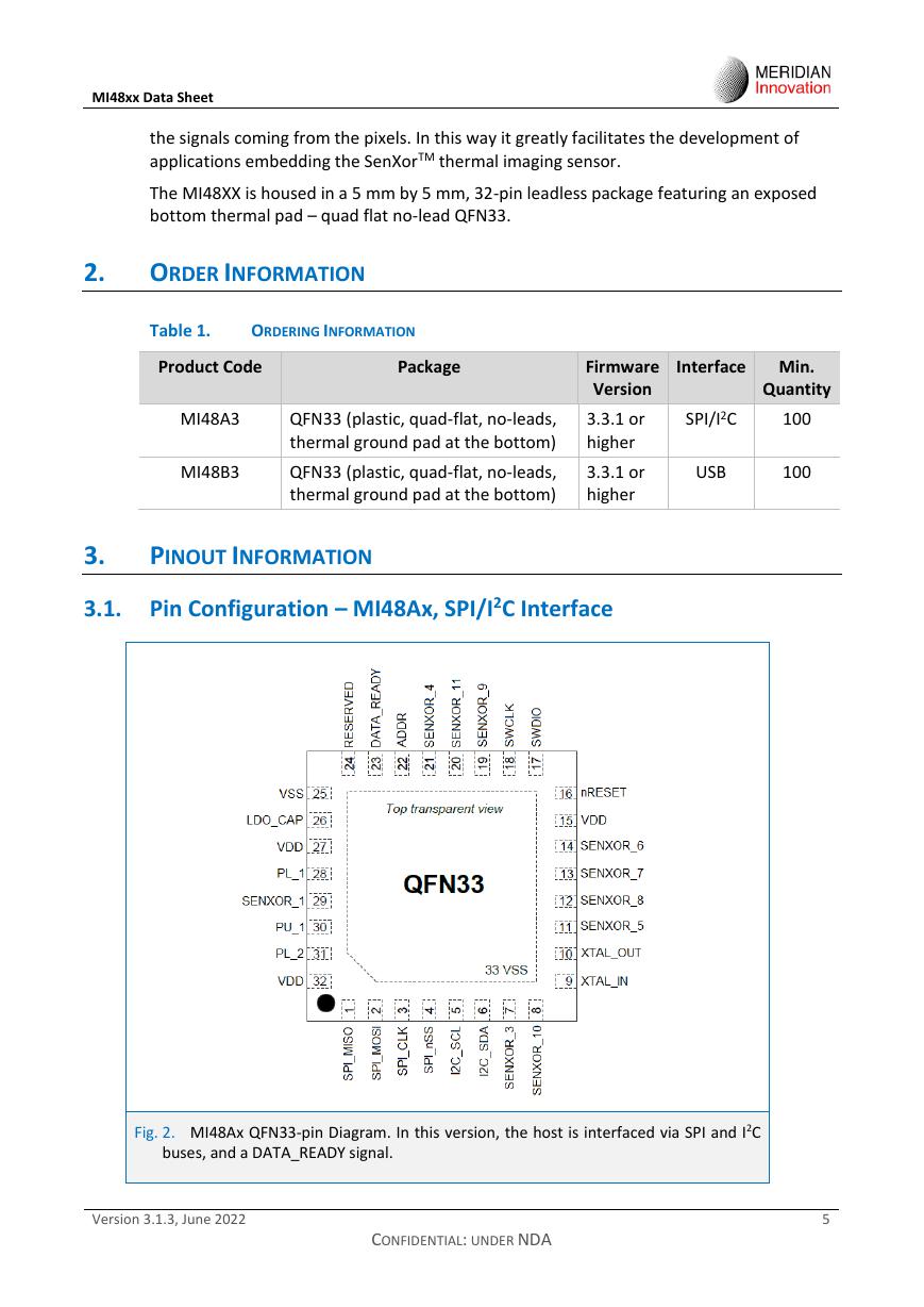
3.1. Pin Configuration – MI48Ax, SPI/I2C Interface
Fig. 2. MI48Ax QFN33-pin Diagram. In this version, the host is interfaced via SPI and I2C
buses, and a DATA_READY signal.
Version 3.1.3, June 2022
CONFIDENTIAL: UNDER NDA
5
�
MI48xx Data Sheet
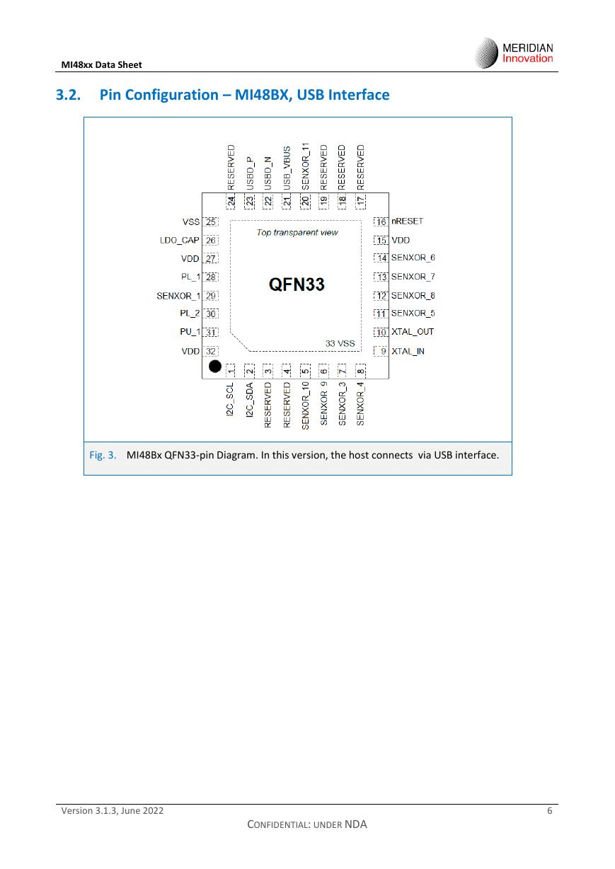
3.2. Pin Configuration – MI48BX, USB Interface
Fig. 3. MI48Bx QFN33-pin Diagram. In this version, the host connects via USB interface.
Version 3.1.3, June 2022
CONFIDENTIAL: UNDER NDA
6
�
MI48xx Data Sheet
3.3. Pin Description
Table 2.
PIN DESCRIPTION OF MI48AX 1)
PIN
NO.
1
2
3
4
5
6
7
8
9
10
11
12
13
14
15
16
17
18
19
20
21
22
23
24
25
26
27
28
29
30
31
32
PU_1
PL_2
VDD
33
VSS
PIN NAME
TYPE
DESCRIPTION
SPI_MISO
SPI_MOSI
SPI_CLK
SPI_nSS
I2C_SCL
I2C_SDA
SENXOR_3
SENXOR_10
XTAL_IN
XTAL_OUT
SENXOR_5
SENXOR_8
SENXOR_7
SENXOR_6
VDD
nRESET
SWDIO
SWCLK
SENXOR_9
SENXOR_11
SENXOR_4
ADDR
DATA_READY
RESERVED
VSS
LDO_CAP
VDD
PL_1
O
Master Input Slave Output of the SPI bus.
I
I
I
I
I/O
I/O
I/O
I
O
I/O
I/O
I/O
I/O
P
I
-
-
I/O
I/O
I/O
I
O
-
P
P
P
I
Master Output Slave Input of the SPI bus.
Serial Clock of the SPI bus.
Slave Select of the SPI bus.
Clock line of the I2C bus.
Data line of the I2C bus.
SenXor Bus. Connect directly to camera module pin: SENXOR_3.
SenXor Bus. Connect directly to camera module pin: SENXOR_10.
External 12MHz crystal input. Connect through a 18pF capacitor to ground.
External 12MHz crystal output. Connect through a 18pF capacitor to ground.
SenXor Bus. Connect directly to camera module pin: SENXOR_5.
SenXor Bus. Connect directly to camera module pin: SENXOR_8.
SenXor Bus. Connect directly to camera module pin: SENXOR_7.
SenXor Bus. Connect directly to camera module pin: SENXOR_6.
Power supply. Nominal 3.3 V.
Active low hardware reset.
Serial Wire Debug DATA.
Serial Wire Debug CLOCK.
SenXor Bus. Connect directly to camera module pin: SENXOR_9.
SenXor Bus. Connect directly to camera module pin: SENXOR_11.
SenXor Bus. Connect directly to camera module pin: SENXOR_4.
I2C chip select address.
Active high output.
Reserved pin. Do not connect.
Ground.
Internal LDO output pin. Connect through a 2.2uF capacitor to ground.
Power supply. Nominal 3.3V.
Pull low. Connected to ground via 10 kΩ resistor.
SENXOR_1
I/0
SenXor Bus. Connect directly to camera module pin: SENXOR_1.
I
I
P
P
Pull up. Connect to VDD via 10 kΩ resistor.
Pull low. Connected to ground via 10 kΩ resistor.
Power supply.
Thermal pad. Connect to ground.
1) The term ‘camera module’ in Table 2 and Table 3 refers to the MI08XXX camera module.
Version 3.1.3, June 2022
CONFIDENTIAL: UNDER NDA
7
�
MI48xx Data Sheet
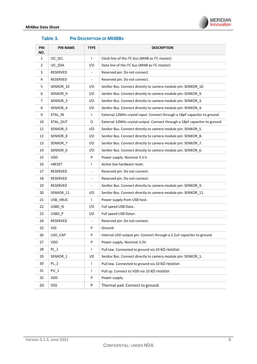
Table 3.
PIN DESCRIPTION OF MI48BX
PIN NAME
TYPE
DESCRIPTION
I2C_SCL
I2C_SDA
RESERVED
RESERVED
I
Clock line of the I2C bus (MI48 as I2C master)
I/O
Data line of the I2C bus (MI48 as I2C master)
-
-
Reserved pin. Do not connect.
Reserved pin. Do not connect.
SENXOR_10
I/O
SenXor Bus. Connect directly to camera module pin: SENXOR_10.
SENXOR_9
SENXOR_3
SENXOR_4
XTAL_IN
XTAL_OUT
SENXOR_5
SENXOR_8
SENXOR_7
SENXOR_6
VDD
nRESET
RESERVED
RESERVED
RESERVED
SENXOR_11
USB_VBUS
USBD_N
USBD_P
RESERVED
VSS
LDO_CAP
VDD
PL_1
I/O
I/O
I/O
I
O
I/O
I/O
I/O
I/O
P
I
-
-
-
SenXor Bus. Connect directly to camera module pin: SENXOR_9.
SenXor Bus. Connect directly to camera module pin: SENXOR_3.
SenXor Bus. Connect directly to camera module pin: SENXOR_4.
External 12MHz crystal input. Connect through a 18pF capacitor to ground.
External 12MHz crystal output. Connect through a 18pF capacitor to ground.
SenXor Bus. Connect directly to camera module pin: SENXOR_5.
SenXor Bus. Connect directly to camera module pin: SENXOR_8.
SenXor Bus. Connect directly to camera module pin: SENXOR_7.
SenXor Bus. Connect directly to camera module pin: SENXOR_6.
Power supply. Nominal 3.3 V.
Active low hardware reset.
Reserved pin. Do not connect.
Reserved pin. Do not connect.
SenXor Bus. Connect directly to camera module pin: SENXOR_9.
I/O
SenXor Bus. Connect directly to camera module pin: SENXOR_11.
I
Power supply from USB host.
I/O
I/O
Full speed USB Data-.
Full speed USB Data+.
-
P
P
P
I
Reserved pin. Do not connect.
Ground.
Internal LDO output pin. Connect through a 2.2uF capacitor to ground.
Power supply. Nominal 3.3V.
Pull low. Connected to ground via 10 kΩ resistor.
SENXOR_1
I/0
SenXor Bus. Connect directly to camera module pin: SENXOR_1.
I
I
P
P
Pull low. Connected to ground via 10 kΩ resistor.
Pull up. Connect to VDD via 10 kΩ resistor.
Power supply.
Thermal pad. Connect to ground.
PIN
NO.
1
2
3
4
5
6
7
8
9
10
11
12
13
14
15
16
17
18
19
20
21
22
23
24
25
26
27
28
29
30
31
32
PL_2
PU_1
VDD
33
VSS
Version 3.1.3, June 2022
8
CONFIDENTIAL: UNDER NDA
�



 V2版本原理图(Capacitive-Fingerprint-Reader-Schematic_V2).pdf
 摄像头工作原理.doc
 VL53L0X简要说明(En.FLVL53L00216).pdf
 原理图(DVK720-Schematic).pdf
 原理图(Pico-Clock-Green-Schdoc).pdf
 原理图(RS485-CAN-HAT-B-schematic).pdf
 File:SIM7500_SIM7600_SIM7800 Series_SSL_Application Note_V2.00.pdf
 ADS1263(Ads1262).pdf
 原理图(Open429Z-D-Schematic).pdf
 用户手册(Capacitive_Fingerprint_Reader_User_Manual_CN).pdf
 CY7C68013A(英文版)(CY7C68013A).pdf
 TechnicalReference_Dem.pdf