IT8951E
IT8951TE
IT8951VG
IT8951E-64
IT8951VG-64
EPD Timing Controller
Preliminary Specification V0.2.4.3
(For D Version)
ITE TECH. INC.
This specification is subject to Change without notice. It is provided “AS IS” and for reference only. For
purchasing information, please contact the nearest ITE TECH sales representatives.
Please note that the IT8951 V0.2.4.3 is applicable to the D version.
CONFIDENTIAL�
CONFIDENTIAL�
Copyright 2017 ITE Tech. Inc.
This is a Preliminary document release. All specifications are subject to change without notice.
The material contained in this document supersedes all previous material issued for the products herein
referenced. Please contact ITE Tech. Inc. for the latest document(s).
All sales are subject to ITE’s Standard Terms and Conditions, a copy of which is included in the back of this
document.
ITE, IT8951 is a trademark of ITE Tech. Inc.
All other trademarks are claimed by their respective owners.
All specifications are subject to change without notice.
Additional copies of this manual or other ITE literature may be obtained from:
If you have any marketing or sales questions, please contact:
P.Y. Chang, at ITE Taiwan:
E-mail: p.y.chang@ite.com.tw, Tel: 886-2-29126889 X6052, Fax: 886-2-29102551
You may also find the local sales representative nearest you on the ITE web site.
To find out more about ITE, visit our World Wide Web at:
http://www.ite.com.tw
Or e-mail itesupport@ite.com.tw for more product information/services
ITE Tech. Inc.
Marketing Department
7F, No.233-1, Baociao Rd., Sindian City,
Taipei County 23145, Taiwan, ROC
Tel:
Fax:
886-2-29126889
886-2-2910-2551, 886-2-2910-2552
CONFIDENTIAL�
CONFIDENTIAL�
Revision History
The contents below indicate the change between this version and the previous version only. The revision history
shown in the previous version will not remain in the following table.
Revision History
Section
-
Revision
Part IT8951VG in VFBGA 128 added
eMMC support added
Tables below in Pin Description section modified
Pin Description of Supplies Signals
Difference between IT8951E/IT8951TE/
IT8951E-64/IT8951VG/IT8951VG-64
Page No.
-
www.ite.com.tw
A
IT8951 V0.2.4.3
CONFIDENTIAL�
CONFIDENTIAL�
Contents
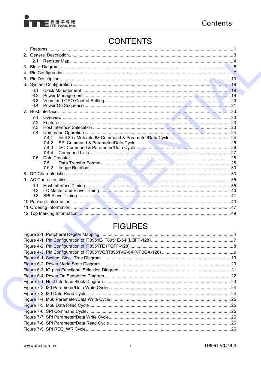
CONTENTS
1. Features ......................................................................................................................................................... 1
2. General Description........................................................................................................................................ 3
2.1 Register Map ....................................................................................................................................... 4
3. Block Diagram ................................................................................................................................................ 5
4. Pin Configuration ............................................................................................................................................ 7
5. Pin Description ............................................................................................................................................. 13
6. System Configuration ................................................................................................................................... 19
6.1 Clock Management ........................................................................................................................... 19
6.2 Power Management .......................................................................................................................... 19
6.3 Vcom and GPO Control Setting ........................................................................................................ 20
6.4 Power On Sequence ......................................................................................................................... 21
7. Host Interface ............................................................................................................................................... 23
7.1 Overview ............................................................................................................................................ 23
7.2 Features ............................................................................................................................................ 23
7.3 Host Interface Selecetion .................................................................................................................. 23
7.4 Command Operation ......................................................................................................................... 24
7.4.1
Intel 80 / Motorola 68 Command & Parameter/Data Cycle .................................................. 24
7.4.2 SPI Command & Parameter/Data Cycle .............................................................................. 25
7.4.3
I2C Command & Parameter/Data Cycle ............................................................................... 26
7.4.4 Command Lists ..................................................................................................................... 27
7.5 Data Transfer ..................................................................................................................................... 28
7.5.1 Data Transfer Format ........................................................................................................... 28
7.5.2
Image Rotation ..................................................................................................................... 30
8. DC Characteristics ....................................................................................................................................... 33
9. AC Characteristics ........................................................................................................................................ 35
9.1 Host Interface Timing ........................................................................................................................ 35
I2C Master and Slave Timing ............................................................................................................. 40
9.2
9.3 SPI Slave Timing ............................................................................................................................... 41
10. Package Information .................................................................................................................................... 43
11. Ordering Information .................................................................................................................................... 47
12. Top Marking Information .............................................................................................................................. 49
FIGURES
Figure 2-1. Peripheral Regiter Mapping .............................................................................................................. 4
Figure 4-1. Pin Configuration of IT8951E/IT8951E-64 (LQFP-128) .................................................................... 7
Figure 4-2. Pin Configuration of IT8951TE (TQFP-128) ..................................................................................... 8
Figure 4-3. Pin Configuration of IT8951VG/IT8951VG-64 (VFBGA-128) ........................................................... 9
Figure 6-1. System Clock Tree Diagram ........................................................................................................... 19
Figure 6-2. Power Mode State Diagram ............................................................................................................ 20
Figure 6-3. IO-pins Functional Selection Diagram ............................................................................................ 21
Figure 6-4. Power On Sequence Diagram ........................................................................................................ 22
Figure 7-1. Host Interface Block Diagram ......................................................................................................... 23
Figure 7-2. I80 Parameter/Data Write Cycle ..................................................................................................... 24
Figure 7-3. I80 Data Read Cycle ....................................................................................................................... 24
Figure 7-4. M68 Parameter/Data Write Cycle ................................................................................................... 25
Figure 7-5. M68 Data Read Cycle ..................................................................................................................... 25
Figure 7-6. SPI Command Cycle ....................................................................................................................... 25
Figure 7-7. SPI Parameter/Data Write Cycle..................................................................................................... 26
Figure 7-8. SPI Parameter/Data Read Cycle .................................................................................................... 26
Figure 7-9. SPI REG_WR Cycle ........................................................................................................................ 26
www.ite.com.tw
i
IT8951 V0.2.4.3
CONFIDENTIAL�
IT8951 (For D Version)
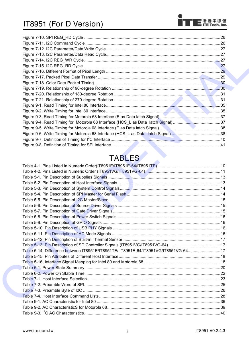
Figure 7-10. SPI REG_RD Cycle ...................................................................................................................... 26
Figure 7-11. I2C Command Cycle ..................................................................................................................... 26
Figure 7-12. I2C Parameter/Data Write Cycle ................................................................................................... 27
Figure 7-13. I2C Parameter/Data Read Cycle................................................................................................... 27
Figure 7-14. I2C REG_WR Cycle ...................................................................................................................... 27
Figure 7-15. I2C REG_RD Cycle ....................................................................................................................... 27
Figure 7-16. Different Format of Pixel Length ................................................................................................... 29
Figure 7-17. Packed Pixel Data Transfer .......................................................................................................... 29
Figure 7-18. Color Data Packet Timing ............................................................................................................. 30
Figure 7-19. Relationship of 90-degree Rotation .............................................................................................. 30
Figure 7-20. Relationship of 180-degree Rotation ............................................................................................ 31
Figure 7-21. Relationship of 270-degree Rotation ............................................................................................ 31
Figure 9-1. Read Timing for Intel 80 Interface ................................................................................................... 35
Figure 9-2. Write Timing for Intel 80 Interface ................................................................................................... 35
Figure 9-3. Read Timing for Motorola 68 Interface (E as Data latch Signal) .................................................... 37
Figure 9-4. Read Timing for Motorola 68 Interface (HCS_L as Data latch Signal) ......................................... 37
Figure 9-5. Write Timing for Motorola 68 Interface (E as Data latch Signal) ..................................................... 38
Figure 9-6. Write Timing for Motorola 68 Interface (HCS_L as Data latch Signal) .......................................... 38
Figure 9-7. Definition of Timing for I2C Interface ............................................................................................... 40
Figure 9-8. Definition of Timing for SPI Interface .............................................................................................. 41
TABLES
Table 4-1. Pins Listed in Numeric Order(IT8951E/IT8951E-64/IT8951TE) ...................................................... 10
Table 4-2. Pins Listed in Numeric Order (IT8951VG/IT8951VG-64) ................................................................. 11
Table 5-1. Pin Description of Supplies Signals ................................................................................................. 13
Table 5-2. Pin Description of Host Interface Signals ......................................................................................... 13
Table 5-3. Pin Description of System Control Signals ....................................................................................... 14
Table 5-4. Pin Description of SPI Master for Serial Flash ................................................................................. 14
Table 5-5. Pin Description of I2C Master/Slave ................................................................................................ 15
Table 5-6. Pin Description of Source Driver Signals ......................................................................................... 15
Table 5-7. Pin Description of Gate Driver Signals ............................................................................................. 15
Table 5-8. Pin Description of Power Switch Signals ......................................................................................... 16
Table 5-9. Pin Description of GPIO Signals ...................................................................................................... 16
Table 5-10. Pin Description of USB PHY Signals ............................................................................................. 16
Table 5-11. Pin Description of AC Mode Signals .............................................................................................. 16
Table 5-12. Pin Description of Built-in Thermal Sensor .................................................................................... 17
Table 5-13. Pin Description of SD Controller Signals (IT8951VG/IT8951VG-64) ............................................. 17
Table 5-14. Difference between IT8951E/IT8951TE/ IT8951E-64/IT8951VG/IT8951VG-64 ............................ 17
Table 5-15. Pin Attributes of Different Host Interface ........................................................................................ 18
Table 5-16. Interface Signal Mapping for Intel 80 and Motorola 68 .................................................................. 18
Table 6-1. Power State Summary ..................................................................................................................... 20
Table 6-2. Power On Stable Time ..................................................................................................................... 22
Table 7-1. Host Interface Selection ................................................................................................................... 23
Table 7-2. Preamble Word of SPI ...................................................................................................................... 25
Table 7-3. Preamble Byte of I2C ....................................................................................................................... 26
Table 7-4. Host Interface Command Lists ......................................................................................................... 28
Table 9-1. AC Characteristic for Intel 80 ........................................................................................................... 36
Table 9-2. AC CharacteristicS for Motorola 68 .................................................................................................. 39
Table 9-3. I2C AC Characteristics ...................................................................................................................... 40
www.ite.com.tw
ii
IT8951 V0.2.4.3
CONFIDENTIAL�





 V2版本原理图(Capacitive-Fingerprint-Reader-Schematic_V2).pdf
 摄像头工作原理.doc
 VL53L0X简要说明(En.FLVL53L00216).pdf
 原理图(DVK720-Schematic).pdf
 原理图(Pico-Clock-Green-Schdoc).pdf
 原理图(RS485-CAN-HAT-B-schematic).pdf
 File:SIM7500_SIM7600_SIM7800 Series_SSL_Application Note_V2.00.pdf
 ADS1263(Ads1262).pdf
 原理图(Open429Z-D-Schematic).pdf
 用户手册(Capacitive_Fingerprint_Reader_User_Manual_CN).pdf
 CY7C68013A(英文版)(CY7C68013A).pdf
 TechnicalReference_Dem.pdf