Application Note
DN[Document ID]
TDC-GP30
External circuit for gas meters
ams Application Note
[v1-01] 2017-Jan-31
Page 1
Document Feedback
�
TDC-GP30 in gas meters
Content Guide
1
1.1
1.2
2
3
4
4.1
5
5.1
5.2
6
7
8
Introduction .......................................................................................................................... 3
Setup .................................................................................................................................... 3
The Parts of the System ...................................................................................................... 3
Quick Start ........................................................................................................................... 4
Installation of the Software ................................................................................................... 6
Circuit Design in Detail ......................................................................................................... 8
GPIO Signals ..................................................................................................................... 10
Hardware ............................................................................................................................ 11
Layout ................................................................................................................................ 11
Schematics ......................................................................................................................... 12
Contact Information ............................................................................................................ 13
Copyrights & Disclaimer ..................................................................................................... 14
Revision Information .......................................................................................................... 15
ams Application Note
[v1-01] 2017-Jan-31
Page 2
Document Feedback
�
TDC-GP30 in gas meters
1
Introduction
TDC-GP30Y is an ultrasonic flow converter (UFC) mainly for ultrasonic heat and water meters.
However, the TDC-GP30 can cooperate with external analog switches and an amplifier for
operation in other ultrasonic applications like clamp-on or gas flow meters. In this so-called gas
meter mode the chip uses the available GPIO pins to drive external analog switches with higher
voltages. An external amplifier in the receive path can be added, too. In the following we describe
such an external circuit in combination with the GP30-EVA-KIT.
1.1 Setup
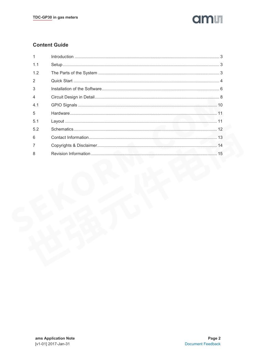
The figure below shows the general setup of the system.
Figure 1: General Setup
The gray colored unit is the external test board GP30Y – Gasmeter V1.1 which drives the ultrasonic
transducers for gas flow measuring applications. PicoProg and GP30-EVA-MODULE are the
standard products of ams.
1.2
The Parts of the System
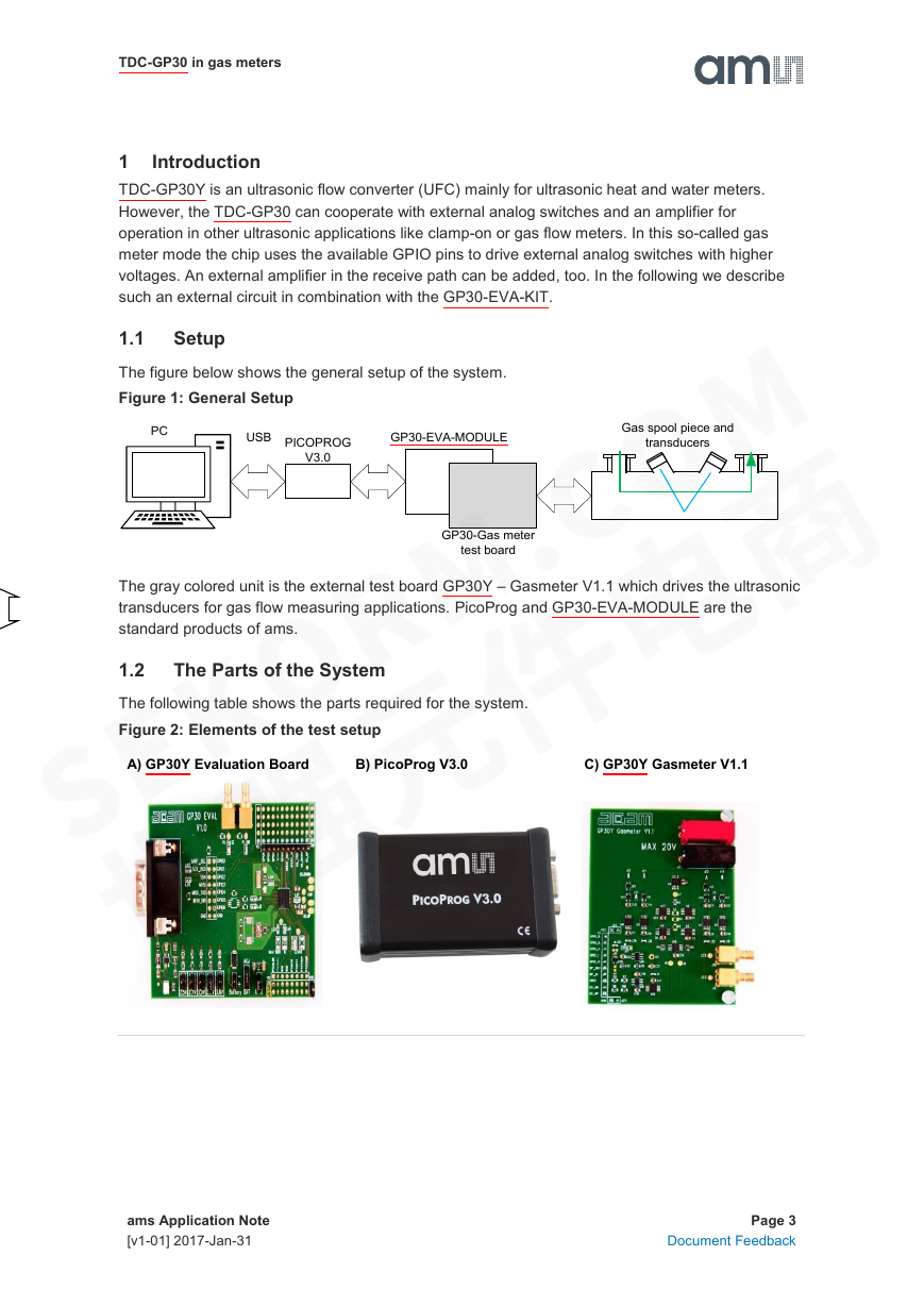
The following table shows the parts required for the system.
Figure 2: Elements of the test setup
A) GP30Y Evaluation Board
B) PicoProg V3.0
C) GP30Y Gasmeter V1.1
ams Application Note
[v1-01] 2017-Jan-31
Page 3
Document Feedback
USBPCPICOPROGV3.0GP30-EVA-MODULEGP30-Gas meter test boardGas spool piece and transducers�
TDC-GP30 in gas meters
2 Quick Start
1 First thing to do should be the installation of the system. Therefore, please first plug the
Gasmeter V1.1 on to the GP30-EVA-MODULE as it is shown in the figure below.
Figure 3: Connection of the Gasmeter V1.1 with the EVA-MODULE
2 Connect the PicoProg V3.0 (or V2.0, if you have an old one) to the EVA-MODULE. For the
moment do not connect the USB cable to the PC.
Figure 4: Connect PICOPROG
3 Now install of the ams GP30 evaluation software. For details see chapter 3. If the software
and PicoProg driver is already installed then you can skip this section and continue with
item 4.
4 Start the software and connect the PicoProg and the PC by means of the USB cable.
5 Click on System Reset button. The two indicators on the GIU, namely Pico Prog FW
Version and Comm. With GP30 OK? should now turn to green.
6 The next step is loading the configuration file and writing it to the GP30. Therefore, go to
File ► Open Config
Search for the specific configuration file for gas meter applications:
ams Application Note
[v1-01] 2017-Jan-31
Page 4
Document Feedback
�
TDC-GP30 in gas meters
GP30y_config_GasMeter_[Project Name].cfg
Caution! Never use configuration files other than for gas meters, as long as the gas meter
board is plugged and energized by external voltage.
7 Click on the Write Config button to write the configuration file into the TDC-GP30 chip.
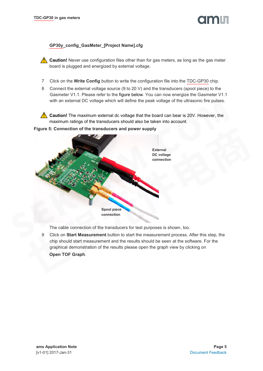
8 Connect the external voltage source (9 to 20 V) and the transducers (spool piece) to the
Gasmeter V1.1. Please refer to the figure below. You can now energize the Gasmeter V1.1
with an external DC voltage which will define the peak voltage of the ultrasonic fire pulses.
Caution! The maximum external dc voltage that the board can bear is 20V. However, the
maximum ratings of the transducers should also be taken into account.
Figure 5: Connection of the transducers and power supply
External
DC voltage
connection
Spool piece
connection
The cable connection of the transducers for test purposes is shown, too.
9 Click on Start Measurement button to start the measurement process. After this step, the
chip should start measurement and the results should be seen at the software. For the
graphical demonstration of the results please open the graph view by clicking on
Open TOF Graph.
ams Application Note
[v1-01] 2017-Jan-31
Page 5
Document Feedback
�
TDC-GP30 in gas meters
3
Installation of the Software
There is a set of files required for installation of the PicoProg and the GUI (Graphical User Interface)
of the development kit. The file structure is shown below and the steps to do the installation follow.
1 Open the directory (version 1.5.2 or newer) and the Volume
directory inside. Run Setup.exe (installer). Now select the installation path, recommended
is the default setting. Then click to “Next” and confirm the license agreement. After that, a
window appears that shows a summary of the software (includes the PicoProg driver) to be
installed. This part of the installation can take some minutes to complete.
2 Restart the computer.
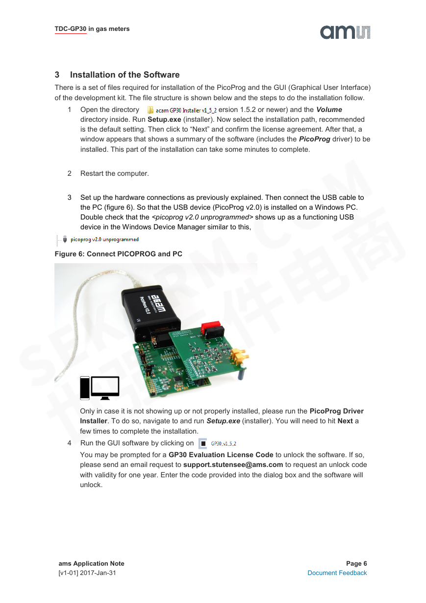
3 Set up the hardware connections as previously explained. Then connect the USB cable to
the PC (figure 6). So that the USB device (PicoProg v2.0) is installed on a Windows PC.
Double check that the
shows up as a functioning USB
device in the Windows Device Manager similar to this,
Figure 6: Connect PICOPROG and PC
Only in case it is not showing up or not properly installed, please run the PicoProg Driver
Installer. To do so, navigate to and run Setup.exe (installer). You will need to hit Next a
few times to complete the installation.
4 Run the GUI software by clicking on .
You may be prompted for a GP30 Evaluation License Code to unlock the software. If so,
please send an email request to support.stutensee@ams.com to request an unlock code
with validity for one year. Enter the code provided into the dialog box and the software will
unlock.
ams Application Note
[v1-01] 2017-Jan-31
Page 6
Document Feedback
�TDC-GP30 in gas meters
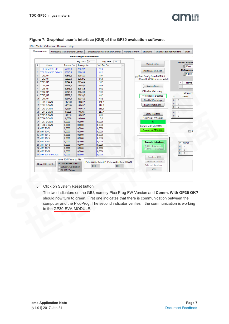
Figure 7: Graphical user’s interface (GUI) of the GP30 evaluation software.
5 Click on System Reset button.
The two indicators on the GIU, namely Pico Prog FW Version and Comm. With GP30 OK?
should now turn to green. First one indicates that there is communication between the
computer and the PicoProg. The second indicator verifies if the communication is working
to the GP30-EVA-MODULE.
ams Application Note
[v1-01] 2017-Jan-31
Page 7
Document Feedback
�
TDC-GP30 in gas meters
4 Circuit Design in Detail
The circuit design and the layout of the Gasmeter V1.1 can be seen in section 5.
Basically, the Gasmeter V1.1 is designed to send ultrasonic fire pulses that have relatively high
peak values and amplify the received signal to a value which is meaningful for the GP30. The circuit
was designed for development and test purposes, therefore there are many things added to
increase the flexibility, observability and immunity against other disturbances.
May be the number of devices used is also not quite as less as it could be. For instance the quantity
of some analog switches, e.g. U2 and U17, could be decreased to one, or instead of separate
housing 2 switches at one device could be used… However to decrease crosstalks and increase
the robustness such savings haven’t been done.
In the circuit the jumpers can be seen almost everywhere (J19, J20, J21, etc.). This was done for
the sake of flexibility. Because it makes it quite easy to separate certain parts from the whole circuit
and see its advantages/disadvantages to the system.
Moreover, the circuit has been equipped with some test points. So that it is easily observed what is
actually going on in that certain point of the circuit. On J5 and J6 the sent signal or the received
signal before the amplification can be seen. The amplified received signal can also be seen on J31.
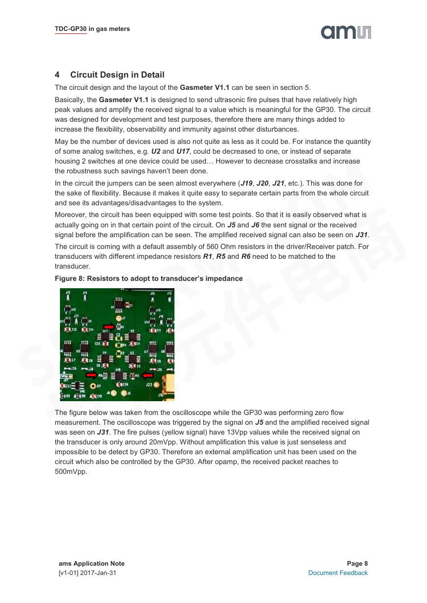
The circuit is coming with a default assembly of 560 Ohm resistors in the driver/Receiver patch. For
transducers with different impedance resistors R1, R5 and R6 need to be matched to the
transducer.
Figure 8: Resistors to adopt to transducer’s impedance
The figure below was taken from the oscilloscope while the GP30 was performing zero flow
measurement. The oscilloscope was triggered by the signal on J5 and the amplified received signal
was seen on J31. The fire pulses (yellow signal) have 13Vpp values while the received signal on
the transducer is only around 20mVpp. Without amplification this value is just senseless and
impossible to be detect by GP30. Therefore an external amplification unit has been used on the
circuit which also be controlled by the GP30. After opamp, the received packet reaches to
500mVpp.
ams Application Note
[v1-01] 2017-Jan-31
Page 8
Document Feedback
�




 2023年江西萍乡中考道德与法治真题及答案.doc
 2012年重庆南川中考生物真题及答案.doc
 2013年江西师范大学地理学综合及文艺理论基础考研真题.doc
 2020年四川甘孜小升初语文真题及答案I卷.doc
 2020年注册岩土工程师专业基础考试真题及答案.doc
 2023-2024学年福建省厦门市九年级上学期数学月考试题及答案.doc
 2021-2022学年辽宁省沈阳市大东区九年级上学期语文期末试题及答案.doc
 2022-2023学年北京东城区初三第一学期物理期末试卷及答案.doc
 2018上半年江西教师资格初中地理学科知识与教学能力真题及答案.doc
 2012年河北国家公务员申论考试真题及答案-省级.doc
 2020-2021学年江苏省扬州市江都区邵樊片九年级上学期数学第一次质量检测试题及答案.doc
 2022下半年黑龙江教师资格证中学综合素质真题及答案.doc