EURASIP Journal on Applied Signal Processing 2002:6, 622–634
c 2002 Hindawi Publishing Corporation
A Standard-Compliant Virtual Meeting System
with Active Video Object Tracking
Chia-Wen Lin
Department of Computer Science and Information Engineering, National Chung Cheng University, Chiayi 621, Taiwan
Email: cwlin@cs.ccu.edu.tw
Yao-Jen Chang
Department of Electrical Engineering, National Tsing Hua University, Hsinchu 300, Taiwan
Email: kc@benz.ee.nthu.edu.tw
Chih-Ming Wang
Department of Electrical Engineering, National Tsing Hua University, Hsinchu 300, Taiwan
Email: neil@benz.ee.nthu.edu.tw
Yung-Chang Chen
Department of Electrical Engineering, National Tsing Hua University, Hsinchu 300, Taiwan
Email: ycchen@ee.nthu.edu.tw
Ming-Ting Sun
Information Processing Laboratory, University of Washington, Seattle, WA 98195, USA
Email: sun@ee.washington.edu
Received 2 October 2001 and in revised form 24 March 2002
This paper presents an H.323 standard compliant virtual video conferencing system. The proposed system not only serves as a
multipoint control unit (MCU) for multipoint connection but also provides a gateway function between the H.323 LAN (local-
area network) and the H.324 WAN (wide-area network) users. The proposed virtual video conferencing system provides user-
friendly object compositing and manipulation features including 2D video object scaling, repositioning, rotation, and dynamic
bit-allocation in a 3D virtual environment. A reliable, and accurate scheme based on background image mosaics is proposed for
real-time extracting and tracking foreground video objects from the video captured with an active camera. Chroma-key insertion
is used to facilitate video objects extraction and manipulation. We have implemented a prototype of the virtual conference system
with an integrated graphical user interface to demonstrate the feasibility of the proposed methods.
Keywords and phrases: video conference, virtual meeting, immersive video conference, networked multimedia, multipoint con-
trol unit, MCU, multimedia over IP, object segmentation, object tracking.
INTRODUCTION
1.
With the rapid growth of multimedia signal processing and
communication, virtual meeting technologies are becoming
possible. A virtual meeting environment provides the re-
mote collaborators advanced human-to-computer or even
human-to-human interfaces so that scientists, engineers, and
businessmen can work and conduct business with each other
as if they were working face-to-face in the same environment.
The key technologies of virtual meeting can also be used in
many applications such as telepresence, remote collabora-
tion, distance learning, electronic commerce, entertainment,
Internet gaming, and so forth.
A virtual conferencing prototype, personal presence sys-
tem (PPS), which provides user presentation control (e.g.,
scaling, repositioning, etc.) was firstly proposed in [1, 2].
Due to the large computational demand, a powerful dedi-
cated hardware is required for supporting the virtual meet-
ing functionality, thereby leading to a high implementa-
tion cost. Recently, several works have been done with a fo-
cus on the development of avatar-based virtual conferenc-
ing systems. For example, a virtual chat room application, V-
Chat [3], has been developed to provide a 3D environment
with 2D cartoon-like characters, which is capable of send-
ing text messages and performing some predefined actions.
�
A Standard-Compliant Virtual Meeting System with Active Video Object Tracking
623
H.323
terminal
H.323
terminal
H.323
terminal
VCMCU
H.323
terminal
functions
Conversion
functions
(MC/MP)
H.324/l
terminal
functions
H.324/l
terminal
H.324/l
terminal
ISDN
...
ISDN
MP: multipoint processor
MC: multipoint controller
LAN
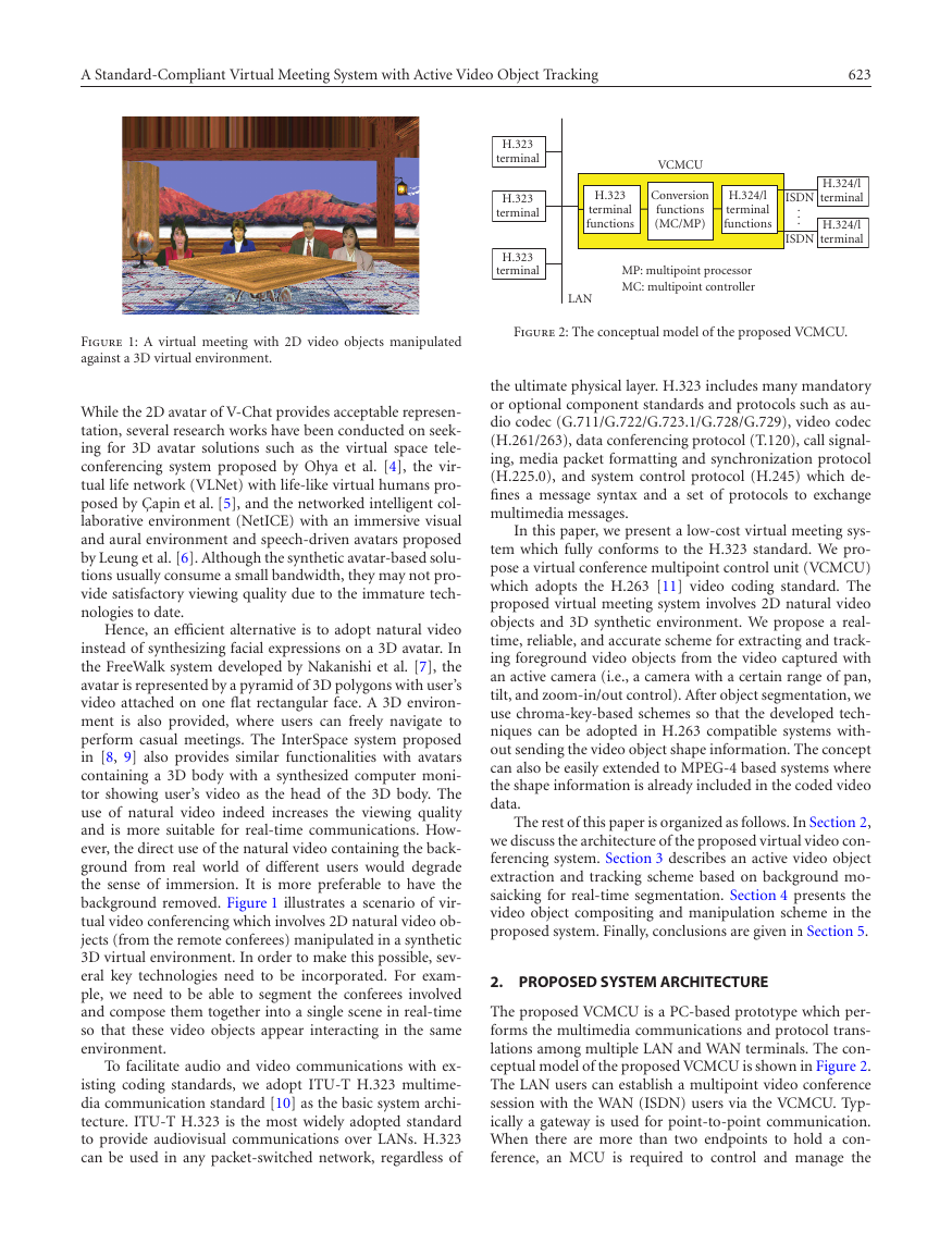
Figure 2: The conceptual model of the proposed VCMCU.
the ultimate physical layer. H.323 includes many mandatory
or optional component standards and protocols such as au-
dio codec (G.711/G.722/G.723.1/G.728/G.729), video codec
(H.261/263), data conferencing protocol (T.120), call signal-
ing, media packet formatting and synchronization protocol
(H.225.0), and system control protocol (H.245) which de-
fines a message syntax and a set of protocols to exchange
multimedia messages.
In this paper, we present a low-cost virtual meeting sys-
tem which fully conforms to the H.323 standard. We pro-
pose a virtual conference multipoint control unit (VCMCU)
which adopts the H.263 [11] video coding standard. The
proposed virtual meeting system involves 2D natural video
objects and 3D synthetic environment. We propose a real-
time, reliable, and accurate scheme for extracting and track-
ing foreground video objects from the video captured with
an active camera (i.e., a camera with a certain range of pan,
tilt, and zoom-in/out control). After object segmentation, we
use chroma-key-based schemes so that the developed tech-
niques can be adopted in H.263 compatible systems with-
out sending the video object shape information. The concept
can also be easily extended to MPEG-4 based systems where
the shape information is already included in the coded video
data.
The rest of this paper is organized as follows. In Section 2,
we discuss the architecture of the proposed virtual video con-
ferencing system. Section 3 describes an active video object
extraction and tracking scheme based on background mo-
saicking for real-time segmentation. Section 4 presents the
video object compositing and manipulation scheme in the
proposed system. Finally, conclusions are given in Section 5.
2. PROPOSED SYSTEM ARCHITECTURE
The proposed VCMCU is a PC-based prototype which per-
forms the multimedia communications and protocol trans-
lations among multiple LAN and WAN terminals. The con-
ceptual model of the proposed VCMCU is shown in Figure 2.
The LAN users can establish a multipoint video conference
session with the WAN (ISDN) users via the VCMCU. Typ-
ically a gateway is used for point-to-point communication.
When there are more than two endpoints to hold a con-
ference, an MCU is required to control and manage the
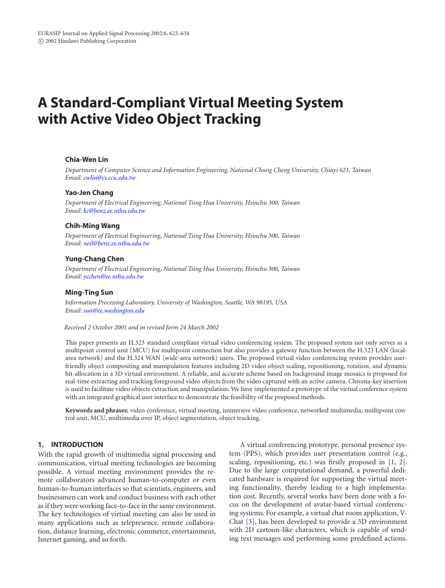
Figure 1: A virtual meeting with 2D video objects manipulated
against a 3D virtual environment.
While the 2D avatar of V-Chat provides acceptable represen-
tation, several research works have been conducted on seek-
ing for 3D avatar solutions such as the virtual space tele-
conferencing system proposed by Ohya et al. [4], the vir-
tual life network (VLNet) with life-like virtual humans pro-
posed by C¸ apin et al. [5], and the networked intelligent col-
laborative environment (NetICE) with an immersive visual
and aural environment and speech-driven avatars proposed
by Leung et al. [6]. Although the synthetic avatar-based solu-
tions usually consume a small bandwidth, they may not pro-
vide satisfactory viewing quality due to the immature tech-
nologies to date.
Hence, an efficient alternative is to adopt natural video
instead of synthesizing facial expressions on a 3D avatar. In
the FreeWalk system developed by Nakanishi et al. [7], the
avatar is represented by a pyramid of 3D polygons with user’s
video attached on one flat rectangular face. A 3D environ-
ment is also provided, where users can freely navigate to
perform casual meetings. The InterSpace system proposed
in [8, 9] also provides similar functionalities with avatars
containing a 3D body with a synthesized computer moni-
tor showing user’s video as the head of the 3D body. The
use of natural video indeed increases the viewing quality
and is more suitable for real-time communications. How-
ever, the direct use of the natural video containing the back-
ground from real world of different users would degrade
the sense of immersion. It is more preferable to have the
background removed. Figure 1 illustrates a scenario of vir-
tual video conferencing which involves 2D natural video ob-
jects (from the remote conferees) manipulated in a synthetic
3D virtual environment. In order to make this possible, sev-
eral key technologies need to be incorporated. For exam-
ple, we need to be able to segment the conferees involved
and compose them together into a single scene in real-time
so that these video objects appear interacting in the same
environment.
To facilitate audio and video communications with ex-
isting coding standards, we adopt ITU-T H.323 multime-
dia communication standard [10] as the basic system archi-
tecture. ITU-T H.323 is the most widely adopted standard
to provide audiovisual communications over LANs. H.323
can be used in any packet-switched network, regardless of
�
624
EURASIP Journal on Applied Signal Processing
H.323 client
Server (VCMCU)
H.324/l client
Vtalk323
Multipoint controller
Vtalk324/l
AV
codecs
G.711,
G.723.1,
H.263
T.120
datacom
System
control
H.245,
H.225.0
System control
H.245, H.225.0, H.223
Video
proc.
Audio
proc.
T.120
data
server
Session control
Session control
System
control
H.245,
H.223
T.120
data
AV
codecs
G.723.1,
H.263
LAN
ISDN
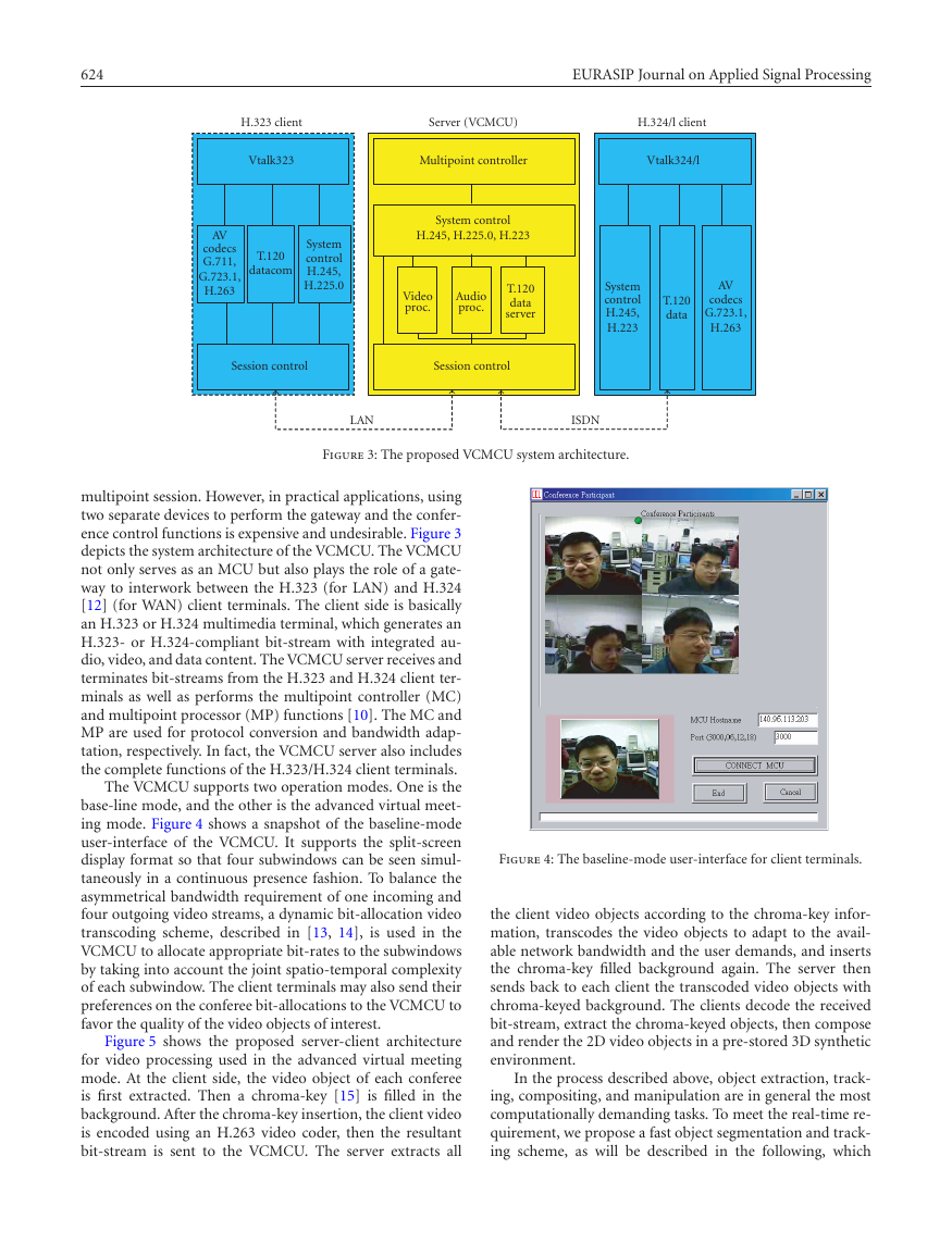
Figure 3: The proposed VCMCU system architecture.
multipoint session. However, in practical applications, using
two separate devices to perform the gateway and the confer-
ence control functions is expensive and undesirable. Figure 3
depicts the system architecture of the VCMCU. The VCMCU
not only serves as an MCU but also plays the role of a gate-
way to interwork between the H.323 (for LAN) and H.324
[12] (for WAN) client terminals. The client side is basically
an H.323 or H.324 multimedia terminal, which generates an
H.323- or H.324-compliant bit-stream with integrated au-
dio, video, and data content. The VCMCU server receives and
terminates bit-streams from the H.323 and H.324 client ter-
minals as well as performs the multipoint controller (MC)
and multipoint processor (MP) functions [10]. The MC and
MP are used for protocol conversion and bandwidth adap-
tation, respectively. In fact, the VCMCU server also includes
the complete functions of the H.323/H.324 client terminals.
The VCMCU supports two operation modes. One is the
base-line mode, and the other is the advanced virtual meet-
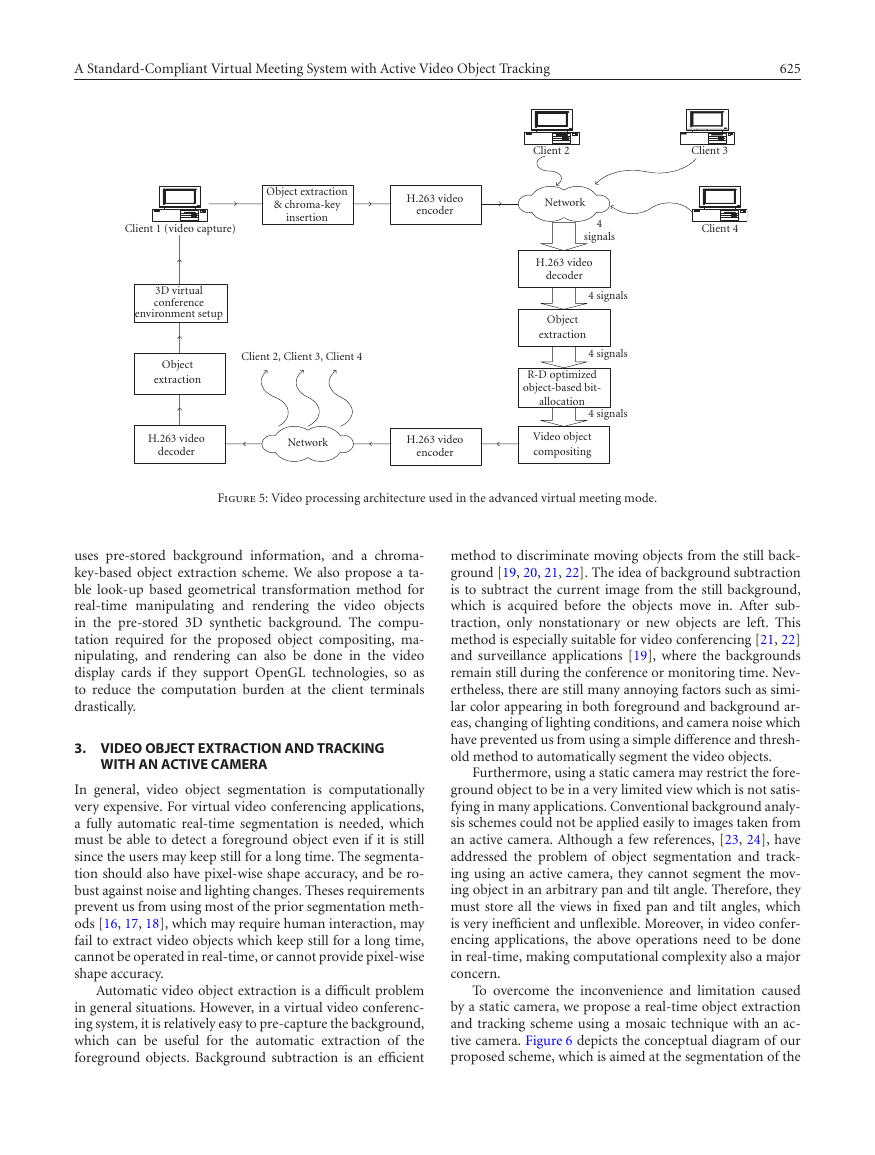
ing mode. Figure 4 shows a snapshot of the baseline-mode
user-interface of the VCMCU. It supports the split-screen
display format so that four subwindows can be seen simul-
taneously in a continuous presence fashion. To balance the
asymmetrical bandwidth requirement of one incoming and
four outgoing video streams, a dynamic bit-allocation video
transcoding scheme, described in [13, 14], is used in the
VCMCU to allocate appropriate bit-rates to the subwindows
by taking into account the joint spatio-temporal complexity
of each subwindow. The client terminals may also send their
preferences on the conferee bit-allocations to the VCMCU to
favor the quality of the video objects of interest.
Figure 5 shows the proposed server-client architecture
for video processing used in the advanced virtual meeting
mode. At the client side, the video object of each conferee
is first extracted. Then a chroma-key [15] is filled in the
background. After the chroma-key insertion, the client video
is encoded using an H.263 video coder, then the resultant
bit-stream is sent to the VCMCU. The server extracts all
Figure 4: The baseline-mode user-interface for client terminals.
the client video objects according to the chroma-key infor-
mation, transcodes the video objects to adapt to the avail-
able network bandwidth and the user demands, and inserts
the chroma-key filled background again. The server then
sends back to each client the transcoded video objects with
chroma-keyed background. The clients decode the received
bit-stream, extract the chroma-keyed objects, then compose
and render the 2D video objects in a pre-stored 3D synthetic
environment.
In the process described above, object extraction, track-
ing, compositing, and manipulation are in general the most
computationally demanding tasks. To meet the real-time re-
quirement, we propose a fast object segmentation and track-
ing scheme, as will be described in the following, which
�
A Standard-Compliant Virtual Meeting System with Active Video Object Tracking
625
Object extraction
& chroma-key
insertion
H.263 video
encoder
Client 2, Client 3, Client 4
Client 1 (video capture)
3D virtual
conference
environment setup
Object
extraction
Client 2
Client 3
Client 4
Network
4
signals
H.263 video
decoder
Object
extraction
4 signals
4 signals
R-D optimized
object-based bit-
allocation
4 signals
H.263 video
decoder
Network
H.263 video
encoder
Video object
compositing
Figure 5: Video processing architecture used in the advanced virtual meeting mode.
uses pre-stored background information, and a chroma-
key-based object extraction scheme. We also propose a ta-
ble look-up based geometrical transformation method for
real-time manipulating and rendering the video objects
in the pre-stored 3D synthetic background. The compu-
tation required for the proposed object compositing, ma-
nipulating, and rendering can also be done in the video
display cards if they support OpenGL technologies, so as
to reduce the computation burden at the client terminals
drastically.
3. VIDEO OBJECT EXTRACTION AND TRACKING
WITH AN ACTIVE CAMERA
In general, video object segmentation is computationally
very expensive. For virtual video conferencing applications,
a fully automatic real-time segmentation is needed, which
must be able to detect a foreground object even if it is still
since the users may keep still for a long time. The segmenta-
tion should also have pixel-wise shape accuracy, and be ro-
bust against noise and lighting changes. Theses requirements
prevent us from using most of the prior segmentation meth-
ods [16, 17, 18], which may require human interaction, may
fail to extract video objects which keep still for a long time,
cannot be operated in real-time, or cannot provide pixel-wise
shape accuracy.
Automatic video object extraction is a difficult problem
in general situations. However, in a virtual video conferenc-
ing system, it is relatively easy to pre-capture the background,
which can be useful for the automatic extraction of the
foreground objects. Background subtraction is an efficient
method to discriminate moving objects from the still back-
ground [19, 20, 21, 22]. The idea of background subtraction
is to subtract the current image from the still background,
which is acquired before the objects move in. After sub-
traction, only nonstationary or new objects are left. This
method is especially suitable for video conferencing [21, 22]
and surveillance applications [19], where the backgrounds
remain still during the conference or monitoring time. Nev-
ertheless, there are still many annoying factors such as simi-
lar color appearing in both foreground and background ar-
eas, changing of lighting conditions, and camera noise which
have prevented us from using a simple difference and thresh-
old method to automatically segment the video objects.
Furthermore, using a static camera may restrict the fore-
ground object to be in a very limited view which is not satis-
fying in many applications. Conventional background analy-
sis schemes could not be applied easily to images taken from
an active camera. Although a few references, [23, 24], have
addressed the problem of object segmentation and track-
ing using an active camera, they cannot segment the mov-
ing object in an arbitrary pan and tilt angle. Therefore, they
must store all the views in fixed pan and tilt angles, which
is very inefficient and unflexible. Moreover, in video confer-
encing applications, the above operations need to be done
in real-time, making computational complexity also a major
concern.
To overcome the inconvenience and limitation caused
by a static camera, we propose a real-time object extraction
and tracking scheme using a mosaic technique with an ac-
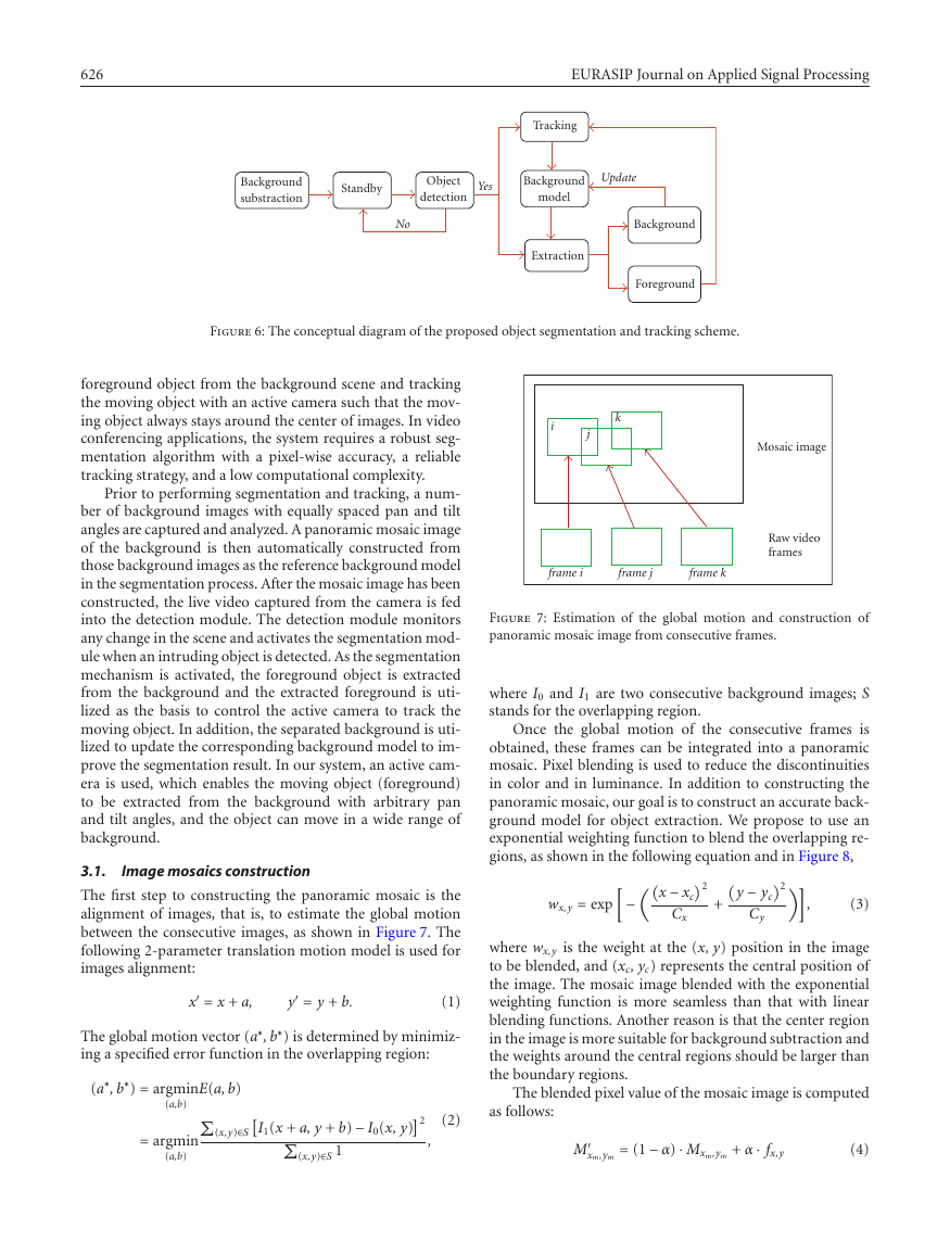
tive camera. Figure 6 depicts the conceptual diagram of our
proposed scheme, which is aimed at the segmentation of the
�
626
EURASIP Journal on Applied Signal Processing
Tracking
Background
substraction
Standby
Object
detection
Yes
Background
model
Update
No
Extraction
Background
Foreground
Figure 6: The conceptual diagram of the proposed object segmentation and tracking scheme.
foreground object from the background scene and tracking
the moving object with an active camera such that the mov-
ing object always stays around the center of images. In video
conferencing applications, the system requires a robust seg-
mentation algorithm with a pixel-wise accuracy, a reliable
tracking strategy, and a low computational complexity.
Prior to performing segmentation and tracking, a num-
ber of background images with equally spaced pan and tilt
angles are captured and analyzed. A panoramic mosaic image
of the background is then automatically constructed from
those background images as the reference background model
in the segmentation process. After the mosaic image has been
constructed, the live video captured from the camera is fed
into the detection module. The detection module monitors
any change in the scene and activates the segmentation mod-
ule when an intruding object is detected. As the segmentation
mechanism is activated, the foreground object is extracted
from the background and the extracted foreground is uti-
lized as the basis to control the active camera to track the
moving object. In addition, the separated background is uti-
lized to update the corresponding background model to im-
prove the segmentation result. In our system, an active cam-
era is used, which enables the moving object (foreground)
to be extracted from the background with arbitrary pan
and tilt angles, and the object can move in a wide range of
background.
Image mosaics construction
3.1.
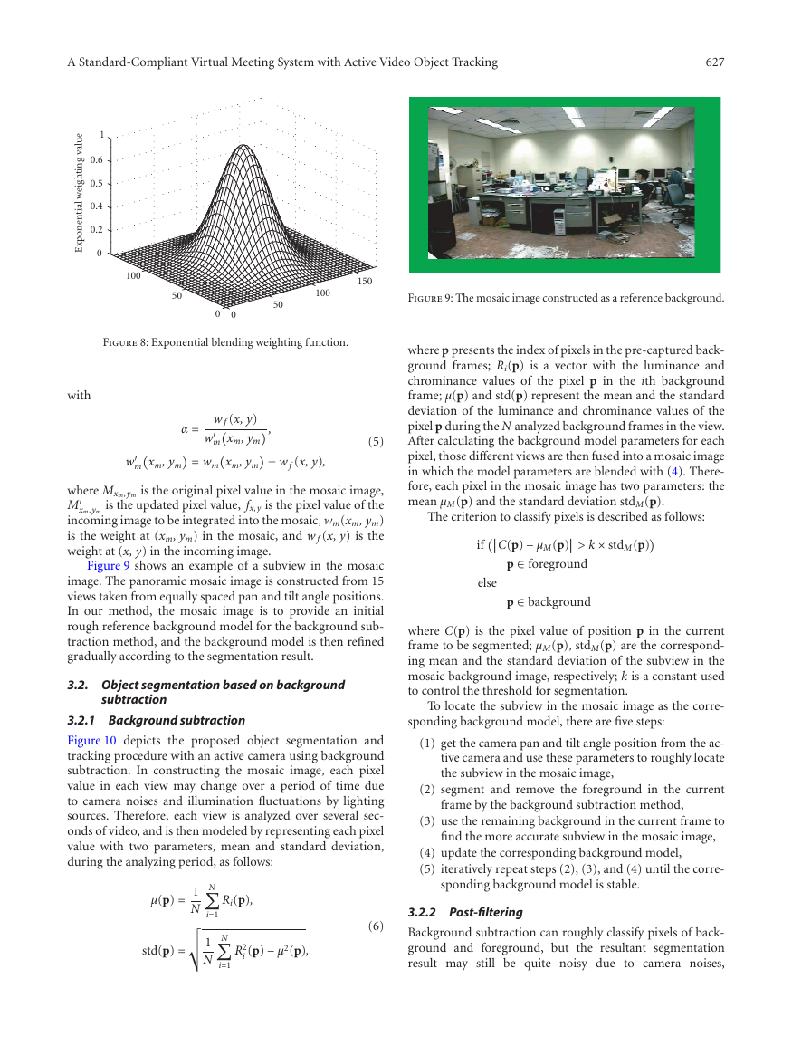
The first step to constructing the panoramic mosaic is the
alignment of images, that is, to estimate the global motion
between the consecutive images, as shown in Figure 7. The
following 2-parameter translation motion model is used for
images alignment:
x = x + a,
y = y + b.
(1)
) is determined by minimiz-
The global motion vector (a∗, b∗
ing a specified error function in the overlapping region:
(a∗, b∗
) = argmin
E(a, b)
(a,b)
I1(x + a, y + b) − I0(x, y)
(x,y)∈S
2
= argmin
(a,b)
(x,y)∈S 1
as follows:
(2)
,
M
xm,ym
= (1 − α) · Mxm,ym + α · fx,y
(4)
k
i
j
Mosaic image
Raw video
frames
frame i
frame j
frame k
Figure 7: Estimation of the global motion and construction of
panoramic mosaic image from consecutive frames.
where I0 and I1 are two consecutive background images; S
stands for the overlapping region.
Once the global motion of the consecutive frames is
obtained, these frames can be integrated into a panoramic
mosaic. Pixel blending is used to reduce the discontinuities
in color and in luminance. In addition to constructing the
panoramic mosaic, our goal is to construct an accurate back-
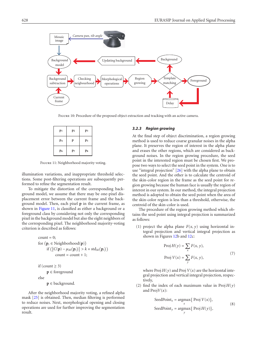
ground model for object extraction. We propose to use an
exponential weighting function to blend the overlapping re-
gions, as shown in the following equation and in Figure 8,
−
2
x − xc
Cx
y − yc
Cy
+
2
,
(3)
wx,y = exp
where wx,y is the weight at the (x, y) position in the image
to be blended, and (xc, yc) represents the central position of
the image. The mosaic image blended with the exponential
weighting function is more seamless than that with linear
blending functions. Another reason is that the center region
in the image is more suitable for background subtraction and
the weights around the central regions should be larger than
the boundary regions.
The blended pixel value of the mosaic image is computed
�
A Standard-Compliant Virtual Meeting System with Active Video Object Tracking
627
e
u
l
a
v
g
n
i
t
h
g
i
e
w
l
a
i
t
n
e
n
o
p
x
E
1
0.6
0.5
0.4
0.2
0
100
50
150
100
50
0
0
Figure 8: Exponential blending weighting function.
with
w
m
α =
w f (x, y)
w
xm, ym
m
= wm
xm, ym
,
xm, ym
+ w f (x, y),
(5)
where Mxm,ym is the original pixel value in the mosaic image,
M
xm,ym is the updated pixel value, fx,y is the pixel value of the
incoming image to be integrated into the mosaic, wm(xm, ym)
is the weight at (xm, ym) in the mosaic, and w f (x, y) is the
weight at (x, y) in the incoming image.
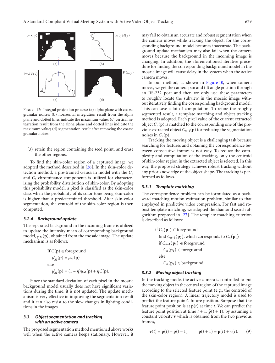
Figure 9 shows an example of a subview in the mosaic
image. The panoramic mosaic image is constructed from 15
views taken from equally spaced pan and tilt angle positions.
In our method, the mosaic image is to provide an initial
rough reference background model for the background sub-
traction method, and the background model is then refined
gradually according to the segmentation result.
3.2. Object segmentation based on background
subtraction
3.2.1 Background subtraction
Figure 10 depicts the proposed object segmentation and
tracking procedure with an active camera using background
subtraction. In constructing the mosaic image, each pixel
value in each view may change over a period of time due
to camera noises and illumination fluctuations by lighting
sources. Therefore, each view is analyzed over several sec-
onds of video, and is then modeled by representing each pixel
value with two parameters, mean and standard deviation,
during the analyzing period, as follows:
µ(p) = 1
N
Ri(p),
N
1
N
i=1
N
i=1
std(p) =
i (p) − µ2(p),
R2
Figure 9: The mosaic image constructed as a reference background.
where p presents the index of pixels in the pre-captured back-
ground frames; Ri(p) is a vector with the luminance and
chrominance values of the pixel p in the ith background
frame; µ(p) and std(p) represent the mean and the standard
deviation of the luminance and chrominance values of the
pixel p during the N analyzed background frames in the view.
After calculating the background model parameters for each
pixel, those different views are then fused into a mosaic image
in which the model parameters are blended with (4). There-
fore, each pixel in the mosaic image has two parameters: the
mean µM(p) and the standard deviation stdM(p).
The criterion to classify pixels is described as follows:
C(p) − µM(p)
> k × stdM(p)
if
p ∈ foreground
else
p ∈ background
where C(p) is the pixel value of position p in the current
frame to be segmented; µM(p), stdM(p) are the correspond-
ing mean and the standard deviation of the subview in the
mosaic background image, respectively; k is a constant used
to control the threshold for segmentation.
To locate the subview in the mosaic image as the corre-
sponding background model, there are five steps:
(1) get the camera pan and tilt angle position from the ac-
tive camera and use these parameters to roughly locate
the subview in the mosaic image,
(2) segment and remove the foreground in the current
frame by the background subtraction method,
(3) use the remaining background in the current frame to
find the more accurate subview in the mosaic image,
(4) update the corresponding background model,
(5) iteratively repeat steps (2), (3), and (4) until the corre-
sponding background model is stable.
(6)
3.2.2 Post-filtering
Background subtraction can roughly classify pixels of back-
ground and foreground, but the resultant segmentation
result may still be quite noisy due to camera noises,
�
628
EURASIP Journal on Applied Signal Processing
Camera pan, tilt angle
Mosaic
image
Background
model
Updating background
Background
Background
subtraction
Checking
neigbourhood
Morphological
operations
Region
growing
Template
matching
Foreground
Current
frame
Delay
Figure 10: Procedure of the proposed object extraction and tracking with an active camera.
p1
p4
p6
p2
p
p7
p3
p5
p8
Figure 11: Neighborhood majority voting.
illumination variations, and inappropriate threshold selec-
tions. Some post-filtering operations are subsequently per-
formed to refine the segmentation result.
To mitigate the distortion of the corresponding back-
ground model, we assume that there may be one-pixel dis-
placement error between the current frame and the back-
ground model. Then, each pixel p in the current frame, as
shown in Figure 11, is classified as either a background or a
foreground class by considering not only the corresponding
pixel in the background model but also the eight neighbors of
the corresponding pixel. The neighborhood majority-voting
criterion is described as follows:
count = 0;
for
> k × stdM
pi ∈ Neighborhood(p)
if
C(p) − µM
pi
pi
count = count + 1;
if (count ≥ 3)
p ∈ foreground
p ∈ background.
else
After the neighborhood majority voting, a refined alpha
mask [25] is obtained. Then, median filtering is performed
to reduce noises. Next, morphological opening and closing
operations are used for further improving the segmentation
result.
3.2.3 Region growing
At the final step of object discrimination, a region growing
method is used to reduce coarse granular noises in the alpha
plane. It preserves the region of interest in the alpha plane
and erases the other regions, which are considered as back-
ground noises. In the region growing procedure, the seed
point in the interested region must be chosen first. We pro-
pose two ways to select the seed point in the system. One is to
use “integral projection” [26] with the alpha plane to obtain
the seed point. And the other is to calculate the centroid of
the skin-color region in the frame as the seed point for re-
gion growing because the human face is usually the region of
interest in our system. In our method, the integral projection
method is adopted to obtain the seed point when the area of
the skin-color region is less than a threshold, otherwise, the
centroid of the skin-color is used.
The procedure of the region growing method which ob-
tains the seed point using integral projection is summarized
as follows:
(1) project the alpha plane F(x, y) using horizontal in-
tegral projection and vertical integral projection as
shown in Figures 12b and 12c:
Proj H(y) =
Proj V(x) =
F(x, y),
F(x, y),
(7)
x
y
where Proj H(y) and Proj V(x) are the horizontal inte-
gral projection and vertical integral projection, respec-
tively,
(2) find the index of each maximum value in Proj H(y)
and ProjV(x):
SeedPointx = argmax
SeedPointy = argmax
x
y
Proj V(x)
Proj H(y)
,
(8)
,
�
A Standard-Compliant Virtual Meeting System with Active Video Object Tracking
629
may fail to obtain an accurate and robust segmentation when
the camera moves while tracking the object, for the corre-
sponding background model becomes inaccurate. The back-
ground update mechanism may also fail when the camera
moves because the background in the incoming image is
changing. In addition, the aforementioned iterative proce-
dure for finding the corresponding background model in the
mosaic image will cause delay in the system when the active
camera moves.
In our method, as shown in Figure 10, when camera
moves, we get the camera pan and tilt angle position through
an RS-232 port and then we only use these parameters
to roughly locate the subview in the mosaic image with-
out iteratively finding the corresponding background model.
This can save a lot of computation. To refine the roughly
segmented result, a template matching and object tracking
method is adopted. Each pixel value of the current extracted
object Cn(p) is matched to the corresponding one of the pre-
vious extracted object Cn−1(p) for reducing the segmentation
noises in Cn(p).
Tracking the moving object is a challenging task because
searching for features and obtaining the correspondence be-
tween consecutive frames is not easy. To reduce the com-
plexity and computation of the tracking, only the centroid
of skin-color region in the extracted object is selected. In this
way, the proposed strategy achieves robust tracking without
any prior knowledge of the object shape. The tracking is per-
formed as follows.
3.3.1 Template matching
The correspondence problem can be formulated as a back-
ward matching motion estimation problem, similar to that
employed in predictive video compression. For fast and ro-
bust template matching, we adopted the diamond search al-
gorithm proposed in [27]. The template matching criterion
is described as follows:
if Cn
p1
∈ foreground
∈ foreground
∈ foreground
∈ background
find Cn−1
if Cn−1
p2
Cn
p1
else
Cn
p2
p1
, which corresponds to Cn
p1
F(x, y)
Proj H(y)
Proj V(x)
(a)
(c)
(b)
F
(x, y)
(d)
Figure 12: Integral projection process: (a) alpha plane with coarse
granular noises; (b) horizontal integration result from the alpha
plane and dotted lines indicate the maximum value; (c) vertical in-
tegration result from the alpha plane and dotted lines indicate the
maximum value; (d) segmentation result after removing the coarse
granular noises.
(3) retain the region containing the seed point, and erase
the other regions.
To find the skin-color region of a captured image, we
adopted the method described in [26]. In the skin-color de-
tection method, a pre-trained Gaussian model with the Cb
and Cr chrominance components is utilized for character-
izing the probability distribution of skin-color. By adopting
this probability model, a pixel is classified as the skin-color
class when the probability of its color tone being skin-color
is higher than a predetermined threshold. After skin-color
segmentation, the centroid of the skin-color region is then
computed.
3.2.4 Background update
The separated background in the incoming frame is utilized
to update the intensity mean of corresponding background
model, µM(p), obtained from the mosaic image. The update
mechanism is as follows:
If C(p) ∈ foreground
µ
M(p) = µM(p)
else
M(p) = (1 − η)µM(p) + ηC(p).
µ
Since the standard deviation of each pixel in the mosaic
background model usually does not have significant varia-
tions during the time, it is not updated. The update mech-
anism is very effective in improving the segmentation result
and it can also resist to the slow changes in lighting condi-
tions in the images.
3.3. Object segmentation and tracking
with an active camera
3.3.2 Moving object tracking
In the tracking mode, the active camera is controlled to put
the moving object in the central region of the captured image
according to the selected feature point (e.g., the centroid of
the skin-color region). A linear trajectory model is used to
predict the feature point’s future position. Suppose that the
feature point position is at p(t) at time t. We can predict the
feature point position at time t + 1,p(t + 1), by assuming a
constant velocity v which is obtained from the two previous
frames,
p(t + 1) = p(t) + ν(t).
(9)
The proposed segmentation method mentioned above works
well when the active camera keeps stationary. However, it
ν(t) = p(t) − p(t − 1),
�


 2023年江西萍乡中考道德与法治真题及答案.doc
 2012年重庆南川中考生物真题及答案.doc
 2013年江西师范大学地理学综合及文艺理论基础考研真题.doc
 2020年四川甘孜小升初语文真题及答案I卷.doc
 2020年注册岩土工程师专业基础考试真题及答案.doc
 2023-2024学年福建省厦门市九年级上学期数学月考试题及答案.doc
 2021-2022学年辽宁省沈阳市大东区九年级上学期语文期末试题及答案.doc
 2022-2023学年北京东城区初三第一学期物理期末试卷及答案.doc
 2018上半年江西教师资格初中地理学科知识与教学能力真题及答案.doc
 2012年河北国家公务员申论考试真题及答案-省级.doc
 2020-2021学年江苏省扬州市江都区邵樊片九年级上学期数学第一次质量检测试题及答案.doc
 2022下半年黑龙江教师资格证中学综合素质真题及答案.doc