Overhead Transparencies for
Analog Design Environment
Training Manual
Version 5.0
Education Services
September 30, 2002
�
Module 1: Introduction to ADE 5.0
Topics in this module
I Course objectives
I Course outline
I Class schedule
I Getting help, technical support, and documentation
I The Design Framework II Design Environment
I Accessing design tools
I Creating a library
I Creating cells and cell views
I Schematic capture
I Analog simulation
I Analyses
I Summary
�
Introduction to ADE 5.0
1-3
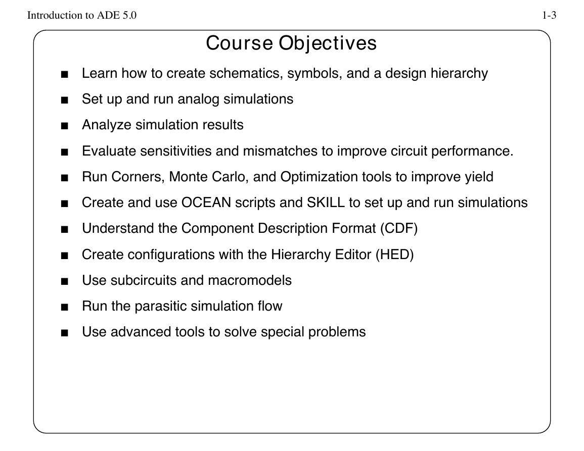
Course Objectives
I Learn how to create schematics, symbols, and a design hierarchy
I Set up and run analog simulations
I Analyze simulation results
I Evaluate sensitivities and mismatches to improve circuit performance.
I Run Corners, Monte Carlo, and Optimization tools to improve yield
I Create and use OCEAN scripts and SKILL to set up and run simulations
I Understand the Component Description Format (CDF)
I Create configurations with the Hierarchy Editor (HED)
I Use subcircuits and macromodels
I Run the parasitic simulation flow
I Use advanced tools to solve special problems
�
Introduction to ADE 5.0
1-5
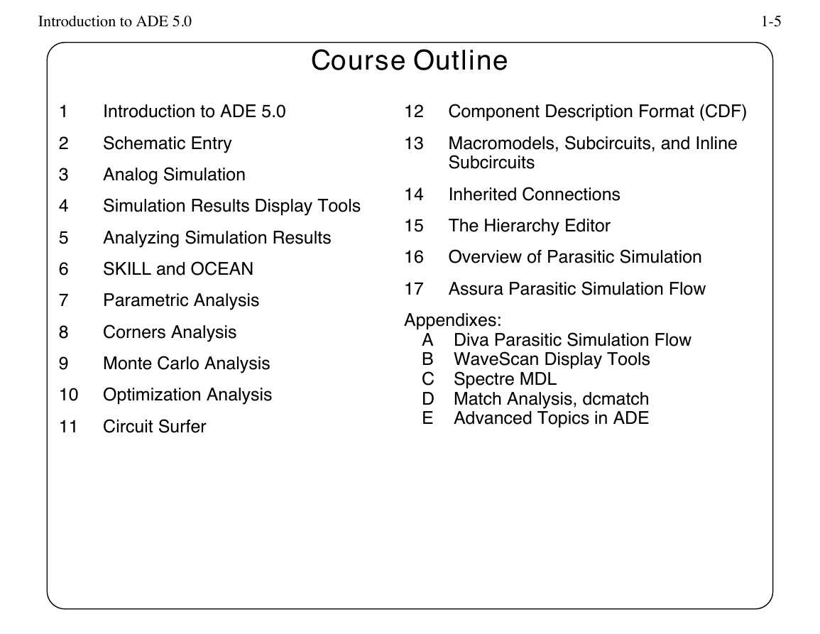
Course Outline
Introduction to ADE 5.0
12 Component Description Format (CDF)
13 Macromodels, Subcircuits, and Inline
Subcircuits
14
15
Inherited Connections
The Hierarchy Editor
16 Overview of Parasitic Simulation
17
Assura Parasitic Simulation Flow
Appendixes:
A Diva Parasitic Simulation Flow
B WaveScan Display Tools
C Spectre MDL
D Match Analysis, dcmatch
E Advanced Topics in ADE
1
2
3
4
5
6
7
8
9
Schematic Entry
Analog Simulation
Simulation Results Display Tools
Analyzing Simulation Results
SKILL and OCEAN
Parametric Analysis
Corners Analysis
Monte Carlo Analysis
10 Optimization Analysis
11 Circuit Surfer
�
Introduction to ADE 5.0
1-7
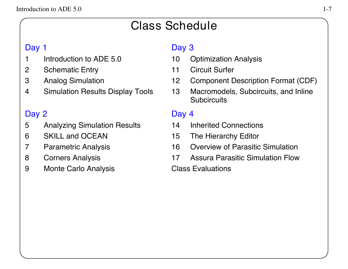
Class Schedule
Day 1
1
2
3
4
Introduction to ADE 5.0
Schematic Entry
Analog Simulation
Simulation Results Display Tools
Day 2
5
6
7
8
9
Analyzing Simulation Results
SKILL and OCEAN
Parametric Analysis
Corners Analysis
Monte Carlo Analysis
Day 3
10 Optimization Analysis
11 Circuit Surfer
12 Component Description Format (CDF)
13 Macromodels, Subcircuits, and Inline
Subcircuits
Inherited Connections
The Hierarchy Editor
Day 4
14
15
16 Overview of Parasitic Simulation
17
Assura Parasitic Simulation Flow
Class Evaluations
�
Introduction to ADE 5.0
1-9
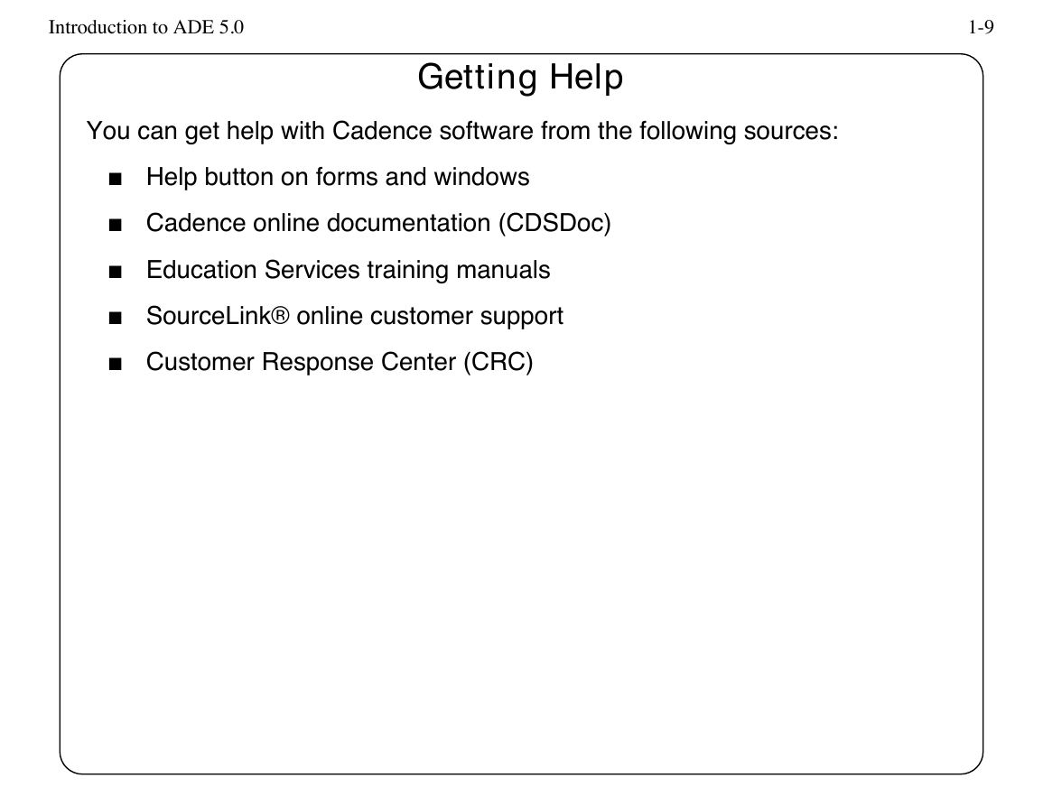
You can get help with Cadence software from the following sources:
Getting Help
I Help button on forms and windows
I Cadence online documentation (CDSDoc)
I Education Services training manuals
I SourceLink® online customer support
I Customer Response Center (CRC)
�
Introduction to ADE 5.0
1-11
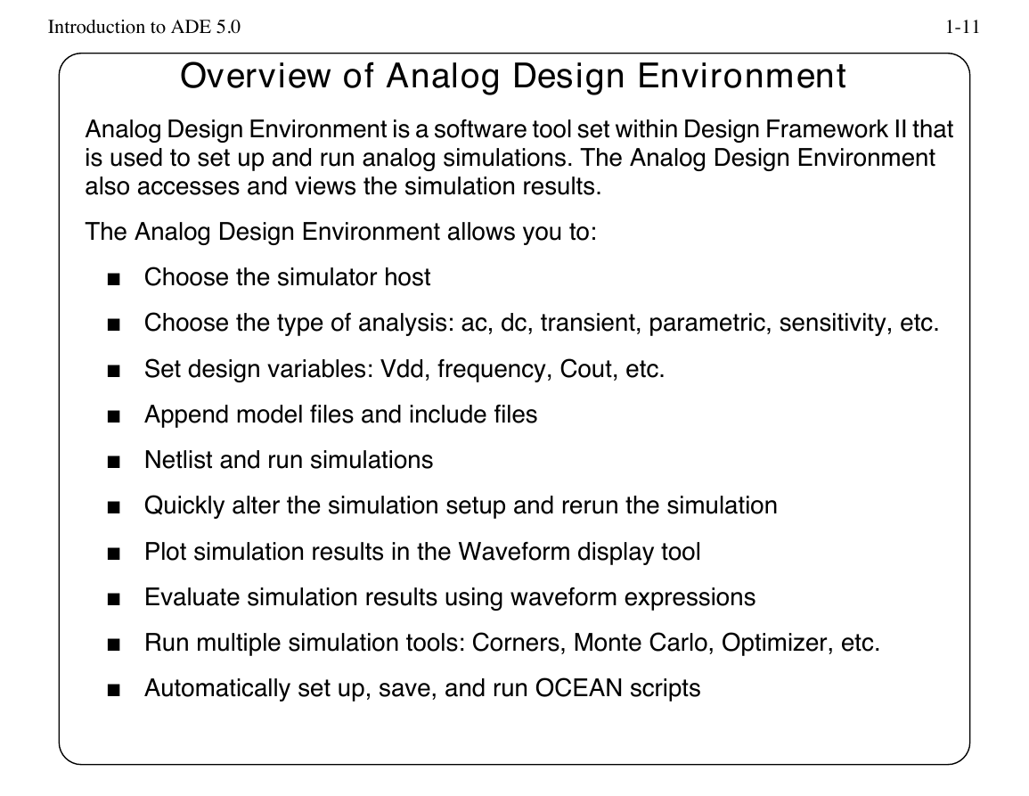
Overview of Analog Design Environment
Analog Design Environment is a software tool set within Design Framework II that
is used to set up and run analog simulations. The Analog Design Environment
also accesses and views the simulation results.
The Analog Design Environment allows you to:
I Choose the simulator host
I Choose the type of analysis: ac, dc, transient, parametric, sensitivity, etc.
I Set design variables: Vdd, frequency, Cout, etc.
I Append model files and include files
I Netlist and run simulations
I Quickly alter the simulation setup and rerun the simulation
I Plot simulation results in the Waveform display tool
I Evaluate simulation results using waveform expressions
I Run multiple simulation tools: Corners, Monte Carlo, Optimizer, etc.
I Automatically set up, save, and run OCEAN scripts
�
Introduction to ADE 5.0
1-13
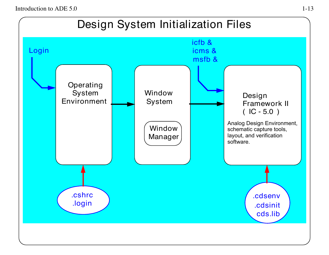
Design System Initialization Files
Login
icfb &
icms &
msfb &
Operating
System
Environment
Window
System
Window
Manager
Design
Framework II
( IC - 5.0 )
Analog Design Environment,
schematic capture tools,
layout, and verification
software.
.cshrc
.login
.cdsenv
.cdsinit
cds.lib
�



 2023年江西萍乡中考道德与法治真题及答案.doc
 2012年重庆南川中考生物真题及答案.doc
 2013年江西师范大学地理学综合及文艺理论基础考研真题.doc
 2020年四川甘孜小升初语文真题及答案I卷.doc
 2020年注册岩土工程师专业基础考试真题及答案.doc
 2023-2024学年福建省厦门市九年级上学期数学月考试题及答案.doc
 2021-2022学年辽宁省沈阳市大东区九年级上学期语文期末试题及答案.doc
 2022-2023学年北京东城区初三第一学期物理期末试卷及答案.doc
 2018上半年江西教师资格初中地理学科知识与教学能力真题及答案.doc
 2012年河北国家公务员申论考试真题及答案-省级.doc
 2020-2021学年江苏省扬州市江都区邵樊片九年级上学期数学第一次质量检测试题及答案.doc
 2022下半年黑龙江教师资格证中学综合素质真题及答案.doc