logo资料库

Modbus Protocol Reference Guide.pdf

第1页 / 共36页
第2页 / 共36页
第3页 / 共36页
第4页 / 共36页
第5页 / 共36页
第6页 / 共36页
第7页 / 共36页
第8页 / 共36页
资料共36页,剩余部分请下载后查看
Contents
1. Introduction
2. Modbus Protocol
2.1 General Description
2.2 Modbus Message Framing
ASCII Framing
RTU Framing
Address Field
Function Field
Data Field
Error Checking Field
LRC Checking
CRC Checking
2.3 Modbus Function Formats
Data Address
Coil
Input Status
Input Register
Holding Register
2.4 Field Contents in Modbus Messages
3. Modbus Function Codes
3.1 Read Coil Status (01)
3.2 Read Input Status (02)
3.3 Read Holding Register (03)
3.4 Read Input Register (04)
3.5 Force Single Coil (05)
3.6 Preset Single Register (06)
3.7 Diagnostics (08)
3.8 Fetch Communication Event Counter (11, 0x0B)
3.9 Fetch Communication Event Log (12, 0x0C)
3.10 Force Multiple Coils (15, 0x0F)
3.11 Preset Multiple Registers (16, 0x10)
3.12 Report Slave ID (17, 0x11)
4. Diagnostic Subfunctions (08)
4.1 Return Query Data (00)
4.2 Restart Communications Option (01)
4.3 Return Diagnostics Register (02)
4.4 Force Listen Only Mode (04)
4.5 Clear Counters and Diagnostic Register (10, 0x0A)
4.6 Return Bus Message Count (11, 0x0B)
4.7 Return Bus Communication Error Count (12, 0x0C)
4.8 Return Bus Exception Error Count (13, 0x0D)
4.9 Return Slave Message Count (14, 0x0E)
4.10 Return Slave No Response Count (15, 0x0F)
4.11 Return Slave Busy Count (17, 0x11)
4.12 Return Bus Character Overrun Count (18, 0x12)
5. Exception Responses
Appendix A. R1M Series Remote I/O Modbus Communications
A-1 Function Codes
A-2 Data Addresses
A-3 Input Data
A-4 Coils (DO) Description
DO (1 – 32)
Cold Junction Compensation SW (33 – 48)
A-5 Input Status (DI) Description
DI (10001 – 10032)
ADC Overrange (10033 – 10048)
A-6 Input Registers Description
Analog Input in % (30001 – 30016)
Analog Input in Engineering Unit (30017 – 30048)
Cold Junction Temperature (30049 – 30050)
Channel Status (30081 – 30096)
System Status (30513)
Model No. (30514 – 30521)
Serial No. (30522 – 30529)
Hardware Version No. (30530 – 30537)
Firmware Version No. (30538 – 30545)
A-7 Holding Registers Description
Analog Output in % (40001 – 40016)
Analog Output in Engineering Unit (40017 – 40048)
I/O Type No. (40145 – 40160)
Burnout Type (40161 – 40176)
Appendix B. R2M Remote I/O Modbus Communications
B-1 Function Codes
B-2 Data Addresses
B-3 Input Data
B-4 Coils (DO) Description
DO (1 – 32)
Cold Junction Compensation SW (33 – 40)
B-5 Input Status (DI) Description
DI (10001 – 10032)
ADC Overrange (10033 – 10040)
B-6 Input Registers Description
Analog Input in Engineering Unit (30017 – 30032)
Cold Junction Temperature (30049 – 30050)
Channel Status (30081 – 30088)
System Status (30513)
Model No. (30514 – 30521)
Serial No. (30522 – 30529)
Hardware Version No. (30530 – 30537)
Firmware Version No. (30538 – 30545)
B-7 Holding Registers Description
Input Filter Time Constant (40049 – 40050)
Input Type No. (40145 – 40152)
Burnout Type (40514)
Appendix C. Modbus TCP/IP Protocol
C-1 Introduction
C-2 Protocol Layout
C-3 Example
C-4 Point of Caution
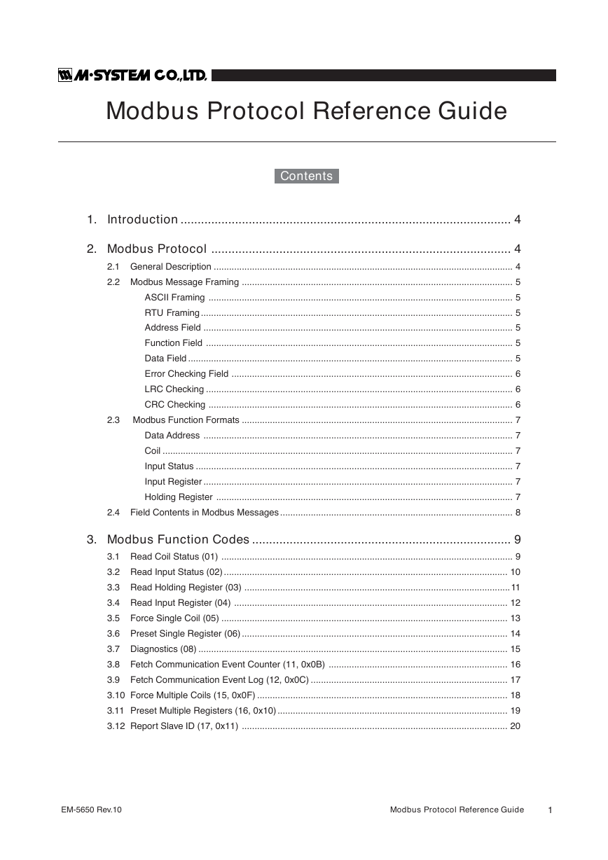
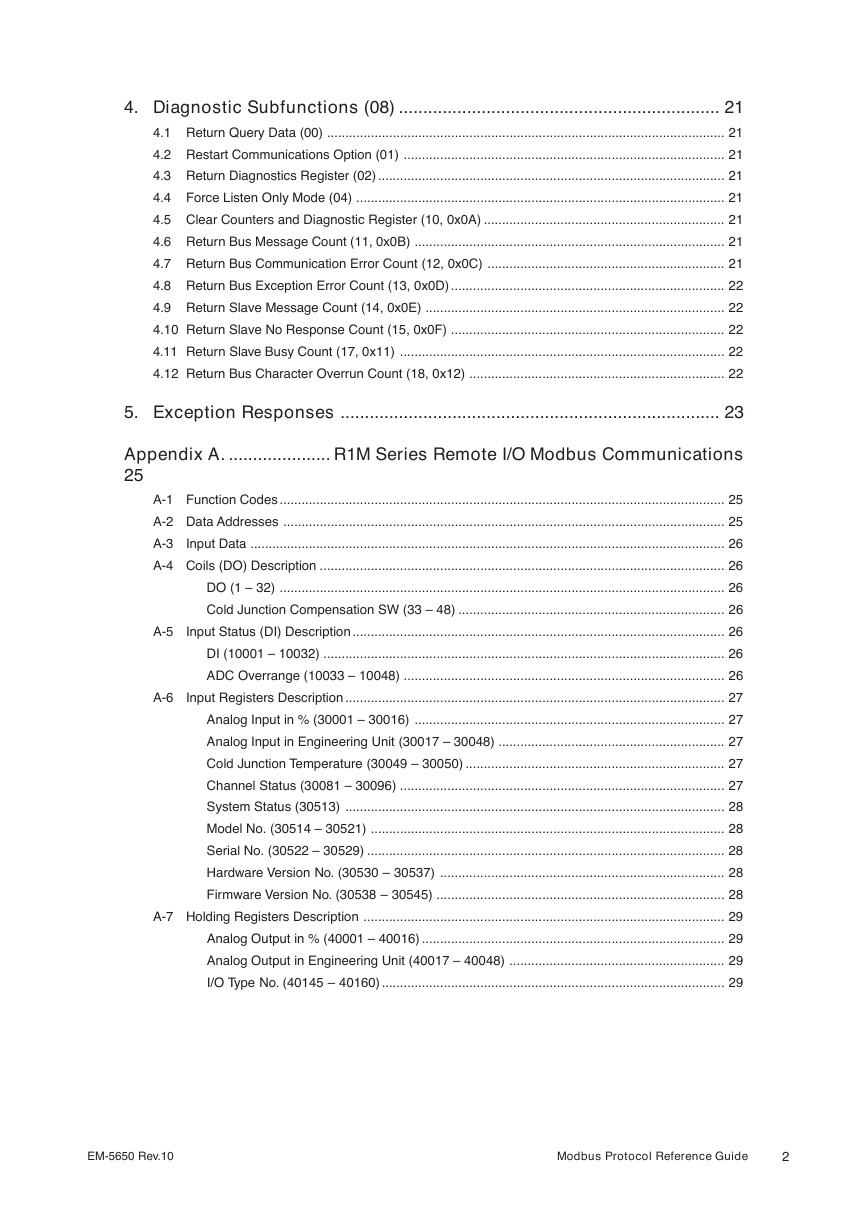
Modbus Protocol Reference Guide Contents 1. Introduction ................................................................................................. 4 2. Modbus Protocol ........................................................................................ 4 2.1 General Description ..................................................................................................................... 4 2.2 Modbus Message Framing .......................................................................................................... 5 ASCII Framing ....................................................................................................................... 5 RTU Framing .......................................................................................................................... 5 Address Field ......................................................................................................................... 5 Function Field ........................................................................................................................ 5 Data Field ............................................................................................................................... 5 Error Checking Field .............................................................................................................. 6 LRC Checking ........................................................................................................................ 6 CRC Checking ....................................................................................................................... 6 Modbus Function Formats .......................................................................................................... 7 Data Address ......................................................................................................................... 7 Coil ......................................................................................................................................... 7 Input Status ............................................................................................................................ 7 Input Register ......................................................................................................................... 7 Holding Register .................................................................................................................... 7 2.4 Field Contents in Modbus Messages ........................................................................................... 8 2.3 3. Modbus Function Codes ............................................................................ 9 3.1 Read Coil Status (01) .................................................................................................................. 9 3.2 Read Input Status (02) ............................................................................................................... 10 3.3 Read Holding Register (03) ........................................................................................................11 3.4 Read Input Register (04) ........................................................................................................... 12 3.5 Force Single Coil (05) ................................................................................................................ 13 3.6 Preset Single Register (06) ........................................................................................................ 14 3.7 Diagnostics (08) ......................................................................................................................... 15 3.8 Fetch Communication Event Counter (11, 0x0B) ...................................................................... 16 3.9 Fetch Communication Event Log (12, 0x0C) ............................................................................. 17 3.10 Force Multiple Coils (15, 0x0F) .................................................................................................. 18 3.11 Preset Multiple Registers (16, 0x10) .......................................................................................... 19 3.12 Report Slave ID (17, 0x11) ........................................................................................................ 20 EM-5650 Rev.10 Modbus Protocol Reference Guide 1
4. Diagnostic Subfunctions (08) .................................................................. 21 4.1 Return Query Data (00) ............................................................................................................. 21 4.2 Restart Communications Option (01) ........................................................................................ 21 4.3 Return Diagnostics Register (02) ............................................................................................... 21 4.4 Force Listen Only Mode (04) ..................................................................................................... 21 4.5 Clear Counters and Diagnostic Register (10, 0x0A) .................................................................. 21 4.6 Return Bus Message Count (11, 0x0B) ..................................................................................... 21 4.7 Return Bus Communication Error Count (12, 0x0C) ................................................................. 21 4.8 Return Bus Exception Error Count (13, 0x0D) ........................................................................... 22 4.9 Return Slave Message Count (14, 0x0E) .................................................................................. 22 4.10 Return Slave No Response Count (15, 0x0F) ........................................................................... 22 4.11 Return Slave Busy Count (17, 0x11) ......................................................................................... 22 4.12 Return Bus Character Overrun Count (18, 0x12) ...................................................................... 22 5. Exception Responses .............................................................................. 23 Appendix A. ..................... R1M Series Remote I/O Modbus Communications 25 A-1 Function Codes .......................................................................................................................... 25 A-2 Data Addresses ......................................................................................................................... 25 A-3 Input Data .................................................................................................................................. 26 A-4 Coils (DO) Description ............................................................................................................... 26 DO (1 – 32) .......................................................................................................................... 26 Cold Junction Compensation SW (33 – 48) ......................................................................... 26 A-5 Input Status (DI) Description ...................................................................................................... 26 DI (10001 – 10032) .............................................................................................................. 26 ADC Overrange (10033 – 10048) ........................................................................................ 26 A-6 Input Registers Description ........................................................................................................ 27 Analog Input in % (30001 – 30016) ..................................................................................... 27 Analog Input in Engineering Unit (30017 – 30048) .............................................................. 27 Cold Junction Temperature (30049 – 30050) ....................................................................... 27 Channel Status (30081 – 30096) ......................................................................................... 27 System Status (30513) ........................................................................................................ 28 Model No. (30514 – 30521) ................................................................................................. 28 Serial No. (30522 – 30529) .................................................................................................. 28 Hardware Version No. (30530 – 30537) .............................................................................. 28 Firmware Version No. (30538 – 30545) ............................................................................... 28 A-7 Holding Registers Description ................................................................................................... 29 Analog Output in % (40001 – 40016) ................................................................................... 29 Analog Output in Engineering Unit (40017 – 40048) ........................................................... 29 I/O Type No. (40145 – 40160) .............................................................................................. 29 EM-5650 Rev.10 Modbus Protocol Reference Guide 2
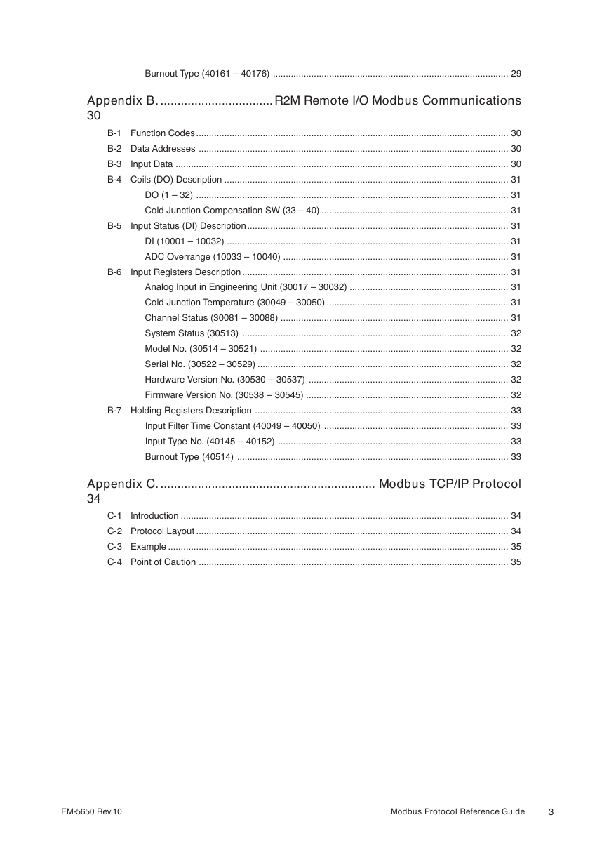
Burnout Type (40161 – 40176) ............................................................................................ 29 Appendix B. ................................. R2M Remote I/O Modbus Communications 30 B-1 Function Codes .......................................................................................................................... 30 B-2 Data Addresses ......................................................................................................................... 30 B-3 Input Data .................................................................................................................................. 30 B-4 Coils (DO) Description ............................................................................................................... 31 DO (1 – 32) .......................................................................................................................... 31 Cold Junction Compensation SW (33 – 40) ......................................................................... 31 B-5 Input Status (DI) Description ...................................................................................................... 31 DI (10001 – 10032) .............................................................................................................. 31 ADC Overrange (10033 – 10040) ........................................................................................ 31 B-6 Input Registers Description ........................................................................................................ 31 Analog Input in Engineering Unit (30017 – 30032) .............................................................. 31 Cold Junction Temperature (30049 – 30050) ....................................................................... 31 Channel Status (30081 – 30088) ......................................................................................... 31 System Status (30513) ........................................................................................................ 32 Model No. (30514 – 30521) ................................................................................................. 32 Serial No. (30522 – 30529) .................................................................................................. 32 Hardware Version No. (30530 – 30537) .............................................................................. 32 Firmware Version No. (30538 – 30545) ............................................................................... 32 B-7 Holding Registers Description ................................................................................................... 33 Input Filter Time Constant (40049 – 40050) ........................................................................ 33 Input Type No. (40145 – 40152) .......................................................................................... 33 Burnout Type (40514) .......................................................................................................... 33 Appendix C. ............................................................... Modbus TCP/IP Protocol 34 C-1 Introduction ................................................................................................................................ 34 C-2 Protocol Layout .......................................................................................................................... 34 C-3 Example ..................................................................................................................................... 35 C-4 Point of Caution ......................................................................................................................... 35 EM-5650 Rev.10 Modbus Protocol Reference Guide 3
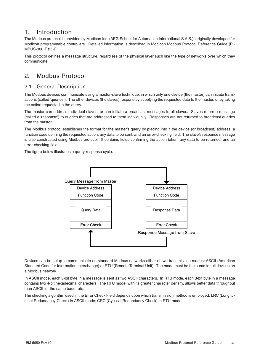
Introduction 1. The Modbus protocol is provided by Modicon Inc. (AEG Schneider Automation International S.A.S.), originally developed for Modicon programmable controllers. Detailed information is described in Modicon Modbus Protocol Reference Guide (PI- MBUS-300 Rev. J). This protocol defines a message structure, regardless of the physical layer such like the type of networks over which they communicate. 2. Modbus Protocol 2.1 General Description The Modbus devices communicate using a master-slave technique, in which only one device (the master) can initiate trans- actions (called ‘queries’). The other devices (the slaves) respond by supplying the requested data to the master, or by taking the action requested in the query. The master can address individual slaves, or can initiate a broadcast messages to all slaves. Slaves return a message (called a ‘response’) to queries that are addressed to them individually. Responses are not returned to broadcast queries from the master. The Modbus protocol establishes the format for the master’s query by placing into it the device (or broadcast) address, a function code defining the requested action, any data to be sent, and an error-checking field. The slave’s response message is also constructed using Modbus protocol. It contains fields confirming the action taken, any data to be returned, and an error-checking field. The figure below illustrates a query-response cycle. Query Message from Master Device Address Function Code Query Data Error Check Device Address Function Code Response Data Error Check Response Message from Slave Devices can be setup to communicate on standard Modbus networks either of two transmission modes: ASCII (American Standard Code for Information Interchange) or RTU (Remote Terminal Unit). The mode must be the same for all devices on a Modbus network. In ASCII mode, each 8-bit byte in a message is sent as two ASCII characters. In RTU mode, each 8-bit byte in a message contains two 4-bit hexadecimal characters. The RTU mode, with its greater character density, allows better data throughput than ASCII for the same baud rate. The checking algorithm used in the Error Check Field depends upon which transmission method is employed; LRC (Longitu- dinal Redundancy Check) in ASCII mode; CRC (Cyclical Redundancy Check) in RTU mode. EM-5650 Rev.10 Modbus Protocol Reference Guide 4
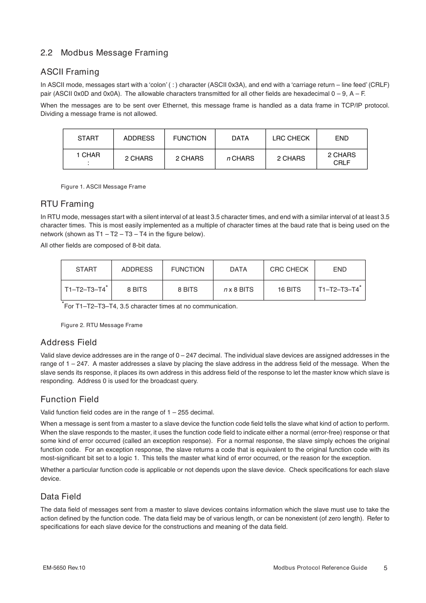
2.2 Modbus Message Framing ASCII Framing In ASCII mode, messages start with a ‘colon’ ( : ) character (ASCII 0x3A), and end with a ‘carriage return – line feed’ (CRLF) pair (ASCII 0x0D and 0x0A). The allowable characters transmitted for all other fields are hexadecimal 0 – 9, A – F. When the messages are to be sent over Ethernet, this message frame is handled as a data frame in TCP/IP protocol. Dividing a message frame is not allowed. START ADDRESS FUNCTION DATA LRC CHECK END 1 CHAR : 2 CHARS 2 CHARS n CHARS 2 CHARS 2 CHARS CRLF Figure 1. ASCII Message Frame RTU Framing In RTU mode, messages start with a silent interval of at least 3.5 character times, and end with a similar interval of at least 3.5 character times. This is most easily implemented as a multiple of character times at the baud rate that is being used on the network (shown as T1 – T2 – T3 – T4 in the figure below). All other fields are composed of 8-bit data. START ADDRESS FUNCTION DATA CRC CHECK END T1–T2–T3–T4* 8 BITS 8 BITS n x 8 BITS 16 BITS T1–T2–T3–T4* *For T1–T2–T3–T4, 3.5 character times at no communication. Figure 2. RTU Message Frame Address Field Valid slave device addresses are in the range of 0 – 247 decimal. The individual slave devices are assigned addresses in the range of 1 – 247. A master addresses a slave by placing the slave address in the address field of the message. When the slave sends its response, it places its own address in this address field of the response to let the master know which slave is responding. Address 0 is used for the broadcast query. Function Field Valid function field codes are in the range of 1 – 255 decimal. When a message is sent from a master to a slave device the function code field tells the slave what kind of action to perform. When the slave responds to the master, it uses the function code field to indicate either a normal (error-free) response or that some kind of error occurred (called an exception response). For a normal response, the slave simply echoes the original function code. For an exception response, the slave returns a code that is equivalent to the original function code with its most-significant bit set to a logic 1. This tells the master what kind of error occurred, or the reason for the exception. Whether a particular function code is applicable or not depends upon the slave device. Check specifications for each slave device. Data Field The data field of messages sent from a master to slave devices contains information which the slave must use to take the action defined by the function code. The data field may be of various length, or can be nonexistent (of zero length). Refer to specifications for each slave device for the constructions and meaning of the data field. EM-5650 Rev.10 Modbus Protocol Reference Guide 5
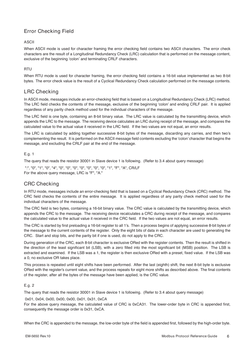
Error Checking Field ASCII When ASCII mode is used for character framing the error checking field contains two ASCII characters. The error check characters are the result of a Longitudinal Redundancy Check (LRC) calculation that is performed on the message content, exclusive of the beginning ‘colon’ and terminating CRLF characters. RTU When RTU mode is used for character framing, the error checking field contains a 16-bit value implemented as two 8-bit bytes. The error check value is the result of a Cyclical Redundancy Check calculation performed on the message contents. LRC Checking In ASCII mode, messages include an error-checking field that is based on a Longitudinal Redundancy Check (LRC) method. The LRC field checks the contents of the message, exclusive of the beginning ‘colon’ and ending CRLF pair. It is applied regardless of any parity check method used for the individual characters of the message. The LRC field is one byte, containing an 8-bit binary value. The LRC value is calculated by the transmitting device, which appends the LRC to the message. The receiving device calculates an LRC during receipt of the message, and compares the calculated value to the actual value it received in the LRC field. If the two values are not equal, an error results. The LRC is calculated by adding together successive 8-bit bytes of the message, discarding any carries, and then two’s complementing the result. It is performed on the ASCII message field contents excluding the ‘colon’ character that begins the message, and excluding the CRLF pair at the end of the message. E.g. 1 The query that reads the resistor 30001 in Slave device 1 is following. (Refer to 3.4 about query message) ":", "0", "1", "0", "4", "0", "0", "0", "0", "0", "0", "0", "1", "F", "A", CR/LF For the above query message, LRC is "F", "A." CRC Checking In RTU mode, messages include an error-checking field that is based on a Cyclical Redundancy Check (CRC) method. The CRC field checks the contents of the entire message. It is applied regardless of any parity check method used for the individual characters of the message. The CRC field is two bytes, containing a 16-bit binary value. The CRC value is calculated by the transmitting device, which appends the CRC to the message. The receiving device recalculates a CRC during receipt of the message, and compares the calculated value to the actual value it received in the CRC field. If the two values are not equal, an error results. The CRC is started by first preloading a 16-bit register to all 1’s. Then a process begins of applying successive 8-bit bytes of the message to the current contents of the register. Only the eight bits of data in each character are used to generating the CRC. Start and stop bits, and the parity bit if one is used, do not apply to the CRC. During generation of the CRC, each 8-bit character is exclusive ORed with the register contents. Then the result is shifted in the direction of the least significant bit (LSB), with a zero filled into the most significant bit (MSB) position. The LSB is extracted and examined. If the LSB was a 1, the register is then exclusive ORed with a preset, fixed value. If the LSB was a 0, no exclusive OR takes place. This process is repeated until eight shifts have been performed. After the last (eighth) shift, the next 8-bit byte is exclusive ORed with the register’s current value, and the process repeats for eight more shifts as described above. The final contents of the register, after all the bytes of the message have been applied, is the CRC value. E.g. 2 The query that reads the resistor 30001 in Slave device 1 is following. (Refer to 3.4 about query message) 0x01, 0x04, 0x00, 0x00, 0x00, 0x01, 0x31, 0xCA For the above query message, the calculated value of CRC is 0xCA31. The lower-order byte in CRC is appended first, consequently the message order is 0x31, 0xCA. When the CRC is appended to the message, the low-order byte of the field is appended first, followed by the high-order byte. EM-5650 Rev.10 Modbus Protocol Reference Guide 6
2.3 Modbus Function Formats Data Address Data addresses are used in Modbus query messages when reading or modifying data. Four types of data are used: Coil, Input Status, Input Register and Holding Register. Coil Coils are used to force the ON/OFF state of discrete outputs (DO) to the field, or to modify the mode or status of slave devices. Coil data is either ON or OFF, which can be both read and modified. Valid addresses are in the range of 1 – 9999. Input Status Input Status is used for the ON/OFF state of discrete inputs (DI) from the field, or the status of slave devices. The input status is either ON or OFF, which can be read only. Valid addresses are in the range of 10001 – 19999. Input Register Input registers are used for the value of analog inputs (AI) from the field, or the information of slave devices. The input register is of 16-bit long, which can be read only. Valid addresses are in the range of 30001 – 39999. Floating or double- floating data can be handled when consecutive addresses are assigned. Holding Register Holding registers are used for the value of analog outputs (AO) to the field, or to set information of slave devices. The holding register is of 16-bit long, which can be both read and modified. Valid addresses are in the range of 40001 – 49999. Floating or double-floating data can be handled when consecutive addresses are assigned. EM-5650 Rev.10 Modbus Protocol Reference Guide 7
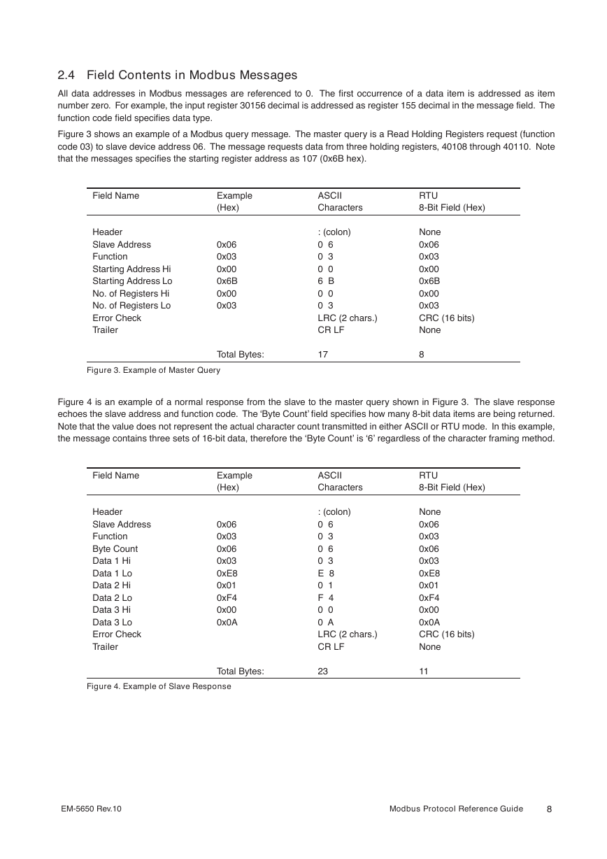
2.4 Field Contents in Modbus Messages All data addresses in Modbus messages are referenced to 0. The first occurrence of a data item is addressed as item number zero. For example, the input register 30156 decimal is addressed as register 155 decimal in the message field. The function code field specifies data type. Figure 3 shows an example of a Modbus query message. The master query is a Read Holding Registers request (function code 03) to slave device address 06. The message requests data from three holding registers, 40108 through 40110. Note that the messages specifies the starting register address as 107 (0x6B hex). Field Name Header Slave Address Function Starting Address Hi Starting Address Lo No. of Registers Hi No. of Registers Lo Error Check Trailer Example (Hex) 0x06 0x03 0x00 0x6B 0x00 0x03 ASCII Characters : (colon) 0 6 0 3 0 0 6 B 0 0 0 3 LRC (2 chars.) CR LF RTU 8-Bit Field (Hex) None 0x06 0x03 0x00 0x6B 0x00 0x03 CRC (16 bits) None Figure 3. Example of Master Query Total Bytes: 17 8 Figure 4 is an example of a normal response from the slave to the master query shown in Figure 3. The slave response echoes the slave address and function code. The ‘Byte Count’ field specifies how many 8-bit data items are being returned. Note that the value does not represent the actual character count transmitted in either ASCII or RTU mode. In this example, the message contains three sets of 16-bit data, therefore the ‘Byte Count’ is ‘6’ regardless of the character framing method. Field Name Header Slave Address Function Byte Count Data 1 Hi Data 1 Lo Data 2 Hi Data 2 Lo Data 3 Hi Data 3 Lo Error Check Trailer Example (Hex) 0x06 0x03 0x06 0x03 0xE8 0x01 0xF4 0x00 0x0A ASCII Characters : (colon) 0 6 0 3 0 6 0 3 E 8 0 1 F 4 0 0 0 A LRC (2 chars.) CR LF RTU 8-Bit Field (Hex) None 0x06 0x03 0x06 0x03 0xE8 0x01 0xF4 0x00 0x0A CRC (16 bits) None Figure 4. Example of Slave Response Total Bytes: 23 11 EM-5650 Rev.10 Modbus Protocol Reference Guide 8
分享到:
收藏