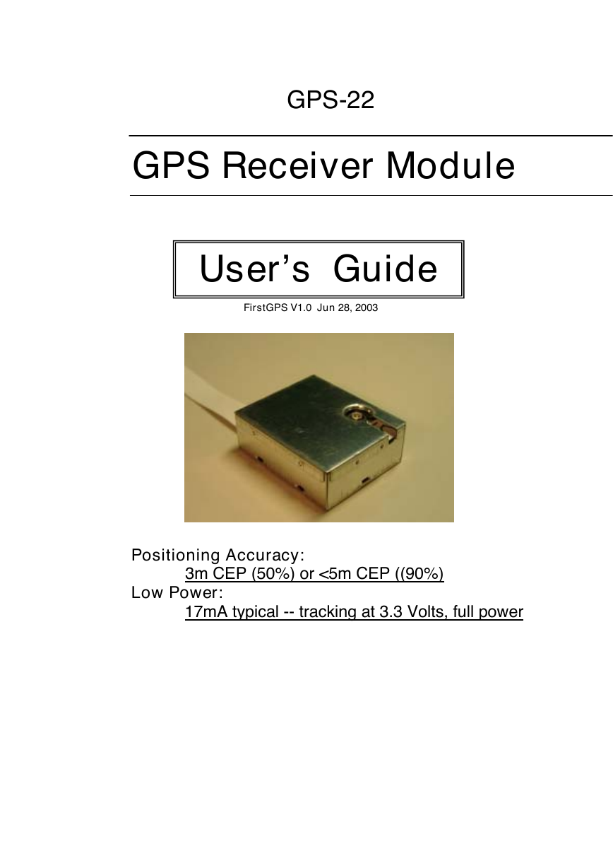
GPS-22
GPS Receiver Module
User’s Guide
FirstGPS V1.0 Jun 28, 2003
Positioning Accuracy:
3m CEP (50%) or <5m CEP ((90%)
Low Power:
17mA typical -- tracking at 3.3 Volts, full power
�
GPS-22 Operating Manual
TABLE OF CONTENTS
1. Introduction ………………………………………………………………………….………… 3
3
1.1 Overview ……………………………………………………………………………………….
1.2 Features ……………………………………………………………………………….………. 3
1.3 FirstGPS Architecture Highlights …………………………………………………………… 3
1.4 Application …………………………………………………………………………………….. 3
1.3 Technology specifications ………………………………………………………………….… 3
5
2. Operational Characteristic ……………………………………………………………….
5
2.1 Initialization ……………………………………………………………………………………
2.2 Navigation …………………………………………………………………………………….. 5
3. Hardware Interface …….……………………………………………………………………. 6
6
3.1 Physical Characters …………………………………………………………………………
6
3.2 Pin Definition …………………………………………………………………………………
4. Software Interface ……………..…………………………………………………….……….
8
4.1 NMEA Transmitted Message ……………………………………………………….………. 8
4.2 RTCM Received Data ………………..…………………………………………………….. 11
4.3 Syntax Setting ………………………………………………………………………………… 11
4.4 Default Setting Details ………………………………………………………………………… 14
4.5 Application Information ……………………………………………………………………… 15
5. Earth Datums ………………………………………………………………………………….. 16
5.1 Earth Datums ………………………………………………………………………………… 16
6. Ordering Information ………………………………………………………………………. 16
6.1 Products Options ……………………………………………………………………..……… 16
6.2 Accessories ……………………………………………………………………..…………….. 16
7. Warranty …………………………………………………………………………..…………….. 16
Specifications subject to change without prior notice
2
�
GPS-22 Operating Manual
1. Introduction
1.1 Overview
The GPS-22 GPS Receiver is a GPS receiver featuring the revolutionary FirstGPS™ architecture. This
complete enabled GPS receiver module provides high position and speed accuracy performances as well
as high sensitivity and tracking capabilities in urban canyon conditions. The solution enables small form
factor package. The GPS-22 delivers major advancements in GPS performances, accuracy, integration,
computing power and flexibility. It is designed to simplify the embedded system integration process.
This positioning application meets strict needs such as car navigation, mapping, surveying, agriculture and
so on. Only clear view of sky and certain power supply are necessary to the unit. GPS-22 communicates
with other electronic utilities via compatible dual-channel through TTL and saves critical satellite data in
built–in memory backup. With low power consumption, the GPS-22 tracks up to 8 satellites at a time,
re-acquires satellite signals in 100 ms and updates position data every second.
1.2 Features
The GPS-22 provides a host of features that make it easy for integration and use.
1. Position accuracy in < 3m CEP (50%) or <5m CEP ((90%) without SA (horizontal)
2. Ultra low power: 17mA typical -- tracking at 3.3 Volts, full power
3. High sensitivity: to -143 dBm tracking, superior urban canyon performances
4. Small form factor and low cost solution
5. Ready-to-plug solution. Easily integrated into existing systems
6. On-board RAM for GPS navigation data
7. PPS output (User may have different interval setting from 1 second to 1 minute.
8. Differential capability utilizes real-time RTCM corrections producing < 1 meter position accuracy.
9. FLASH based program memory: New setting is stored permanently.
1.3 FirstGPS Architecture Highlights
1.3.1 Industry Leading GPS Performance
core
- Builds on high performance FirstGPSTM
- Satellite signal tracking engine to perform GPS acquisition and tracking functions without CPU
intervention
- High sensitivity: to -143 dBm tracking, superior urban canyon performances
- Position accuracy: < 3m CEP (50%) without SA (horizontal)
- Warm Start is under 42 seconds (90%)
- Hot Start is under 10 seconds (90%)
1.3.2 Low Power
- Ultra low power integrated circuit design, optimized RF and DSP architectures
- Further power saving thanks to 4 different power down mode
1.4 Application
1. Car Navigation
2. Mapping
3. Surveying
4. Agriculture
5. Palmtop, Laptop, PDA
6. Location Based Services enabled devices
7. Asset management/tracking
8. Handheld receivers
1.5 Technology specifications
1.5.1 Physical Dimension
1. Size: 31.59(W) x 26.59(D) x 11.20(H) (mm)
1.24”(W) x 1.05”(D) x 0.44”(H)
2. Weight: 25 g
Remark: FirstGPS™ is the trademark from Trimble
Specifications subject to change without prior notice
3
�
GPS-22 Operating Manual
ANT
ANT
Input voltage: +3.0 ~ 3.65 VDC.
1.5.2 Environmental Characteristics
1) Operating temperature: -40oC to +85oC (internal temperature)
2) Storage temperature: -55oC to +100oC
1.5.3 Electrical Characteristics
1)
2) HFL antenna connector: Active or patch (3.0V antenna is recommended).
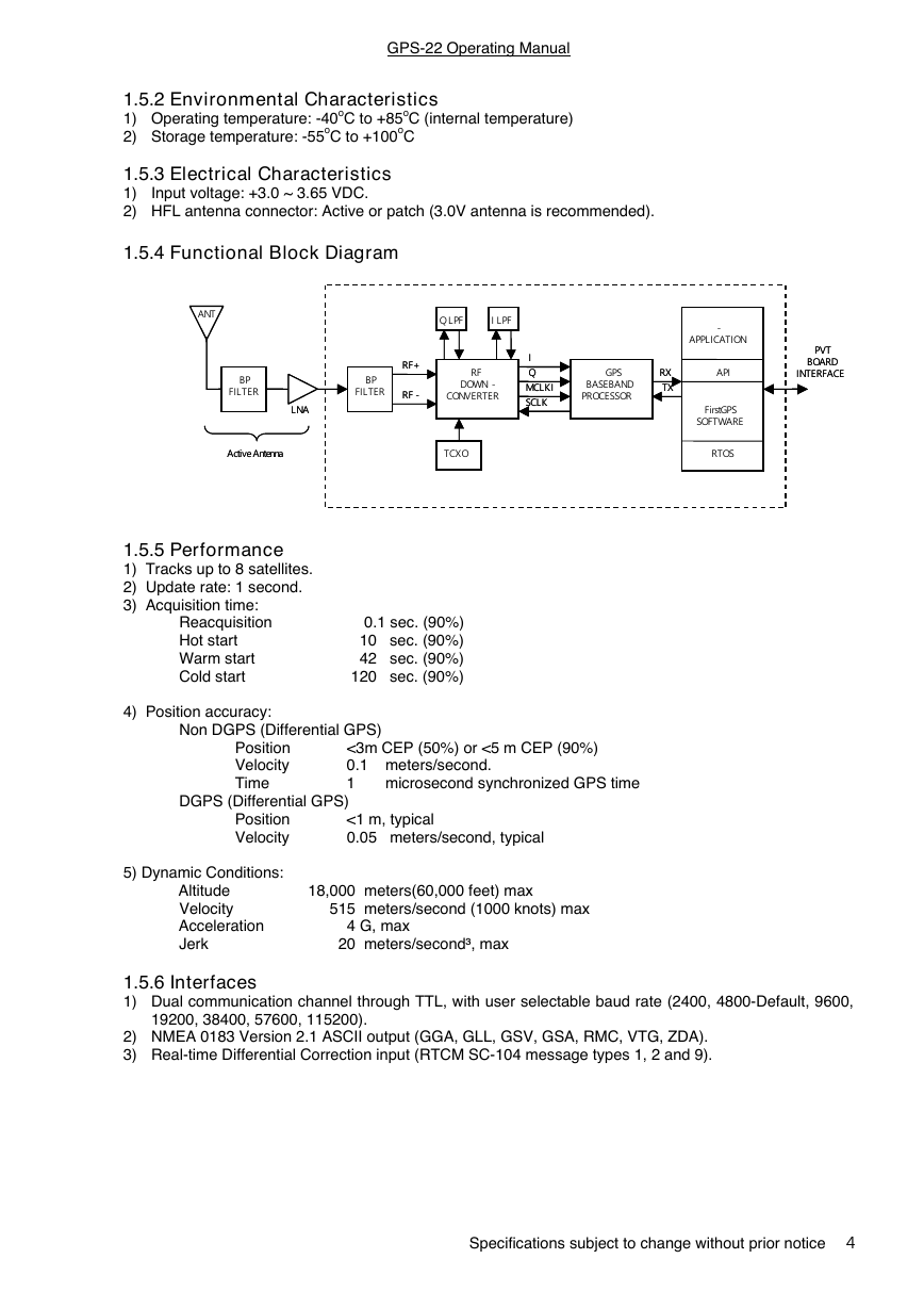
1.5.4 Functional Block Diagram
1.5.5 Performance
1) Tracks up to 8 satellites.
2) Update rate: 1 second.
3) Acquisition time:
DOWN -
DOWN -
CONVERTER
CONVERTER
BASEBAND
BASEBAND
PROCESSOR
PROCESSOR
BP
BP
FILTER
FILTER
BP
BP
FILTER
FILTER
MCLKI
MCLKI
SCLK
SCLK
Q LPF
Q LPF
I LPF
I LPF
RF+
RF+
RF -
RF -
RF
RF
GPS
GPS
Active Antenna
Active Antenna
TCXO
TCXO
LNA
LNA
I
I
Q
Q
Reacquisition
Hot start
Warm start
Cold start
4) Position accuracy:
0.1 sec. (90%)
10 sec. (90%)
42 sec. (90%)
120 sec. (90%)
PVT
PVT
BOARD
BOARD
INTERFACE
INTERFACE
XE1610 - OEMPVT
APPLICATION
APPLICATION
-
RX
RX
TX
TX
API
API
FirstGPS
FirstGPS
SOFTWARE
SOFTWARE
RTOS
RTOS
Non DGPS (Differential GPS)
Position
Velocity
Time
DGPS (Differential GPS)
<3m CEP (50%) or <5 m CEP (90%)
0.1 meters/second.
1 microsecond synchronized GPS time
Position
Velocity
<1 m, typical
0.05 meters/second, typical
5) Dynamic Conditions:
Altitude
Velocity
Acceleration
Jerk
18,000 meters(60,000 feet) max
515 meters/second (1000 knots) max
4 G, max
20 meters/second³, max
1.5.6 Interfaces
1) Dual communication channel through TTL, with user selectable baud rate (2400, 4800-Default, 9600,
19200, 38400, 57600, 115200).
2) NMEA 0183 Version 2.1 ASCII output (GGA, GLL, GSV, GSA, RMC, VTG, ZDA).
3) Real-time Differential Correction input (RTCM SC-104 message types 1, 2 and 9).
Specifications subject to change without prior notice
4
�
GPS-22 Operating Manual
2. Operational characteristics
2.1 Initialization
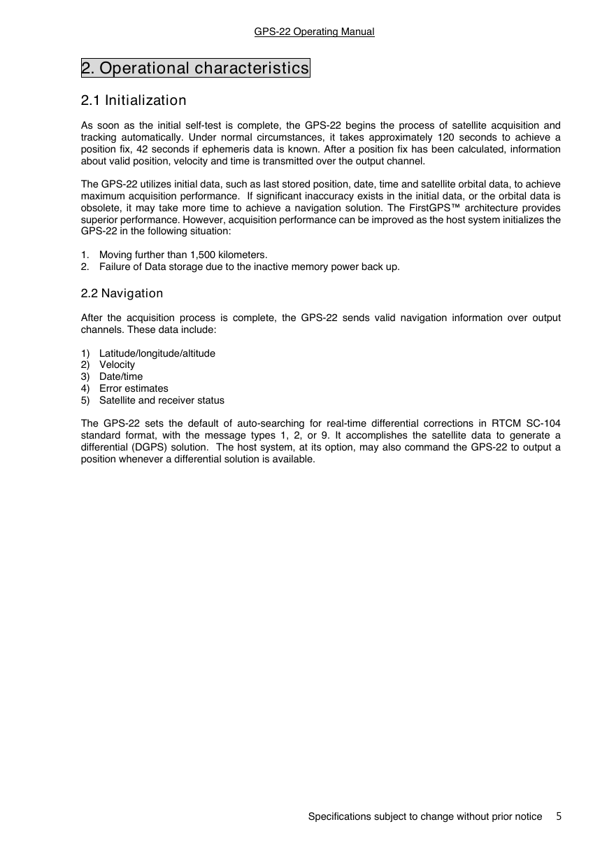
As soon as the initial self-test is complete, the GPS-22 begins the process of satellite acquisition and
tracking automatically. Under normal circumstances, it takes approximately 120 seconds to achieve a
position fix, 42 seconds if ephemeris data is known. After a position fix has been calculated, information
about valid position, velocity and time is transmitted over the output channel.
The GPS-22 utilizes initial data, such as last stored position, date, time and satellite orbital data, to achieve
maximum acquisition performance. If significant inaccuracy exists in the initial data, or the orbital data is
obsolete, it may take more time to achieve a navigation solution. The FirstGPS™ architecture provides
superior performance. However, acquisition performance can be improved as the host system initializes the
GPS-22 in the following situation:
1. Moving further than 1,500 kilometers.
2. Failure of Data storage due to the inactive memory power back up.
2.2 Navigation
After the acquisition process is complete, the GPS-22 sends valid navigation information over output
channels. These data include:
1) Latitude/longitude/altitude
2) Velocity
3) Date/time
4) Error estimates
5) Satellite and receiver status
The GPS-22 sets the default of auto-searching for real-time differential corrections in RTCM SC-104
standard format, with the message types 1, 2, or 9. It accomplishes the satellite data to generate a
differential (DGPS) solution. The host system, at its option, may also command the GPS-22 to output a
position whenever a differential solution is available.
Specifications subject to change without prior notice
5
�
GPS-22 Operating Manual
3. Hardware interface
3.1 Physical Characters
1. Size: 31.59(W) x 26.59(D) x 11.20(H) (mm)
1.24”(W) x 1.05”(D) x 0.44”(H)
2. Weight: 25 g
3.1.1 Details Drawing
3.2 Pin Definition
PIN
1
2
3
4
5
6
7
8
9
10
11
12
NAME
GND
ON/OFF
VCC
USPED
RXA
VRTCBK
TXA
PPS
GND
RESETN
ALMRDY
STY1
TYPE
I
I
I
O
O
I
STY0
OSCSTOPN
DESCRIPTION
Power and Signal Ground
ON / Off command line
3.0 to 3.6 Volts DC Input Power Supply
9600/4800 Bd UART Speed
Serial Receive Data, Port A, GPS NMEA Data
Back-up supply for the RTC
Serial Transmit Data, Port A, GPS NMEA Data
One Pulse Per Second timing output
Power and Signal Ground
Manual Reset, Active low
1(high): almanac valid; 0 (low): almanac not valid
Blinking function, when position fix, output “low”. When
tracking, output the interval signal “high/low”.
N.C.
For customer specific version
N.C.
Stand-by active “low”
13
14
15
16
1) All I/Os on the Data Interface are related to VCC (3 to 3.6 Volts) and GND levels.
Specifications subject to change without prior notice
6
�
GPS-22 Operating Manual
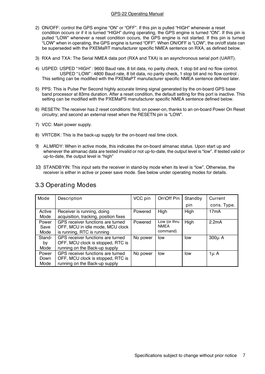
2) ON/OFF: control the GPS engine “ON” or “OFF”. If this pin is pulled “HIGH” whenever a reset
condition occurs or if it is turned “HIGH” during operating, the GPS engine is turned “ON”. If this pin is
pulled “LOW” whenever a reset condition occurs, the GPS engine is not started. If this pin is turned
“LOW” when in operating, the GPS engine is turned “OFF”. When ON/OFF is “LOW”, the on/off state can
be superseded with the PXEMaRT manufacturer specific NMEA sentence on RXA, as defined below.
3) RXA and TXA: The Serial NMEA data port (RXA and TXA) is an asynchronous serial port (UART).
4) USPED: USPED “HIGH”: 9600 Baud rate, 8 bit data, no parity check, 1 stop bit and no flow control.
USPED “LOW”: 4800 Baud rate, 8 bit data, no parity check, 1 stop bit and no flow control .
This setting can be modified with the PXEMaPT manufacturer specific NMEA sentence defined later.
5) PPS: This is Pulse Per Second highly accurate timing signal generated by the on-board GPS base
band processor at 83ms duration. After a reset condition, the default setting for this port is inactive. This
setting can be modified with the PXEMaPS manufacturer specific NMEA sentence defined below.
6) RESETN: The receiver has 2 reset conditions: first, on power-on, thanks to an on-board Power On Reset
circuitry; and second an external reset when the RESETN pin is “LOW”.
7) VCC: Main power supply.
8) VRTCBK: This is the back-up supply for the on-board real time clock.
9) ALMRDY: When in active mode, this indicates the on-board almanac status. Upon start up and
whenever the almanac data are tested invalid or not up-to-date, the output level is “low”. If tested valid or
up-to-date, the output level is “high”
10) STANDBYIN: This input sets the receiver in stand-by mode when its level is “low”. Otherwise, the
receiver is either in active or power save mode. See below under operating modes for details.
3.3 Operating Modes
Mode
Description
VCC pin On\Off Pin Standby
Receiver is running, doing
acquisition, tracking, position fixes
GPS receiver functions are turned
OFF, MCU in idle mode, MCU clock
is running, RTC is running
GPS receiver functions are turned
OFF, MCU clock is stopped, RTC is
running on the Back-up supply
GPS receiver functions are turned
OFF, MCU clock is stopped, RTC is
running on the Back-up supply
Powered High
Powered
No power
Low (or thru
NMEA
command)
low
No power
low
pin
High
High
low
low
Active
Mode
Power
Save
Mode
Stand-
by
Mode
Power
Down
Mode
Current
cons. Type.
17mA
2.2mA
300gA
1gA
Specifications subject to change without prior notice
7
�
GPS-22 Operating Manual
4. Software Interface
The GPS-22 interface protocol is based on the National Marine Electronics Association's NMEA 0183 ASC
Ⅱinterface specification, which is defined in NMEA 0183, Version 2.1 and the Radio Technical Commission
for Maritime Services (RTCM Recommended Standards For Differential Navstar GPS Service, Version 2.1,
RTCM Special Committee No.104).
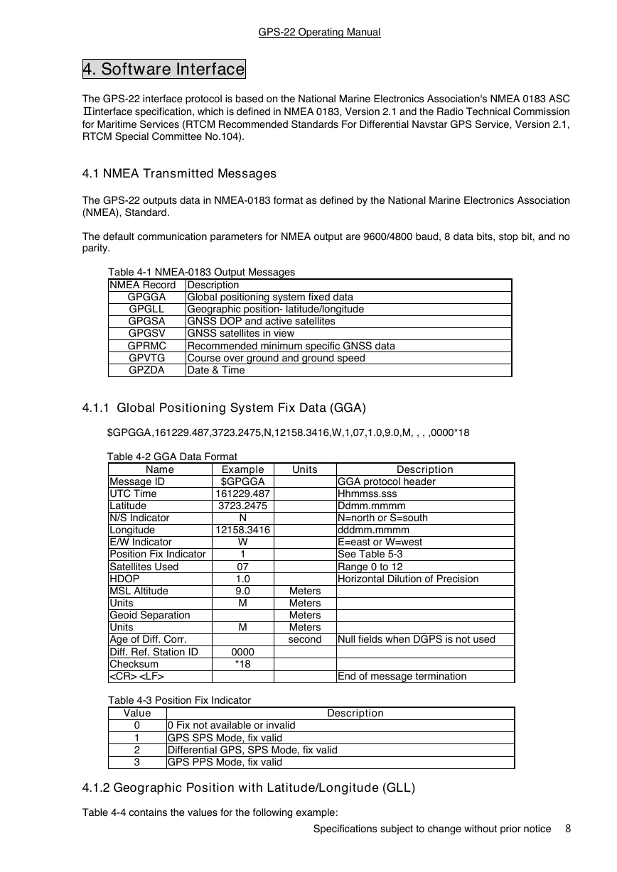
4.1 NMEA Transmitted Messages
The GPS-22 outputs data in NMEA-0183 format as defined by the National Marine Electronics Association
(NMEA), Standard.
The default communication parameters for NMEA output are 9600/4800 baud, 8 data bits, stop bit, and no
parity.
Table 4-1 NMEA-0183 Output Messages
NMEA Record Description
GPGGA
GPGLL
GPGSA
GPGSV
GPRMC
GPVTG
GPZDA
Global positioning system fixed data
Geographic position- latitude/longitude
GNSS DOP and active satellites
GNSS satellites in view
Recommended minimum specific GNSS data
Course over ground and ground speed
Date & Time
4.1.1 Global Positioning System Fix Data (GGA)
$GPGGA,161229.487,3723.2475,N,12158.3416,W,1,07,1.0,9.0,M, , , ,0000*18
Table 4-2 GGA Data Format
Name
Message ID
UTC Time
Latitude
N/S Indicator
Longitude
E/W Indicator
Position Fix Indicator
Satellites Used
HDOP
MSL Altitude
Units
Geoid Separation
Units
Age of Diff. Corr.
Diff. Ref. Station ID
Checksum
Example
$GPGGA
161229.487
3723.2475
12158.3416
N
W
1
07
1.0
9.0
M
M
0000
*18
Table 4-3 Position Fix Indicator
Units
Description
GGA protocol header
Hhmmss.sss
Ddmm.mmmm
N=north or S=south
dddmm.mmmm
E=east or W=west
See Table 5-3
Range 0 to 12
Horizontal Dilution of Precision
Meters
Meters
Meters
Meters
second Null fields when DGPS is not used
End of message termination
Value
0
1
2
3
0 Fix not available or invalid
GPS SPS Mode, fix valid
Differential GPS, SPS Mode, fix valid
GPS PPS Mode, fix valid
Description
4.1.2 Geographic Position with Latitude/Longitude (GLL)
Table 4-4 contains the values for the following example:
Specifications subject to change without prior notice
8
�




 2023年江西萍乡中考道德与法治真题及答案.doc
 2012年重庆南川中考生物真题及答案.doc
 2013年江西师范大学地理学综合及文艺理论基础考研真题.doc
 2020年四川甘孜小升初语文真题及答案I卷.doc
 2020年注册岩土工程师专业基础考试真题及答案.doc
 2023-2024学年福建省厦门市九年级上学期数学月考试题及答案.doc
 2021-2022学年辽宁省沈阳市大东区九年级上学期语文期末试题及答案.doc
 2022-2023学年北京东城区初三第一学期物理期末试卷及答案.doc
 2018上半年江西教师资格初中地理学科知识与教学能力真题及答案.doc
 2012年河北国家公务员申论考试真题及答案-省级.doc
 2020-2021学年江苏省扬州市江都区邵樊片九年级上学期数学第一次质量检测试题及答案.doc
 2022下半年黑龙江教师资格证中学综合素质真题及答案.doc