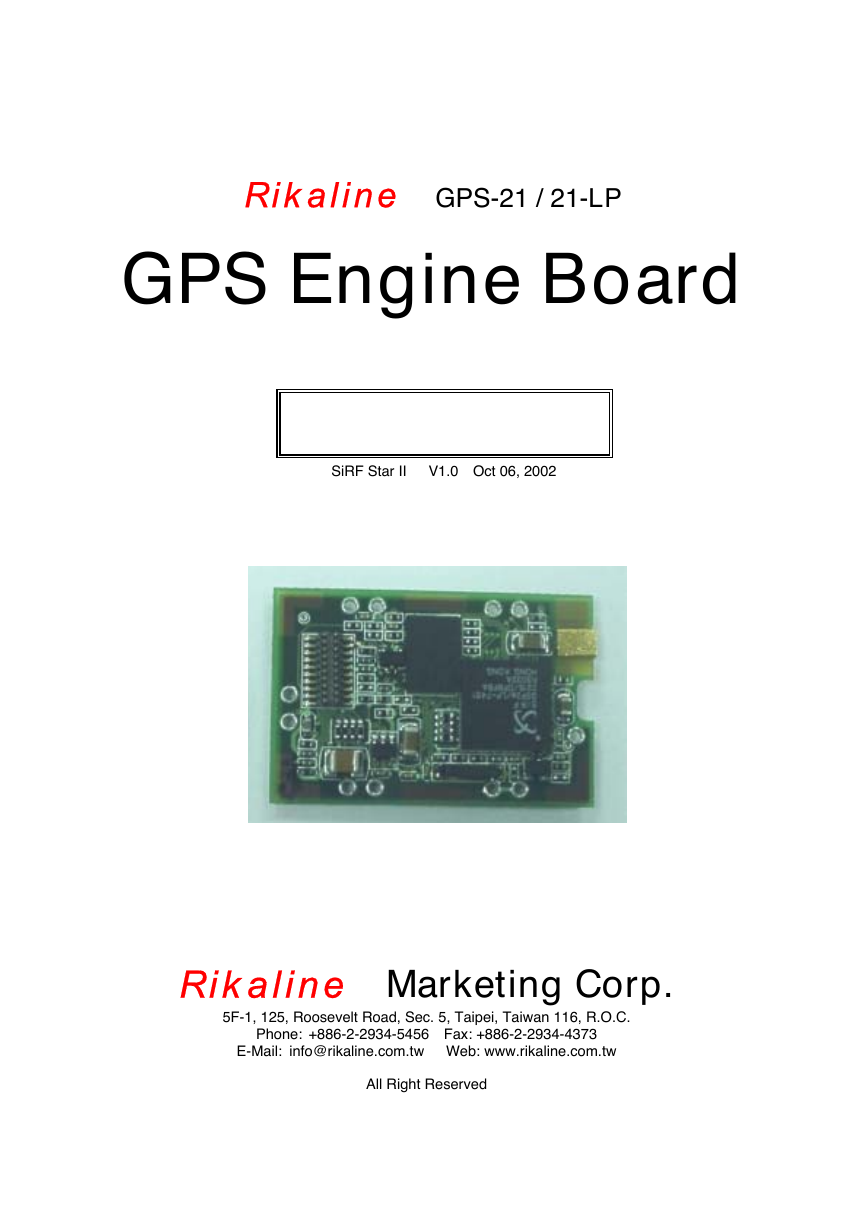
Rikaline GPS-21 / 21-LP
GPS Engine Board
User’s Guide
SiRF Star II V1.0 Oct 06, 2002
Rikaline Marketing Corp.
5F-1, 125, Roosevelt Road, Sec. 5, Taipei, Taiwan 116, R.O.C.
Phone: +886-2-2934-5456 Fax: +886-2-2934-4373
E-Mail: info@rikaline.com.tw Web: www.rikaline.com.tw
All Right Reserved
�
GPS-21 Operating Manual Rikaline
TABLE OF CONTENTS
3
3
3
3
1. Introduction ………………………………………………………………………………………..
1.1 Overview ……………………………………………………………………………………..
1.2 Features ……………………………………………………………………………………..
1.3 Technical Specifications ………………………………………………………………..
2. Operational Characteristics ……………………………………………………………….… 5
2.1 Initialization …………………………………………………………………………………. 5
2.2 Navigation …………………………………………………………………………………. 5
3. Hardware Interface ………………………………………………………………………….…… 6
3.1 Connector ………………………………………………………………………………….… 6
6
3.2 Pin Assignment …..………..……………………………………………………….……
3.3 Trickle Power …………………………………………………………………………….… 8
3.4 Push-to-Fix Description ………………………………………………………………… 9
3.5 SRAM Data Backup Description ……………………………………………………… 9
3.6 Mechanical Dimension …………………………………………………………………… 10
4. Software Interface …………………………………………………………………………….… 12
4.1 NMEA Transmitted Sentences ……………………………………………………..… 12
4.2 RTCM Received Data ………………………………………………………………….. 15
5. Earth Datums ………………………………………………………………………………………. 16
5.1 Earth Datums ……………………………………………………………………………….. 16
5.2 Setting Syntax …………………………………………………………………………….… 17
6. Ordering Information ………………………………………………………………………..… 18
6.1 Product Options ………………………………………………………………….………… 18
6.2 Accessories ………………………………………………………………………….……… 18
7. Warranty ……………………………………………………………………………………………… 18
Rikaline Marketing Corp.
Tel: ++886 2 2934 5456 Fax: ++886 2 2934 4373 E-Mail: info@rikaline.com.tw web: www.rikaline.com.tw
5F-1, 125, Roosevelt Road, Sec. 5, Taipei, Taiwan 116
2
�
GPS-21 Operating Manual Rikaline
1. Introduction
1.1 Overview
The Rikaline GPS-21 GPS Engine Board is designed based on SiRF Star II Architecture with low
power consumption, small size and easy integrated for a broad spectrum of OEM system applications.
GPS-21 meets strict needs such as car navigation, mapping, surveying, security, agriculture and so on. Only
clear view of sky and certain power supply are necessary to the unit. It communicates with other electronic
utilities via compatible dual-channel through RS-232 or TTL and saves critical satellite data by built–in
backup memory. The Trickle-Power allows the unit operates a fraction of the time and Push-to-Fix permits
user to have a quick position fix even though the receiver usually stays off.
The GPS-21-LP utilizes the latest SiRF technology for applications where the power consumption is more
critically required.
1.2 Features
The GPS-21 provides a host of features that make it easy for integration and use.
1. SiRF Star II chipset with embedded ARM7TDMI CPU available for customized applications in
2. High performance receiver tracks up to 12 satellites while providing first fast fix and low power
3. Differential capability utilizes real-time RTCM corrections producing 1-5 meter position accuracy.
4. Compact design ideal for applications with minimal space.
5. A rechargeable battery sustains internal clock and memory. The battery is recharged during normal
6. User initialization is not required.
7. Dual communication channels and user selectable baud rates allow maximum interface capability and
8. Optional communication levels, RS-232 and TTL meet ordinary application and new fashions of
connecting PDA with TTL or RS-232 output.
9. FLASH based program memory: New software revisions upgradeable through serial interface.
10. Built-in WAAS and EGNOS demodulator.
1.3 Technical specifications
1.3.1 Physical Characteristics
Dimension: 36(L) x 24(W) x 6(H) mm
1.42"(L) x 0.95"(W) x 0.24"(H).
firmware.
consumption.
operation.
flexibility.
Weight: 7g
1.3.2 Environmental Characteristics
1) Operating temperature: -40oC to +85oC
2) Storage temperature: -55oC to +100oC.
-45oC to +80oC with battery
1.3.3 Electrical Characteristics
1.3.3.1 General:
1) Frequency: L1, 1,575.42MHz
2) C/A Code: 1.023MHz Chip Rate
3) Channels: 12
Rikaline Marketing Corp.
Tel: ++886 2 2934 5456 Fax: ++886 2 2934 4373 E-Mail: info@rikaline.com.tw web: www.rikaline.com.tw
5F-1, 125, Roosevelt Road, Sec. 5, Taipei, Taiwan 116
3
�
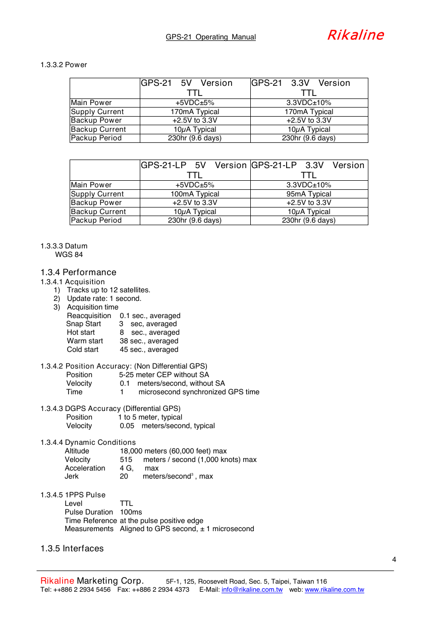
1.3.3.2 Power
Main Power
Supply Current
Backup Power
Backup Current
Packup Period
Main Power
Supply Current
Backup Power
Backup Current
Packup Period
1.3.3.3 Datum
WGS 84
1.3.4 Performance
1.3.4.1 Acquisition
1) Tracks up to 12 satellites.
2) Update rate: 1 second.
3) Acquisition time
Hot start
Warm start
Cold start
Reacquisition 0.1 sec., averaged
Snap Start 3 sec, averaged
8 sec., averaged
38 sec., averaged
45 sec., averaged
1.3.4.2 Position Accuracy: (Non Differential GPS)
Position 5-25 meter CEP without SA
Velocity
Time
1.3.4.3 DGPS Accuracy (Differential GPS)
Position 1 to 5 meter, typical
Velocity
0.05 meters/second, typical
1.3.4.4 Dynamic Conditions
0.1 meters/second, without SA
1 microsecond synchronized GPS time
1.3.4.5 1PPS Pulse
Altitude
Velocity
Acceleration
Jerk
18,000 meters (60,000 feet) max
515 meters / second (1,000 knots) max
4 G, max
20 meters/second3
, max
TTL
Level
Pulse Duration 100ms
Time Reference at the pulse positive edge
Measurements Aligned to GPS second, ± 1 microsecond
GPS-21 Operating Manual Rikaline
GPS-21 5V Version
GPS-21 3.3V Version
GPS-21-LP 5V Version
GPS-21-LP 3.3V Version
TTL
+5VDC±5%
170mA Typical
+2.5V to 3.3V
10µA Typical
230hr (9.6 days)
TTL
+5VDC±5%
100mA Typical
+2.5V to 3.3V
10µA Typical
230hr (9.6 days)
TTL
3.3VDC±10%
170mA Typical
+2.5V to 3.3V
10µA Typical
230hr (9.6 days)
TTL
3.3VDC±10%
95mA Typical
+2.5V to 3.3V
10µA Typical
230hr (9.6 days)
1.3.5 Interfaces
Rikaline Marketing Corp.
Tel: ++886 2 2934 5456 Fax: ++886 2 2934 4373 E-Mail: info@rikaline.com.tw web: www.rikaline.com.tw
5F-1, 125, Roosevelt Road, Sec. 5, Taipei, Taiwan 116
4
�
GPS-21 Operating Manual Rikaline
1.3.5.1 Interface
1.3.5.2 Protocol Message
1.3.5.2 DGPS Protocol
Two full duplex serial communication, RS-232 or TTL compatible level, with user selectable baud rate
(4800-Default, 9600, 19200, 38400).
SiRF Binary – Position, Velocity, Altitude, Status and Control
NMEA 0183 Version 2.2 ASCII output -- GGA, GLL, GSA, GSV, RMC, ZDA and VTG.
Real-time Differential Correction input (RTCM SC-104 version 2.00 message types 1, 5 and 9).
2. Operational characteristics
2.1 Initialization
As soon as the initial self-test is complete, the GPS-21 begins the process of satellite acquisition and
tracking automatically. Under normal circumstances, it takes approximately 45 seconds to achieve a position
fix, 38 seconds if ephemeris data is known. After a position fix has been calculated, information about valid
position, velocity and time is transmitted over the output channel.
The GPS-21 utilizes initial data, such as last stored position, date, time and satellite orbital data, to
achieve maximum acquisition performance. If significant inaccuracy exists in the initial data, or the orbital
data is obsolete, it may take more time to achieve a navigation solution. The GPS-21 Auto-locate feature is
capable of automatically determining a navigation solution without intervention from the host system.
However, acquisition performance can be improved when the host system initializes the GPS-21 in the
following situation:
1) Moving further than 500 kilometers.
2) Failure of data storage due to the inactive internal memory battery.
2.2 Navigation
After the acquisition process is complete, the GPS-21 sends valid navigation information over
output channels. These data include:
1) Latitude/longitude/altitude
2) Velocity
3) Date/time
4) Error estimates
5) Satellite and receiver status
The GPS-21 sets the default of auto-searching for real-time differential corrections in RTCM SC-104
standard format, with the message types 1, 5, or 9. It accomplishes the satellite data to generate a differential
(DGPS) solution. The host system, at its option, may also command the GPS-21 to output a position
whenever a differential solution is available.
Rikaline Marketing Corp.
Tel: ++886 2 2934 5456 Fax: ++886 2 2934 4373 E-Mail: info@rikaline.com.tw web: www.rikaline.com.tw
5F-1, 125, Roosevelt Road, Sec. 5, Taipei, Taiwan 116
5
�
GPS-21 Operating Manual Rikaline
3. Hardware interface
3.1 Connectors
3.1.1 Antenna Connector
MCX, RSMA
3.1.2 Interface Connector
20-Pin and 10-Pin straight header, 2mm pitch
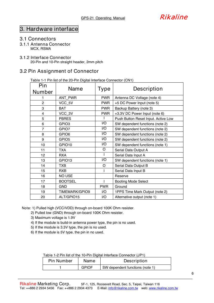
3.2 Pin Assignment of Connector
Table 1-1 Pin list of the 20-Pin Digital Interface Connector (CN1)
Pin
Number
Name
ANT_PWR
VCC_5V
BAT
VCC_3V
PBRES
GPIO3
GPIO7
GPIO6
GPIO5
GPIO10
TXA
RXA
GPIO13
TXB
RXB
NO USE
BOOTSEL
GND
TIMEMARK/GPIO9
ALT/GPIO15
Type
PWR
PWR
PWR
PWR
I
I/O
I/O
I/O
I/O
I/O
O
I
I/O
O
I
I
PWR
I/O
I/O
Description
Antenna DC Voltage (note 4)
+5 DC Power Input (note 5)
Backup Battery (note 3)
+3.3V DC Power Input (note 6)
Push Button Reset Input. Active Low
SW dependent functions (note 2)
SW dependent functions (note 2)
SW dependent functions (note 2)
SW dependent functions (note 2)
SW dependent functions (note 1)
Serial Data Output A
Serial Data Input A
SW dependent functions (note 1)
Serial Data Output B
Serial Data Input B
Reserve
Booting Mode Select
Ground
1PPS Time Mark Output (note 2)
Alternative output (note 1)
1
2
3
4
5
6
7
8
9
10
11
12
13
14
15
16
17
18
19
20
Note: 1) Pulled high (VCC/VDD) through on-board 100K Ohm resister.
2) Pulled low (GND) through on-board 100K Ohm resister.
3) Maximum voltage is 1.9V
4) If the module is build-in antenna power type, the pin is no used.
5) If the module is 3.3V type, the pin is no used.
6) If the module is 5V type, the pin in no used.
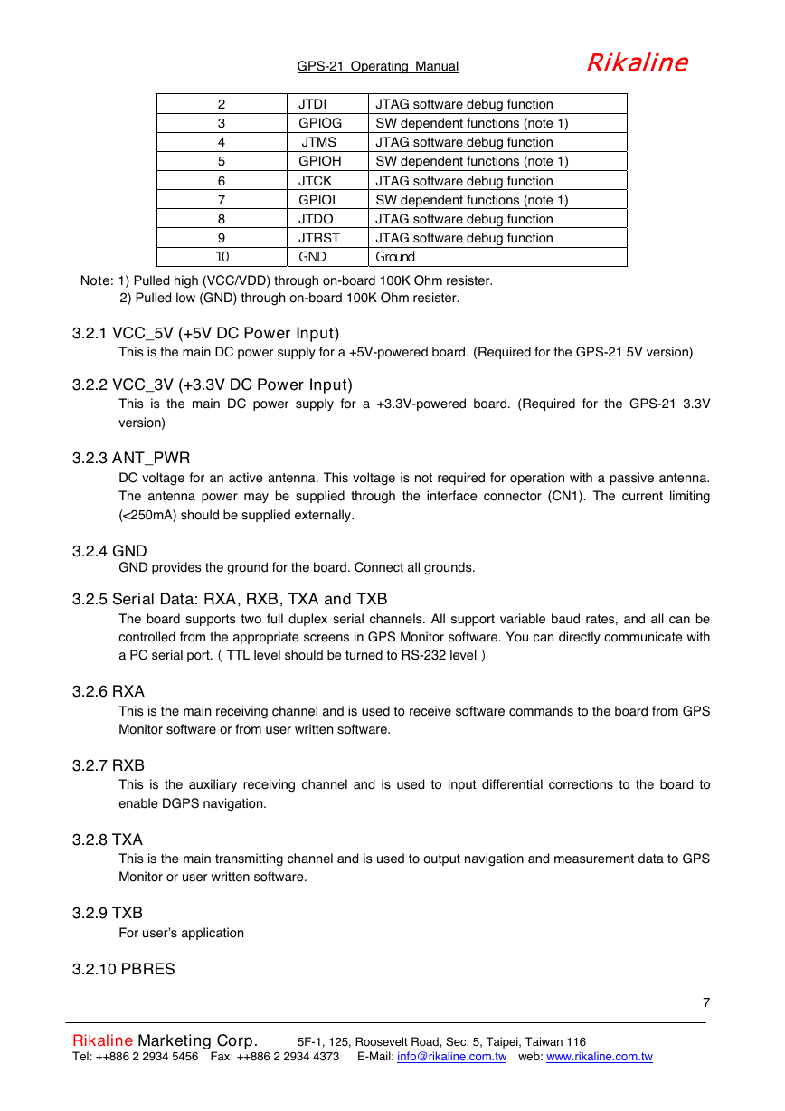
Table 1-2 Pin list of the 10-Pin Digital Interface Connector (JP1)
Description
Pin Number
1
SW dependent functions (note 1)
Name
GPIOF
Rikaline Marketing Corp.
Tel: ++886 2 2934 5456 Fax: ++886 2 2934 4373 E-Mail: info@rikaline.com.tw web: www.rikaline.com.tw
5F-1, 125, Roosevelt Road, Sec. 5, Taipei, Taiwan 116
6
�
GPS-21 Operating Manual Rikaline
2
3
4
5
6
7
8
9
10
JTDI
GPIOG
JTMS
GPIOH
JTCK
GPIOI
JTDO
JTRST
GND
JTAG software debug function
SW dependent functions (note 1)
JTAG software debug function
SW dependent functions (note 1)
JTAG software debug function
SW dependent functions (note 1)
JTAG software debug function
JTAG software debug function
Ground
Note: 1) Pulled high (VCC/VDD) through on-board 100K Ohm resister.
2) Pulled low (GND) through on-board 100K Ohm resister.
3.2.1 VCC_5V (+5V DC Power Input)
This is the main DC power supply for a +5V-powered board. (Required for the GPS-21 5V version)
3.2.2 VCC_3V (+3.3V DC Power Input)
This is the main DC power supply for a +3.3V-powered board. (Required for the GPS-21 3.3V
version)
3.2.3 ANT_PWR
DC voltage for an active antenna. This voltage is not required for operation with a passive antenna.
The antenna power may be supplied through the interface connector (CN1). The current limiting
(<250mA) should be supplied externally.
3.2.4 GND
GND provides the ground for the board. Connect all grounds.
3.2.5 Serial Data: RXA, RXB, TXA and TXB
The board supports two full duplex serial channels. All support variable baud rates, and all can be
controlled from the appropriate screens in GPS Monitor software. You can directly communicate with
a PC serial port.]TTL level should be turned to RS-232 level^
3.2.6 RXA
This is the main receiving channel and is used to receive software commands to the board from GPS
Monitor software or from user written software.
3.2.7 RXB
This is the auxiliary receiving channel and is used to input differential corrections to the board to
enable DGPS navigation.
3.2.8 TXA
This is the main transmitting channel and is used to output navigation and measurement data to GPS
Monitor or user written software.
3.2.9 TXB
For user’s application
3.2.10 PBRES
Rikaline Marketing Corp.
Tel: ++886 2 2934 5456 Fax: ++886 2 2934 4373 E-Mail: info@rikaline.com.tw web: www.rikaline.com.tw
5F-1, 125, Roosevelt Road, Sec. 5, Taipei, Taiwan 116
7
�
GPS-21 Operating Manual Rikaline
This pin provides an active-low reset input to the board. It causes the board to reset and start
searching for satellites. PB Reset is an optional input and, if not utilized, it may be left open.
3.2.11 Time mark
This pin provides 1 pulse per second output from the board, which is synchronized to within 1
microsecond of GPS time. The output is a TTL positive level signal.
This is not available in Trickle Power mode.
3.2.12 Battery (BAT)
This is the battery backup supply that powers the SRAM and RTC when main power is off. Typical
current draw is 10 µA.
Without an external backup battery or supercap, the board will execute a cold start after every turn
on. To achieve the faster start-up offered by a hot start or warm start, either a battery backup input
must be connected or a recharge battery installed
.
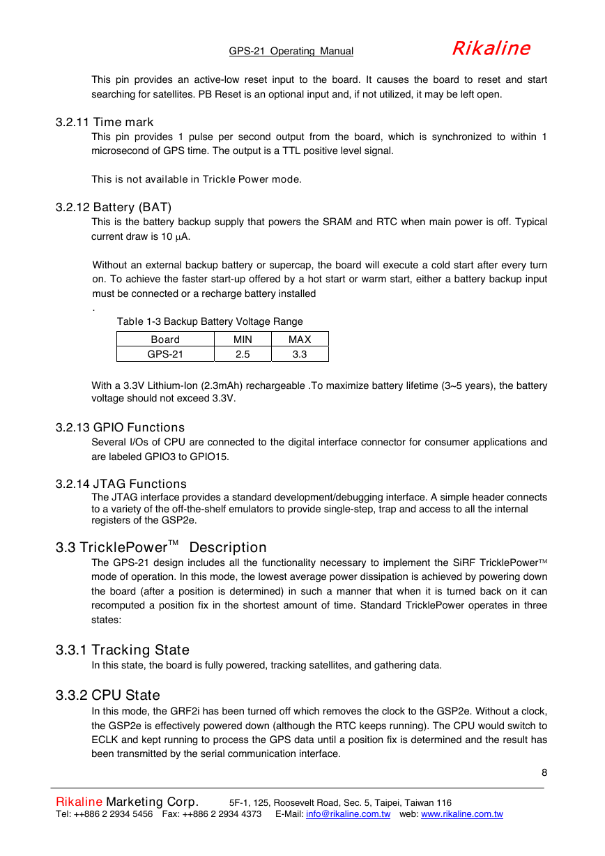
Table 1-3 Backup Battery Voltage Range
Board
GPS-21
MIN
2.5
MAX
3.3
With a 3.3V Lithium-Ion (2.3mAh) rechargeable .To maximize battery lifetime (3~5 years), the battery
voltage should not exceed 3.3V.
3.2.13 GPIO Functions
Several I/Os of CPU are connected to the digital interface connector for consumer applications and
are labeled GPIO3 to GPIO15.
3.2.14 JTAG Functions
The JTAG interface provides a standard development/debugging interface. A simple header connects
to a variety of the off-the-shelf emulators to provide single-step, trap and access to all the internal
registers of the GSP2e.
3.3 TricklePowerTM
Description
The GPS-21 design includes all the functionality necessary to implement the SiRF TricklePower
mode of operation. In this mode, the lowest average power dissipation is achieved by powering down
the board (after a position is determined) in such a manner that when it is turned back on it can
recomputed a position fix in the shortest amount of time. Standard TricklePower operates in three
states:
3.3.1 Tracking State
In this state, the board is fully powered, tracking satellites, and gathering data.
3.3.2 CPU State
In this mode, the GRF2i has been turned off which removes the clock to the GSP2e. Without a clock,
the GSP2e is effectively powered down (although the RTC keeps running). The CPU would switch to
ECLK and kept running to process the GPS data until a position fix is determined and the result has
been transmitted by the serial communication interface.
Rikaline Marketing Corp.
Tel: ++886 2 2934 5456 Fax: ++886 2 2934 4373 E-Mail: info@rikaline.com.tw web: www.rikaline.com.tw
5F-1, 125, Roosevelt Road, Sec. 5, Taipei, Taiwan 116
8
�



 2023年江西萍乡中考道德与法治真题及答案.doc
 2012年重庆南川中考生物真题及答案.doc
 2013年江西师范大学地理学综合及文艺理论基础考研真题.doc
 2020年四川甘孜小升初语文真题及答案I卷.doc
 2020年注册岩土工程师专业基础考试真题及答案.doc
 2023-2024学年福建省厦门市九年级上学期数学月考试题及答案.doc
 2021-2022学年辽宁省沈阳市大东区九年级上学期语文期末试题及答案.doc
 2022-2023学年北京东城区初三第一学期物理期末试卷及答案.doc
 2018上半年江西教师资格初中地理学科知识与教学能力真题及答案.doc
 2012年河北国家公务员申论考试真题及答案-省级.doc
 2020-2021学年江苏省扬州市江都区邵樊片九年级上学期数学第一次质量检测试题及答案.doc
 2022下半年黑龙江教师资格证中学综合素质真题及答案.doc