�
Raspberry Pi Compute Module 4
Colophon
© 2020-2023 Raspberry Pi Ltd (formerly Raspberry Pi (Trading) Ltd.)
The documentation around the Raspberry Pi Compute Module 4 is licensed under a Creative Commons Attribution-
NoDerivatives 4.0 International (CC BY-ND).
build-date: 2023-11-07
build-version: githash: 752a7dd-dirty
Legal disclaimer notice
TECHNICAL AND RELIABILITY DATA FOR RASPBERRY PI PRODUCTS (INCLUDING DATASHEETS) AS MODIFIED FROM
TIME TO TIME (“RESOURCES”) ARE PROVIDED BY RASPBERRY PI LTD (“RPL”) "AS IS" AND ANY EXPRESS OR IMPLIED
WARRANTIES, INCLUDING, BUT NOT LIMITED TO, THE IMPLIED WARRANTIES OF MERCHANTABILITY AND FITNESS
FOR A PARTICULAR PURPOSE ARE DISCLAIMED. TO THE MAXIMUM EXTENT PERMITTED BY APPLICABLE LAW IN NO
EVENT SHALL RPL BE LIABLE FOR ANY DIRECT, INDIRECT, INCIDENTAL, SPECIAL, EXEMPLARY, OR CONSEQUENTIAL
DAMAGES (INCLUDING, BUT NOT LIMITED TO, PROCUREMENT OF SUBSTITUTE GOODS OR SERVICES; LOSS OF USE,
DATA, OR PROFITS; OR BUSINESS INTERRUPTION) HOWEVER CAUSED AND ON ANY THEORY OF LIABILITY, WHETHER
IN CONTRACT, STRICT LIABILITY, OR TORT (INCLUDING NEGLIGENCE OR OTHERWISE) ARISING IN ANY WAY OUT OF
THE USE OF THE RESOURCES, EVEN IF ADVISED OF THE POSSIBILITY OF SUCH DAMAGE.
RPL reserves the right to make any enhancements, improvements, corrections or any other modifications to the
RESOURCES or any products described in them at any time and without further notice.
The RESOURCES are intended for skilled users with suitable levels of design knowledge. Users are solely responsible for
their selection and use of the RESOURCES and any application of the products described in them. User agrees to
indemnify and hold RPL harmless against all liabilities, costs, damages or other losses arising out of their use of the
RESOURCES.
RPL grants users permission to use the RESOURCES solely in conjunction with the Raspberry Pi products. All other use
of the RESOURCES is prohibited. No licence is granted to any other RPL or other third party intellectual property right.
HIGH RISK ACTIVITIES. Raspberry Pi products are not designed, manufactured or intended for use in hazardous
environments requiring fail safe performance, such as in the operation of nuclear facilities, aircraft navigation or
communication systems, air traffic control, weapons systems or safety-critical applications (including life support
systems and other medical devices), in which the failure of the products could lead directly to death, personal injury or
severe physical or environmental damage (“High Risk Activities”). RPL specifically disclaims any express or implied
warranty of fitness for High Risk Activities and accepts no liability for use or inclusions of Raspberry Pi products in High
Risk Activities.
Raspberry Pi products are provided subject to RPL’s Standard Terms. RPL’s provision of the RESOURCES does not
expand or otherwise modify RPL’s Standard Terms including but not limited to the disclaimers and warranties
expressed in them.
Legal disclaimer notice
1
Raspberry Pi Compute Module 4
Table of contents
Colophon . . . . . . . . . . . . . . . . . . . . . . . . . . . . . . . . . . . . . . . . . . . . . . . . . . . . . . . . . . . . . . . . . . . . . . . . . . . . . . . . . . . . . . . . . . . . . . 1
Legal disclaimer notice . . . . . . . . . . . . . . . . . . . . . . . . . . . . . . . . . . . . . . . . . . . . . . . . . . . . . . . . . . . . . . . . . . . . . . . . . . . . . . . 1
1. Introduction. . . . . . . . . . . . . . . . . . . . . . . . . . . . . . . . . . . . . . . . . . . . . . . . . . . . . . . . . . . . . . . . . . . . . . . . . . . . . . . . . . . . . . . . . . 3
1.1. Introduction . . . . . . . . . . . . . . . . . . . . . . . . . . . . . . . . . . . . . . . . . . . . . . . . . . . . . . . . . . . . . . . . . . . . . . . . . . . . . . . . . . . . . 3
1.2. Features . . . . . . . . . . . . . . . . . . . . . . . . . . . . . . . . . . . . . . . . . . . . . . . . . . . . . . . . . . . . . . . . . . . . . . . . . . . . . . . . . . . . . . . . 3
2. Interfaces . . . . . . . . . . . . . . . . . . . . . . . . . . . . . . . . . . . . . . . . . . . . . . . . . . . . . . . . . . . . . . . . . . . . . . . . . . . . . . . . . . . . . . . . . . . 5
2.1. Wireless . . . . . . . . . . . . . . . . . . . . . . . . . . . . . . . . . . . . . . . . . . . . . . . . . . . . . . . . . . . . . . . . . . . . . . . . . . . . . . . . . . . . . . . . 5
2.1.1. WL_nDisable. . . . . . . . . . . . . . . . . . . . . . . . . . . . . . . . . . . . . . . . . . . . . . . . . . . . . . . . . . . . . . . . . . . . . . . . . . . . . . . . . . 5
2.1.2. BT_nDisable. . . . . . . . . . . . . . . . . . . . . . . . . . . . . . . . . . . . . . . . . . . . . . . . . . . . . . . . . . . . . . . . . . . . . . . . . . . . . . . . . . 5
2.2. Ethernet . . . . . . . . . . . . . . . . . . . . . . . . . . . . . . . . . . . . . . . . . . . . . . . . . . . . . . . . . . . . . . . . . . . . . . . . . . . . . . . . . . . . . . . . 6
2.3. PCIe (Gen2 x1). . . . . . . . . . . . . . . . . . . . . . . . . . . . . . . . . . . . . . . . . . . . . . . . . . . . . . . . . . . . . . . . . . . . . . . . . . . . . . . . . . . 6
2.4. USB 2.0 (high speed) . . . . . . . . . . . . . . . . . . . . . . . . . . . . . . . . . . . . . . . . . . . . . . . . . . . . . . . . . . . . . . . . . . . . . . . . . . . . . 7
2.5. GPIO . . . . . . . . . . . . . . . . . . . . . . . . . . . . . . . . . . . . . . . . . . . . . . . . . . . . . . . . . . . . . . . . . . . . . . . . . . . . . . . . . . . . . . . . . . . 7
2.5.1. Alternative function assignments . . . . . . . . . . . . . . . . . . . . . . . . . . . . . . . . . . . . . . . . . . . . . . . . . . . . . . . . . . . . . . 8
2.6. Dual HDMI 2.0 . . . . . . . . . . . . . . . . . . . . . . . . . . . . . . . . . . . . . . . . . . . . . . . . . . . . . . . . . . . . . . . . . . . . . . . . . . . . . . . . . . 10
2.7. CSI-2 (MIPI serial camera) . . . . . . . . . . . . . . . . . . . . . . . . . . . . . . . . . . . . . . . . . . . . . . . . . . . . . . . . . . . . . . . . . . . . . . . . 11
2.8. DSI (MIPI serial display) . . . . . . . . . . . . . . . . . . . . . . . . . . . . . . . . . . . . . . . . . . . . . . . . . . . . . . . . . . . . . . . . . . . . . . . . . . 11
2.9. I2C (SDA0 SCL0) . . . . . . . . . . . . . . . . . . . . . . . . . . . . . . . . . . . . . . . . . . . . . . . . . . . . . . . . . . . . . . . . . . . . . . . . . . . . . . . . 11
2.10. I2C (ID_SD ID_SC) . . . . . . . . . . . . . . . . . . . . . . . . . . . . . . . . . . . . . . . . . . . . . . . . . . . . . . . . . . . . . . . . . . . . . . . . . . . . . . 11
2.11. SDIO/eMMC (CM4Lite only) . . . . . . . . . . . . . . . . . . . . . . . . . . . . . . . . . . . . . . . . . . . . . . . . . . . . . . . . . . . . . . . . . . . . . 11
2.12. Analog IP0/IP1 . . . . . . . . . . . . . . . . . . . . . . . . . . . . . . . . . . . . . . . . . . . . . . . . . . . . . . . . . . . . . . . . . . . . . . . . . . . . . . . . 12
2.13. Global_EN. . . . . . . . . . . . . . . . . . . . . . . . . . . . . . . . . . . . . . . . . . . . . . . . . . . . . . . . . . . . . . . . . . . . . . . . . . . . . . . . . . . . . . 12
2.14. RUN_PG . . . . . . . . . . . . . . . . . . . . . . . . . . . . . . . . . . . . . . . . . . . . . . . . . . . . . . . . . . . . . . . . . . . . . . . . . . . . . . . . . . . . . . . . 12
2.15. nRPI_BOOT. . . . . . . . . . . . . . . . . . . . . . . . . . . . . . . . . . . . . . . . . . . . . . . . . . . . . . . . . . . . . . . . . . . . . . . . . . . . . . . . . . . . . . 12
2.16. LED_nACT. . . . . . . . . . . . . . . . . . . . . . . . . . . . . . . . . . . . . . . . . . . . . . . . . . . . . . . . . . . . . . . . . . . . . . . . . . . . . . . . . . . . . . . 13
2.17. LED_nPWR. . . . . . . . . . . . . . . . . . . . . . . . . . . . . . . . . . . . . . . . . . . . . . . . . . . . . . . . . . . . . . . . . . . . . . . . . . . . . . . . . . . . . . . 13
2.18. EEPROM_nWP . . . . . . . . . . . . . . . . . . . . . . . . . . . . . . . . . . . . . . . . . . . . . . . . . . . . . . . . . . . . . . . . . . . . . . . . . . . . . . . . . . . . . 13
3. Electrical and mechanical . . . . . . . . . . . . . . . . . . . . . . . . . . . . . . . . . . . . . . . . . . . . . . . . . . . . . . . . . . . . . . . . . . . . . . . . . . . . . 14
3.1. Mechanical . . . . . . . . . . . . . . . . . . . . . . . . . . . . . . . . . . . . . . . . . . . . . . . . . . . . . . . . . . . . . . . . . . . . . . . . . . . . . . . . . . . . 14
3.2. Thermal . . . . . . . . . . . . . . . . . . . . . . . . . . . . . . . . . . . . . . . . . . . . . . . . . . . . . . . . . . . . . . . . . . . . . . . . . . . . . . . . . . . . . . . 15
3.3. Electrical specification . . . . . . . . . . . . . . . . . . . . . . . . . . . . . . . . . . . . . . . . . . . . . . . . . . . . . . . . . . . . . . . . . . . . . . . . . . . 15
4. Pinout . . . . . . . . . . . . . . . . . . . . . . . . . . . . . . . . . . . . . . . . . . . . . . . . . . . . . . . . . . . . . . . . . . . . . . . . . . . . . . . . . . . . . . . . . . . . . 17
4.1. Differential pairs . . . . . . . . . . . . . . . . . . . . . . . . . . . . . . . . . . . . . . . . . . . . . . . . . . . . . . . . . . . . . . . . . . . . . . . . . . . . . . . . 24
4.1.1. 100Ω differential pair signal lengths . . . . . . . . . . . . . . . . . . . . . . . . . . . . . . . . . . . . . . . . . . . . . . . . . . . . . . . . . . . 24
4.1.2. 90Ω differential pair signal lengths . . . . . . . . . . . . . . . . . . . . . . . . . . . . . . . . . . . . . . . . . . . . . . . . . . . . . . . . . . . . 26
5. Power. . . . . . . . . . . . . . . . . . . . . . . . . . . . . . . . . . . . . . . . . . . . . . . . . . . . . . . . . . . . . . . . . . . . . . . . . . . . . . . . . . . . . . . . . . . . . . 27
5.1. Power-up sequencing. . . . . . . . . . . . . . . . . . . . . . . . . . . . . . . . . . . . . . . . . . . . . . . . . . . . . . . . . . . . . . . . . . . . . . . . . . . . 27
5.2. Power-down sequencing . . . . . . . . . . . . . . . . . . . . . . . . . . . . . . . . . . . . . . . . . . . . . . . . . . . . . . . . . . . . . . . . . . . . . . . . . 27
5.3. Power consumption . . . . . . . . . . . . . . . . . . . . . . . . . . . . . . . . . . . . . . . . . . . . . . . . . . . . . . . . . . . . . . . . . . . . . . . . . . . . . 27
5.4. Regulator outputs . . . . . . . . . . . . . . . . . . . . . . . . . . . . . . . . . . . . . . . . . . . . . . . . . . . . . . . . . . . . . . . . . . . . . . . . . . . . . . . 27
Appendix A: Troubleshooting . . . . . . . . . . . . . . . . . . . . . . . . . . . . . . . . . . . . . . . . . . . . . . . . . . . . . . . . . . . . . . . . . . . . . . . . . . . . 28
Hardware checklist. . . . . . . . . . . . . . . . . . . . . . . . . . . . . . . . . . . . . . . . . . . . . . . . . . . . . . . . . . . . . . . . . . . . . . . . . . . . . . . . . . 28
Bootloader. . . . . . . . . . . . . . . . . . . . . . . . . . . . . . . . . . . . . . . . . . . . . . . . . . . . . . . . . . . . . . . . . . . . . . . . . . . . . . . . . . . . . . . . . 28
rpi-eeprom-update . . . . . . . . . . . . . . . . . . . . . . . . . . . . . . . . . . . . . . . . . . . . . . . . . . . . . . . . . . . . . . . . . . . . . . . . . . . . . . . . . . 28
EEPROM write-protect . . . . . . . . . . . . . . . . . . . . . . . . . . . . . . . . . . . . . . . . . . . . . . . . . . . . . . . . . . . . . . . . . . . . . . . . . . . . . . . 28
Firmware . . . . . . . . . . . . . . . . . . . . . . . . . . . . . . . . . . . . . . . . . . . . . . . . . . . . . . . . . . . . . . . . . . . . . . . . . . . . . . . . . . . . . . . . . . 29
Kernel. . . . . . . . . . . . . . . . . . . . . . . . . . . . . . . . . . . . . . . . . . . . . . . . . . . . . . . . . . . . . . . . . . . . . . . . . . . . . . . . . . . . . . . . . . . . . 29
Appendix B: Availability . . . . . . . . . . . . . . . . . . . . . . . . . . . . . . . . . . . . . . . . . . . . . . . . . . . . . . . . . . . . . . . . . . . . . . . . . . . . . . . . . 30
Support . . . . . . . . . . . . . . . . . . . . . . . . . . . . . . . . . . . . . . . . . . . . . . . . . . . . . . . . . . . . . . . . . . . . . . . . . . . . . . . . . . . . . . . . . . . 30
Ordering codes . . . . . . . . . . . . . . . . . . . . . . . . . . . . . . . . . . . . . . . . . . . . . . . . . . . . . . . . . . . . . . . . . . . . . . . . . . . . . . . . . . . . . 30
Packaging . . . . . . . . . . . . . . . . . . . . . . . . . . . . . . . . . . . . . . . . . . . . . . . . . . . . . . . . . . . . . . . . . . . . . . . . . . . . . . . . . . . . . . . . . 31
Table of contents
2
�
Raspberry Pi Compute Module 4
Chapter 1. Introduction
1.1. Introduction
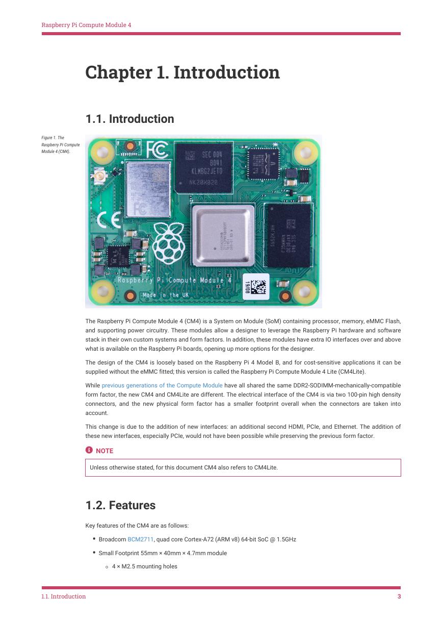
Figure 1. The
Raspberry Pi Compute
Module 4 (CM4).
The Raspberry Pi Compute Module 4 (CM4) is a System on Module (SoM) containing processor, memory, eMMC Flash,
and supporting power circuitry. These modules allow a designer to leverage the Raspberry Pi hardware and software
stack in their own custom systems and form factors. In addition, these modules have extra IO interfaces over and above
what is available on the Raspberry Pi boards, opening up more options for the designer.
The design of the CM4 is loosely based on the Raspberry Pi 4 Model B, and for cost-sensitive applications it can be
supplied without the eMMC fitted; this version is called the Raspberry Pi Compute Module 4 Lite (CM4Lite).
While previous generations of the Compute Module have all shared the same DDR2-SODIMM-mechanically-compatible
form factor, the new CM4 and CM4Lite are different. The electrical interface of the CM4 is via two 100-pin high density
connectors, and the new physical form factor has a smaller footprint overall when the connectors are taken into
account.
This change is due to the addition of new interfaces: an additional second HDMI, PCIe, and Ethernet. The addition of
these new interfaces, especially PCIe, would not have been possible while preserving the previous form factor.
NOTE
Unless otherwise stated, for this document CM4 also refers to CM4Lite.
1.2. Features
Key features of the CM4 are as follows:
• Broadcom BCM2711, quad core Cortex-A72 (ARM v8) 64-bit SoC @ 1.5GHz
• Small Footprint 55mm × 40mm × 4.7mm module
◦ 4 × M2.5 mounting holes
1.1. Introduction
3
�
Raspberry Pi Compute Module 4
• H.265 (HEVC) (upto 4Kp60 decode), H.264 (upto 1080p60 decode, 1080p30 encode)
• OpenGL ES 3.0 graphics
• Options for 1GB, 2GB, 4GB or 8GB LPDDR4-3200 SDRAM with ECC (see Appendix B)
• Options for 0GB (CM4Lite), 8GB, 16GB, or 32GB eMMC flash memory (see Appendix B)
◦ Peak eMMC bandwidth 100MBps (four times faster than previous Compute Modules)
• Option (see Appendix B) for certified radio module with:
◦ 2.4 GHz, 5.0 GHz IEEE 802.11 b/g/n/ac wireless
◦ Bluetooth 5.0, BLE
◦ On board electronic switch to select between PCB trace or external antenna
• Gigabit Ethernet PHY supporting IEEE 1588
• 1 × PCIe 1-lane Host, Gen 2 (5Gbps)
• 1 × USB 2.0 port (high speed)
• 28 × GPIO supporting either 1.8V or 3.3V signalling and peripheral options:
◦ Up to 5 × UART
◦ Up to 5 × I2C
◦ Up to 5 × SPI
◦ 1 × SDIO interface
◦ 1 × DPI (parallel RGB display)
◦ 1 × PCM
◦ Up to 2× PWM channels
◦ Up to 3× GPCLK outputs
• 1 × SDIO 2.0 (CM4Lite)
• Single +5V PSU input.
• 2 × HDMI 2.0 ports (up to 4Kp60 supported)
• MIPI DSI:
◦ 1 × 2-lane MIPI DSI display port
◦ 1 × 4-lane MIPI DSI display port
• MIPI CSI-2:
◦ 1 × 2-lane MIPI CSI camera port
◦ 1 × 4-lane MIPI CSI camera port
1.2. Features
4
�
Raspberry Pi Compute Module 4
Chapter 2. Interfaces
2.1. Wireless
The CM4 can be supplied with an on-board wireless module based on the Cypress CYW43455 supporting both:
• 2.4 GHz, 5.0 GHz IEEE 802.11 b/g/n/ac wireless
• Bluetooth 5.0, BLE
These wireless interfaces can be individually enabled or disabled as required. For instance, in the case of a kiosk
application, a service engineer could enable wireless operation and then disable it once finished.
The CM4 has an on-board antenna. If used it should be positioned in the product such that it is not surrounded by metal,
including any ground plane (see Chapter 3 for further details). Alternatively there is a standard U.FL connector on the
module, see Figure 1, so that an external antenna can be used.
Raspberry Pi Ltd has an antenna kit which is certified to be used with the CM4. If a different antenna is used then
separate certification will be required.
WARNING
Raspberry Pi Ltd will not be able to assist with certification for third-party antennas.
The selection of internal or external antenna is done at boot time using the config.txt file, and can not be changed
during operation. The config.txt options are dtparam=ant1 to select the internal antenna, or dtparam=ant2 for the external
antenna.
2.1.1. WL_nDisable
This pin serves a number of functions;
1. It can be used to monitor the enable/disable state of wireless networking. A logic high means the wireless
networking module is powered up.
2. When driven or tied low it prevents the wireless network module from powering up. This is useful to reduce power
consumption or in applications where it is required to physically ensure the wireless networking is disabled. If the
interface is enabled after being disabled, the wireless interface driver needs reinitialised.
NOTE
On CM4 modules without wireless, this pin is reserved.
2.1.2. BT_nDisable
This pin serves a number of functions;
1. It can be used to monitor the enable/disable state of Bluetooth. A logic high means the Bluetooth module is
powered up.
2. When driven, or tied low, it prevents the Bluetooth module from powering up. This is useful to reduce power
consumption, or in applications where it is required to physically ensure the Bluetooth is disabled. If the interface is
enabled after being disabled, the Bluetooth interface driver needs reinitialised.
2.1. Wireless
5
�
Raspberry Pi Compute Module 4
NOTE
On CM4 modules without wireless, this pin is reserved.
2.2. Ethernet
The CM4 has an on-board Gigabit Ethernet PHY — the Broadcom BCM54210PE — some of the major features of this
PHY include;
• IEEE 1588-2008 compliant
• MDI crossover, pair skew and pair polarity correction
A standard 1:1 RJ45 MagJack is all that is necessary to provide an Ethernet connection to the CM4. Typical wiring of a
MagJack supporting PoE, and with added ESD protection, can be seen in Figure 2.
Figure 2. Ethernet
schematic interface
for the Raspberry Pi
Compute Module 4
supporting PoE, and
with added ESD
protection.
The differential Ethernet signals should be routed as 100Ω differential pairs, with suitable clearances. Length matching
between pairs should be better than 50mm, so in the typical case no length matching is required. However the signals
within a pair need to be length matched, ideally to better than 0.15mm.
The PHY also supports up to 3 LEDs to give user status feedback, these are low active. These LEDs can have a range of
functions, and you should consult your OS driver to see which functions are supported by your driver.
The PHY also provides SYNC_IN and SYNC_OUT at 3.3V signalling to support IEEE 1588-2008.
2.3. PCIe (Gen2 x1)
The CM4 has an internal PCIe 2.0 x1 host controller. While on the Raspberry Pi 4 Model B this has been connected to a
USB 3 host controller (using the Via Labs VLI805), on the CM4 the product designer is free to choose how the interface
is used.
2.2. Ethernet
6
�
Raspberry Pi Compute Module 4
WARNING
You should ensure that there is a suitable OS driver for any host controller that is chosen before proceeding to a
prototype.
NOTE
The on-board PCIe Host controller doesn’t support 64-bit accesses from the ARM, they must be split up into two 32-
bit accesses.
Connecting a PCIe device follows the standard PCIe convention. The CM4 has on-board AC coupling capacitors for CLK
and PCIe_TX signals. However the PCIe_RX signals need external coupling capacitors close to the driving source (the
device TX), if you are using an external PCIe/NVMe card these capacitors will be on-board. The PCIe convention is that if
you are wiring directly to an IC then the TX and RX pairs need to be swapped (i.e. TX → RX, RX → TX). If you are wiring
to a connector then this is typically labelled from the host point of view and so TX/RX swaps aren’t required.
Additionally the PCIe_CLK_nREQ must be connected to ensure the CM4 produces a clock signal, and the PCIe_nRST should
also be connected to ensure the device is correctly reset when required.
The differential PCIe signals should be routed as 90Ω differential pairs, with suitable clearances. There is no need to
match the lengths between pairs, only the signals within a Pair need to be length matched ideally to better than 0.1mm.
TIP
5.10 kernels and newer have had support for MSI-X added. There is a limit of upto 32 IRQs available. If the device
has problems with interrupts then adding pci=nomsi to cmdline.txt (and rebooting) often fixes the issue.
2.4. USB 2.0 (high speed)
The USB 2.0 interface supports up to 480Mbps signalling. The differential pair should be routed as a 90Ω differential
pair. The length of the P/N signals should ideally be matched to better than 0.15mm.
TIP
The firmware disables the USB interface by default to save power. In recent versions of Raspberry Pi OS (Bullseye) it
is automatically enabled by the otg_mode=1 setting in the config.txt file. If you are using a different OS, or an older
version of Raspberry Pi OS, you will need to add this to config.txt to enable the USB interface.
NOTE
The port is capable of being used as a true USB On-The-Go (OTG) port. While there is no official documentation,
some users have had success making this work. The USB_OTG_ID pin is used to select between USB host and device
that is typically wired to the ID pin of a Micro USB connector. To use this functionality it must be enabled in the OS. If
using either as a fixed slave or fixed master, please tie the USB_OTG_ID pin to ground.
2.5. GPIO
There are 28 pins available for general purpose I/O (GPIO), which correspond to the GPIO pins on the Raspberry Pi 4
Model B 40-pin header. These pins have access to internal peripherals: SMI, DPI, I2C, PWM, SPI, and UART. The
BCM2711 ARM peripherals book describes these features in detail, along with the multiplexing options available. The
drive strength and slew rate should ideally be set as low as possible to reduce any EMC issues. GPIO2 and GPIO3 have
1.8kΩ pull up resistors.
The BCM2711 GPIO bank is powered by GPIO_VREF, this can either be connected to +1.8V for 1.8V signalling GPIO, or
2.4. USB 2.0 (high speed)
7
�




 V2版本原理图(Capacitive-Fingerprint-Reader-Schematic_V2).pdf
 摄像头工作原理.doc
 VL53L0X简要说明(En.FLVL53L00216).pdf
 原理图(DVK720-Schematic).pdf
 原理图(Pico-Clock-Green-Schdoc).pdf
 原理图(RS485-CAN-HAT-B-schematic).pdf
 File:SIM7500_SIM7600_SIM7800 Series_SSL_Application Note_V2.00.pdf
 ADS1263(Ads1262).pdf
 原理图(Open429Z-D-Schematic).pdf
 用户手册(Capacitive_Fingerprint_Reader_User_Manual_CN).pdf
 CY7C68013A(英文版)(CY7C68013A).pdf
 TechnicalReference_Dem.pdf