logo资料库

MXM标准协议.pdf

第1页 / 共73页
第2页 / 共73页
第3页 / 共73页
第4页 / 共73页
第5页 / 共73页
第6页 / 共73页
第7页 / 共73页
第8页 / 共73页
资料共73页,剩余部分请下载后查看
Contents
1 Introduction
1.1 Background
1.2 MXM Version 3.0 Benefits
1.3 Display Support
1.4 Required/Optional Feature Matrix
2 Mechanical Specification
2.1 Form Factors
2.2 MXM Board Outlines
2.3 MXM PCB Mounting Holes
2.3.1 Board Mounting Holes
2.3.2 Thermal Solution Mounting
2.3.3 Backing Plate
2.4 Board Height Restrictions
2.5 MXM Edge Fingers
2.6 MXM Connector
3 Electrical Specifications
3.1 Electrical Connector
3.2 Connector Pinout
3.3 Pin Description
3.3.1 Power Group
3.3.2 PCI Express Signal Group
3.3.3 DisplayPort Signal Group
3.3.4 LVDS Signal Group
3.3.5 Analog Display Signal Group
3.3.6 Power and Thermal Management Signal Group
3.3.7 System Management Signal Group
3.4 System Requirements
3.4.1 Power Sequencing
3.4.2 Module Power Down and Power Up
3.4.3 Reset Requirements
3.4.4 PCI Express Interface
3.4.5 DisplayPort Interface
3.4.6 DVI/HDMI on DP Interface
3.4.7 DVI/HDMI on LVDS Interface
3.4.8 VGA Interface
3.4.9 TV Out Implementation
3.4.10 SMBus interface
3.4.11 Thermal and Power Management Interface
3.4.12 PWR_LEVEL Signal
3.4.13 Internal Flat Panel Interface
3.4.14 VGA_DISABLE# Signal
3.4.15 WAKE Functionality
3.4.16 OEM Modules
3.5 Signal Integrity
3.5.1 Module Specification
3.5.2 System Specification
3.5.3 DisplayPort
3.5.4 TMDS and LVDS
3.5.5 PCI Express
3.6 DC Specifications
4 Thermal Specification
4.1 Thermal Specification Philosophy
4.1.1 System Thermal Components
4.1.2 Power Sources
4.2 Thermal Requirements
4.2.1 System Requirements
4.2.2 Module Thermal Requirements
4.2.3 Thermal Solution Requirements
4.3 Thermal Specification Summary
Applicable Documents
Mobile PCI Express Module Electromechanical Specification Version 3.0 Revision 1.0 June 26, 2008
Revision History Rev Resp GG 1.0 Change Initial release. iii
iv
Contents 1 Introduction . 1.1 Background . . 1.2 MXM Version 3.0 Benefits . . 1.3 Display Support . 1.4 Required/Optional Feature Matrix . . . . . . . . . . . . . . . . . . . . . . . . . . . . . . . . . . . . Form Factors . 2 Mechanical Specification . . . . . 2.1 . 2.2 MXM Board Outlines . . 2.3 MXM PCB Mounting Holes . Board Mounting Holes . Thermal Solution Mounting . . Backing Plate . . . . 2.4 Board Height Restrictions . . 2.5 MXM Edge Fingers 2.6 MXM Connector . . 2.3.1 2.3.2 2.3.3 . . . . . . . . . . . . . . . . . . . . . . . . . . . . . . . . . . . . . . . . . . . . . . . . . . . . . . . . . . . . . . . . . . . . . . . . . . . . . . . . . . . . . . . . . . . . . . . . . . . . . . . . . . . . . . . . . . . . . . . . . . . . . . . . . . . . . . . . . . . . . . . . . . . . . . . . . . . . . . . . . . . . . . . . . . . . . . . . . . . . . . . . . . . . . . . . . . . . . . . . . . . . . . . . . . . . . . . . . . . . . . . . . . . . . . . . . . . . . . . . . . . . . . . . . . . . . . . . . . . . . . . . . . . . . . . . . . 3 Electrical Specifications . . . . . . Power Group . . PCI Express Signal Group . . . 3.1 Electrical Connector . . 3.2 Connector Pinout Pin Description . 3.3 . 3.3.1 3.3.2 3.3.3 DisplayPort Signal Group . 3.3.4 . 3.3.5 3.3.6 . 3.3.7 . System Requirements . 3.4.1 . 3.4.2 Module Power Down and Power Up . . . . Reset Requirements . . 3.4.3 . . . 3.4.4 PCI Express Interface . . . 3.4.5 DisplayPort Interface . . . 3.4.6 DVI/HDMI on DP Interface . . . 3.4.7 DVI/HDMI on LVDS Interface . . . 3.4.8 3.4.9 . . . . . . . . . . . . . . . LVDS Signal Group . . Analog Display Signal Group . . Power and Thermal Management Signal Group . . System Management Signal Group . . . . . . . . . . . . . VGA Interface . . TV Out Implementation . . Power Sequencing . . . . . . . . . . . . . . . . . . . . . . . . . . . . . . . . . . . . . . . . . . . . . . . . . . . . . . . . . . . . . . . 3.4 . . . . . . . . . . . . . . . . . . . . . . . . . . . . . . . . . . . . . . . . . . . . . . . . . . . . . . . . . . . . . . . . . . . . . . . . . . . . . . . . . . . . . . . . . . . . . . . . . . . . . . . . . . . . . . . . . . . . . . . . . . . . . . . . . . . . . . . . . . . . . . . . . . . . . . . . . . . . . . . . . . . . . . . . . . . . . . . . . . . . . . . . . . . . . . . . . . . . . . . . . . . . . . . . . . . . . . . . . . . . . . . . . . . . . . . . . . . . . . . . . . . . . . . . . . . . . . . . . . . . . . . . . . . . . . . . . . . . . . . . . . . . . . . . . . . . . . . . . . . . . . . . . . . . . . . . . . . . . . . . . . . . . . . . . . . . . . . . . . . . . . . . . . . . . . . . . . . . . . . . . . . . . . . . . . . . . . . . . . . . . . . . . . . . . . . . . . . . . . . . . . . . . . . . . . . . . . . . . . . . . . . . . . . . . . . . . . . . . . . . . . . . . . . . . . . . . . . . . . . . . . . . . . . . . . . . . . . . . . . . . . . . . . . . . . . . . . . . . . . . . . . . . . . . . . . . . . . . . . . . . . . . . . . . . . . . . . . . . . . . 1 1 2 3 4 5 5 5 7 7 7 7 9 14 19 23 23 25 28 28 29 30 31 32 33 34 35 35 36 36 37 37 38 39 39 40 v
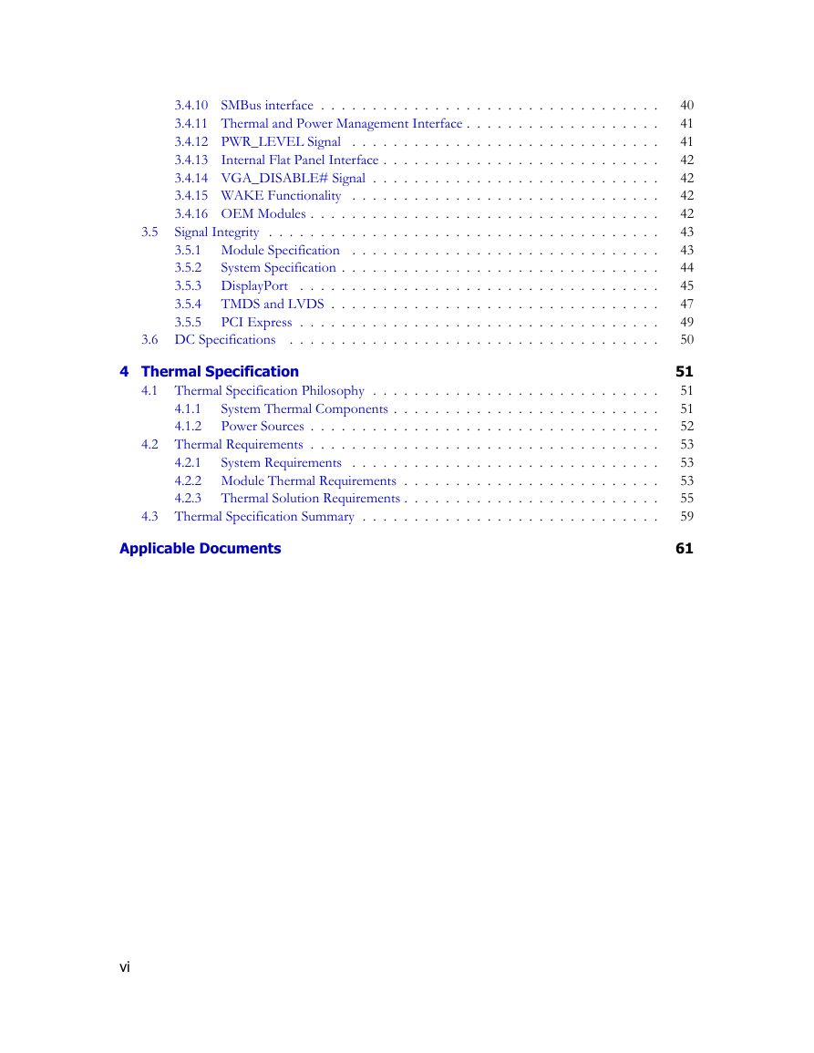
. . . . . . . . . . . . . . 3.4.10 SMBus interface . . 3.4.11 Thermal and Power Management Interface . . 3.4.12 PWR_LEVEL Signal . . 3.4.13 Internal Flat Panel Interface . 3.4.14 VGA_DISABLE# Signal . . . . . 3.4.15 WAKE Functionality . . . . . 3.4.16 OEM Modules . Signal Integrity . . . . . . . . . 3.5.1 Module Specification . . . . . 3.5.2 . . . . 3.5.3 DisplayPort 3.5.4 . . . . . . . . 3.5.5 . . . . System Specification . . . . . . TMDS and LVDS . . PCI Express . . . . . . . . . . . . . . . . . . . . . . . . . . . . . . . . . . . . . . . . . . . . . . . . . . . . . . . . . . . . . . . . . . . . . . . . . . . . . . . . . . . . . . . . . . . . . . . . . . . . . . . . . . . . . . . . . 3.6 DC Specifications . 3.5 . . . . . . . . . . . . . . . . . . . . . . . . . . . . . . . . . . . . . . . . . . . . . . . . . . . . . . . . . . . . . . . . . . . . . . . . . . . . . . . . . . . . . . . . . . . . . . . . . . . . . . . . . . . . . . . . . . . . . . . . . . . . . . . . . . . . . . . . . . . . . . . . . . . . . . . . . . . . . . . . . . . . . . . . . . . . . . . . . . . . . . . . . . . . . . . . . . . . . . . . . . . . . . . . . . . . . . . . . . . . . . . . . . . . . . . . . . . . . . . . . . . . . . . . . . . . . . . . . . . . . . . . . . . . . . . . . . . . . . . . . . . . . . . . . . . . . . . . . . . . . . . . . . . . . . . . . . . . . . . . . . . . . . . . . . . . . . . . . . . . . . . . . . . . . . . . . . . . . . . . . . . . . . . . . . . . . . . . . . . . . . . . . . . . . . . . . . . . . . 40 41 41 42 42 42 42 43 43 44 45 47 49 50 51 51 51 52 53 53 53 55 59 61 4 Thermal Specification . 4.1.1 4.1.2 4.1 Thermal Specification Philosophy . . System Thermal Components . . Power Sources . 4.2 Thermal Requirements . . . . . . . 4.2.1 . 4.2.2 Module Thermal Requirements . 4.2.3 Thermal Solution Requirements . . . . System Requirements . 4.3 Thermal Specification Summary . . . . . . . . . . . . . . . . . . . . . . . . . . . . . . . . . . . . . . . . . . . . . . . . . . . . . . . . . . . . . . . . . . . Applicable Documents vi
List of Figures 1.1 MXM Applications . . 1.2 MXM Compatibility . . . . . . . . . . . . . . . . . . . . . . . . . . . . . . . . . . . . . . . . . . . . . . . . . . . . . . . . . . . . . . . . . . . . . . . . . . . . . . . . . . . . . . . . . . . . . 2.1 Board Outlines . . . 2.2 Board Slots Detail . 2.3 Mounting Holes (Type A and Type B) . . 2.4 Board Bottom Side Height Restrictions (Type A and Type B) . 2.5 Type A Top Side Height Restrictions . . . 2.6 Type B Top Side Height Restrictions . . . 2.7 Card Thickness and Chamfer . . . 2.8 Module Edge Finger Top . . . 2.9 Module Edge Finger Bottom . . . . 2.10 Pin Alignment Detail . . . . . 2.11 Terminal-Board Minimum Engagement . . . 2.12 Connector Footprint . 2.13 Module Location . . . . . . . . . . . . . . . . . . . . . . . . . . . . . . . . . . . . . . . . . . . . . . . . . . . . . . . . . . . . . . . . . . . . . . . . . . . . . . . . . . . . . . . . . . . . . . . . . . . . . . . . . . . . . . . . . . . . . . . . . . . . . . . . . . . . . . . . . . . . . . . . . . . . . . . . . . . . . . . . . . . . . . . . . . . . . . . . . . . . . . . . . . . . . . . . . . . . . . . . . . . . . . . . . . . . . . . . . . . . . . . . . . . . . . . . . . . . . . . . . . . . . . . . . . . . . . . . . . . . . . . . . . . . . . . . . . . . Power Sequencing . . . . 3.1 Connector Differential Insertion Loss . . . 3.2 Connector Differential Return Loss . . . . . 3.3 Connector Differential Near End Cross Talk . . . . . 3.4 . . . . . 3.5 Module Power Down . . . . 3.6 Reset Sequencing . . . . 3.7 Dual-mode DisplayPort Implementation . . . . 3.8 DVI/HDMI Implementation using DP Interface . . . . . 3.9 VGA Implementation . . . . . 3.10 TV Implementation . . . . . . . . 3.11 Internal Flat Panel Timing . . . . 3.12 MXM Module and System . . . 3.13 Module Validation Test Setup . . . . 3.14 System Validation Test Setup (Display Interfaces) . . 3.15 System Validation Test Setup (PCIe Interface) . . 3.16 DisplayPort HBR TP_MXM Eye Diagram . . 3.17 DisplayPort RBR TP_MXM Eye Diagram . . 3.18 System Board Insertion and Return Loss Requirements for DisplayPort . . . 3.19 TMDS TP_MXM Eye Diagram . . 3.20 LVDS TP_MXM Eye Diagram . . 3.21 System Board Insertion an Return Loss Requirements for TMDS . . . . . . . . . . . . . . . . . . . . . . . . . . . . . . . . . . . . . . . . . . . . . . . . . . . . . . . . . . . . . . . . . . . . . . . . . . . . . . . . . . . . . . . . . . . . . . . . . . . . . . . . . . . . . . . . . . . . . . . . . . . . . . . . . . . . . . . . . . . . . . . . . . . . . . . . . . . . . . . . . . . . . . . . . . . . . . . . . . . . . . . . . . . . . . . . . . . . . . . . . . . . . . . . . . . . . . . . . . . . . . . . . . . . . . . . . . . . . . . . . . . . . . . . . . . . . . . . . . . . . . . . . . . . . . . . . . . . . . . . . . . . . . . . . . . . . . . . . . . . . . . . . . . . . . . . . . . . . . . . . . . . . . . . . . . . . . . . . . . . . . . . . . . . . . . . . . . . . . . . . . . . . . . . . . . . . . . . . . . . . . . . . . . . . . . . . . . . . . . . . . . . . . . . . . . . . . . . . . . . . . . . . . . . . . . . . . . . . . . . . . . . . . . . . . . . . . . . . . . . . . . . . . . . . . . . . . . . . . . . . . . . . . . . . . . . . . . . . . . . . . . . . . . . . . . . . . . . . . . . . . . . . . . . . . . . 1 2 6 7 8 9 11 13 14 15 17 18 19 20 21 24 24 25 35 36 36 37 38 39 40 42 43 43 44 44 45 45 46 47 47 48 vii
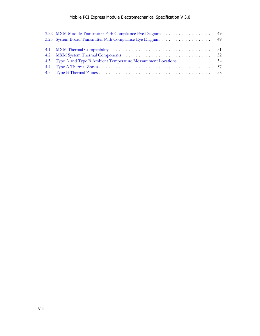
Mobile PCI Express Module Electromechanical Specification V 3.0 3.22 MXM Module Transmitter Path Compliance Eye Diagram . 3.23 System Board Transmitter Path Compliance Eye Diagram . . . . . . . . . . . 4.1 MXM Thermal Compatibility . . 4.2 MXM System Thermal Components . 4.3 Type A and Type B Ambient Temperature Measurement Locations . . 4.4 Type A Thermal Zones . 4.5 Type B Thermal Zones . . . . . . . . . . . . . . . . . . . . . . . . . . . . . . . . . . . . . . . . . . . . . . . . . . . . . . . . . . . . . . . . . . . . . . . . . . . . . . . . . . . . . . . . . . . . . . . . . . . . . . . . . . . . . . . . . . . . . . . . . . . . . . . . . . . . . . . . . . . . . . . . . . 49 49 51 52 54 57 58 viii
分享到:
收藏