Control Algorithm Modeling Guidelines
Using MATLAB®, Simulink®, and
Stateflow®
Version 5.0
MathWorks Advisory Board (MAB)
1
�
History
Date
February 2001
April 2007
July 2011
August 2012
March 2020
Trademarks
Revision
Initial document Release, Version 1.00
Version 2.00, Update release
Version 2.20, Update release
Version 3.0, Update release
Version 5.0, MAAB guidelines revised and reintroduced as
the MathWorks Advisory Board (MAB) Modeling Guidelines
MATLAB, Simulink, and Stateflow are registered trademarks of The MathWorks, Inc. See
www.mathworks.com/trademarks for a list of additional trademarks. Other product or brand names may be
trademarks or registered trademarks of their respective holders.
2
�
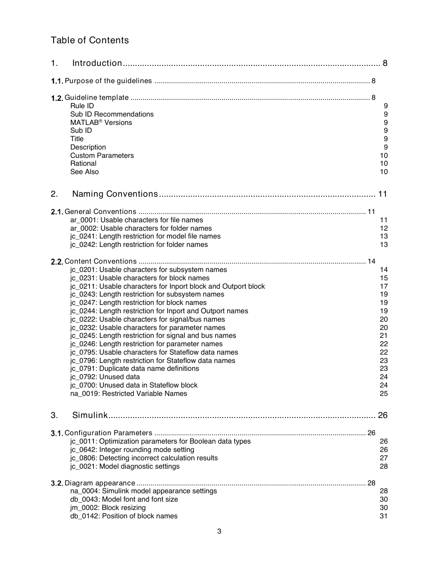
Table of Contents
1.
Introduction ........................................................................................................... 8
Purpose of the guidelines ............................................................................................................. 8
Guideline template ......................................................................................................................... 8
Rule ID
Sub ID Recommendations
MATLAB® Versions
Sub ID
Title
Description
Custom Parameters
Rational
See Also
9
9
9
9
9
9
10
10
10
2. Naming Conventions .......................................................................................... 11
General Conventions ................................................................................................................... 11
ar_0001: Usable characters for file names
ar_0002: Usable characters for folder names
jc_0241: Length restriction for model file names
jc_0242: Length restriction for folder names
Content Conventions ................................................................................................................... 14
jc_0201: Usable characters for subsystem names
jc_0231: Usable characters for block names
jc_0211: Usable characters for Inport block and Outport block
jc_0243: Length restriction for subsystem names
jc_0247: Length restriction for block names
jc_0244: Length restriction for Inport and Outport names
jc_0222: Usable characters for signal/bus names
jc_0232: Usable characters for parameter names
jc_0245: Length restriction for signal and bus names
jc_0246: Length restriction for parameter names
jc_0795: Usable characters for Stateflow data names
jc_0796: Length restriction for Stateflow data names
jc_0791: Duplicate data name definitions
jc_0792: Unused data
jc_0700: Unused data in Stateflow block
na_0019: Restricted Variable Names
11
12
13
13
14
15
17
19
19
19
20
20
21
22
22
23
23
24
24
25
3.
Simulink ............................................................................................................... 26
Configuration Parameters ........................................................................................................... 26
jc_0011: Optimization parameters for Boolean data types
jc_0642: Integer rounding mode setting
jc_0806: Detecting incorrect calculation results
jc_0021: Model diagnostic settings
Diagram appearance .................................................................................................................... 28
na_0004: Simulink model appearance settings
db_0043: Model font and font size
jm_0002: Block resizing
db_0142: Position of block names
3
26
26
27
28
28
30
30
31
�
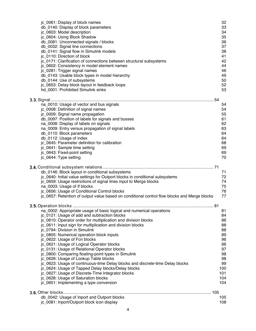
jc_0061: Display of block names
db_0140: Display of block parameters
jc_0603: Model description
jc_0604: Using Block Shadow
db_0081: Unconnected signals / blocks
db_0032: Signal line connections
db_0141: Signal flow in Simulink models
jc_0110: Direction of block
jc_0171: Clarification of connections between structural subsystems
jc_0602: Consistency in model element names
jc_0281: Trigger signal names
db_0143: Usable block types in model hierarchy
db_0144: Use of subsystems
jc_0653: Delay block layout in feedback loops
hd_0001: Prohibited Simulink sinks
Signal ............................................................................................................................................. 54
na_0010: Usage of vector and bus signals
jc_0008: Definition of signal names
jc_0009: Signal name propagation
db_0097: Position of labels for signals and busses
na_0008: Display of labels on signals
na_0009: Entry versus propagation of signal labels
db_0110: Block parameters
db_0112: Usage of index
jc_0645: Parameter definition for calibration
jc_0641: Sample time setting
jc_0643: Fixed-point setting
jc_0644: Type setting
Conditional subsystem relations ................................................................................................ 71
db_0146: Block layout in conditional subsystems
jc_0640: Initial value settings for Outport blocks in conditional subsystems
jc_0659: Usage restrictions of signal lines input to Merge blocks
na_0003: Usage of If blocks
jc_0656: Usage of Conditional Control blocks
jc_0657: Retention of output value based on conditional control flow blocks and Merge blocks
Operation blocks .......................................................................................................................... 81
32
33
34
35
36
37
38
41
42
44
46
49
50
52
53
54
54
55
61
62
63
64
64
68
69
69
70
71
72
74
75
76
77
na_0002: Appropriate usage of basic logical and numerical operations
jc_0121: Usage of add and subtraction blocks
jc_0610: Operator order for multiplication and division blocks
jc_0611: Input sign for multiplication and division blocks
jc_0794: Division in Simulink
jc_0805: Numerical operation block inputs
jc_0622: Usage of Fcn blocks
jc_0621: Usage of Logical Operator blocks
jc_0131: Usage of Relational Operator blocks
jc_0800: Comparing floating-point types in Simulink
jc_0626: Usage of Lookup Table blocks
jc_0623: Usage of continuous-time Delay blocks and discrete-time Delay blocks
jc_0624: Usage of Tapped Delay blocks/Delay blocks
jc_0627: Usage of Discrete-Time Integrator blocks
jc_0628: Usage of Saturation blocks
jc_0651: Implementing a type conversion
81
84
86
88
88
89
96
96
97
98
98
99
100
101
104
104
Other blocks ................................................................................................................................ 105
db_0042: Usage of Inport and Outport blocks
jc_0081: Inport/Outport block icon display
4
105
108
�
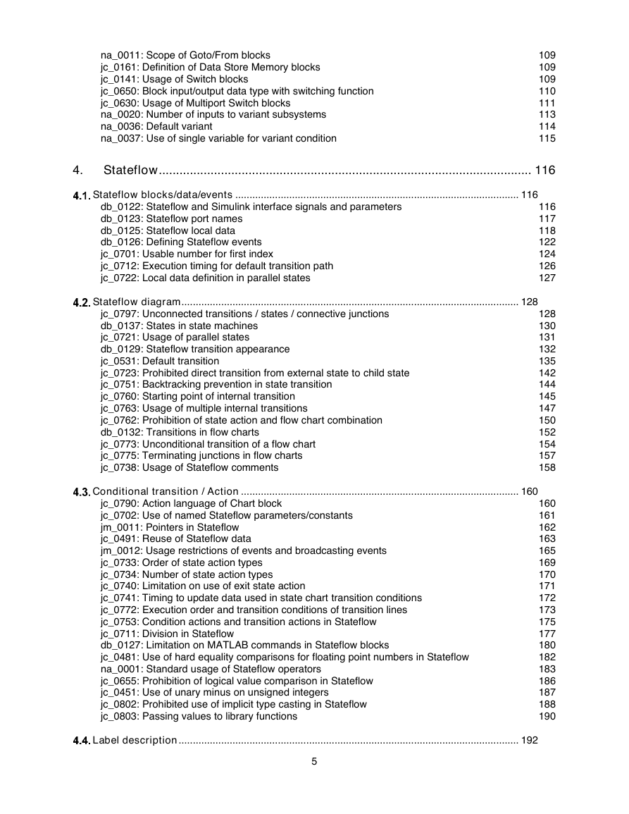
na_0011: Scope of Goto/From blocks
jc_0161: Definition of Data Store Memory blocks
jc_0141: Usage of Switch blocks
jc_0650: Block input/output data type with switching function
jc_0630: Usage of Multiport Switch blocks
na_0020: Number of inputs to variant subsystems
na_0036: Default variant
na_0037: Use of single variable for variant condition
109
109
109
110
111
113
114
115
4.
Stateflow ............................................................................................................ 116
Stateflow blocks/data/events .................................................................................................... 116
db_0122: Stateflow and Simulink interface signals and parameters
db_0123: Stateflow port names
db_0125: Stateflow local data
db_0126: Defining Stateflow events
jc_0701: Usable number for first index
jc_0712: Execution timing for default transition path
jc_0722: Local data definition in parallel states
116
117
118
122
124
126
127
Stateflow diagram ....................................................................................................................... 128
jc_0797: Unconnected transitions / states / connective junctions
db_0137: States in state machines
jc_0721: Usage of parallel states
db_0129: Stateflow transition appearance
jc_0531: Default transition
jc_0723: Prohibited direct transition from external state to child state
jc_0751: Backtracking prevention in state transition
jc_0760: Starting point of internal transition
jc_0763: Usage of multiple internal transitions
jc_0762: Prohibition of state action and flow chart combination
db_0132: Transitions in flow charts
jc_0773: Unconditional transition of a flow chart
jc_0775: Terminating junctions in flow charts
jc_0738: Usage of Stateflow comments
128
130
131
132
135
142
144
145
147
150
152
154
157
158
Conditional transition / Action .................................................................................................. 160
jc_0790: Action language of Chart block
jc_0702: Use of named Stateflow parameters/constants
jm_0011: Pointers in Stateflow
jc_0491: Reuse of Stateflow data
jm_0012: Usage restrictions of events and broadcasting events
jc_0733: Order of state action types
jc_0734: Number of state action types
jc_0740: Limitation on use of exit state action
jc_0741: Timing to update data used in state chart transition conditions
jc_0772: Execution order and transition conditions of transition lines
jc_0753: Condition actions and transition actions in Stateflow
jc_0711: Division in Stateflow
db_0127: Limitation on MATLAB commands in Stateflow blocks
jc_0481: Use of hard equality comparisons for floating point numbers in Stateflow
na_0001: Standard usage of Stateflow operators
jc_0655: Prohibition of logical value comparison in Stateflow
jc_0451: Use of unary minus on unsigned integers
jc_0802: Prohibited use of implicit type casting in Stateflow
jc_0803: Passing values to library functions
160
161
162
163
165
169
170
171
172
173
175
177
180
182
183
186
187
188
190
Label description ........................................................................................................................ 192
5
�
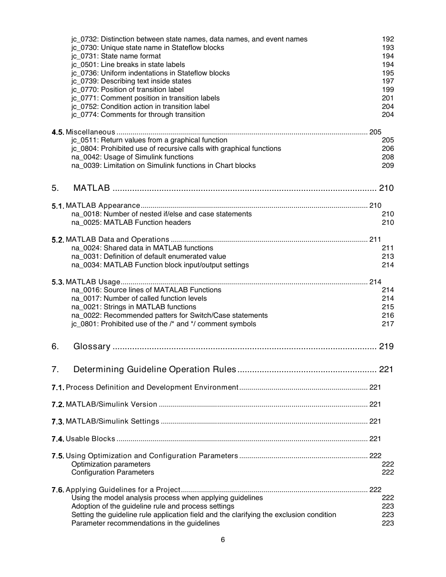
jc_0732: Distinction between state names, data names, and event names
jc_0730: Unique state name in Stateflow blocks
jc_0731: State name format
jc_0501: Line breaks in state labels
jc_0736: Uniform indentations in Stateflow blocks
jc_0739: Describing text inside states
jc_0770: Position of transition label
jc_0771: Comment position in transition labels
jc_0752: Condition action in transition label
jc_0774: Comments for through transition
192
193
194
194
195
197
199
201
204
204
Miscellaneous ............................................................................................................................. 205
jc_0511: Return values from a graphical function
jc_0804: Prohibited use of recursive calls with graphical functions
na_0042: Usage of Simulink functions
na_0039: Limitation on Simulink functions in Chart blocks
205
206
208
209
5. MATLAB ............................................................................................................ 210
MATLAB Appearance ................................................................................................................. 210
na_0018: Number of nested if/else and case statements
na_0025: MATLAB Function headers
210
210
MATLAB Data and Operations .................................................................................................. 211
na_0024: Shared data in MATLAB functions
na_0031: Definition of default enumerated value
na_0034: MATLAB Function block input/output settings
211
213
214
MATLAB Usage ........................................................................................................................... 214
na_0016: Source lines of MATALAB Functions
na_0017: Number of called function levels
na_0021: Strings in MATLAB functions
na_0022: Recommended patters for Switch/Case statements
jc_0801: Prohibited use of the /* and */ comment symbols
214
214
215
216
217
6. Glossary ............................................................................................................ 219
7. Determining Guideline Operation Rules ......................................................... 221
Process Definition and Development Environment ................................................................ 221
MATLAB/Simulink Version ........................................................................................................ 221
MATLAB/Simulink Settings ....................................................................................................... 221
Usable Blocks ............................................................................................................................. 221
Using Optimization and Configuration Parameters ................................................................ 222
Optimization parameters
Configuration Parameters
222
222
Applying Guidelines for a Project ............................................................................................. 222
Using the model analysis process when applying guidelines
Adoption of the guideline rule and process settings
Setting the guideline rule application field and the clarifying the exclusion condition
Parameter recommendations in the guidelines
222
223
223
223
6
�
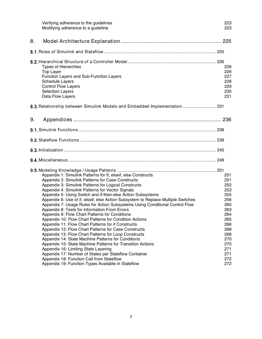
Verifying adherence to the guidelines
Modifying adherence to a guideline
223
223
8. Model Architecture Explanation ...................................................................... 225
Roles of Simulink and Stateflow ............................................................................................... 225
Hierarchical Structure of a Controller Model ........................................................................... 226
Types of Hierarchies
Top Layer
Function Layers and Sub-Function Layers
Schedule Layers
Control Flow Layers
Selection Layers
Data Flow Layers
226
226
227
228
229
230
231
Relationship between Simulink Models and Embedded Implementation ............................ 231
9. Appendices ....................................................................................................... 236
Simulink Functions .................................................................................................................... 236
Stateflow Functions ................................................................................................................... 239
Initialization ................................................................................................................................. 245
Miscellaneous ............................................................................................................................. 249
Modeling Knowledge / Usage Patterns .................................................................................... 251
Appendix 1: Simulink Patterns for If, elseif, else Constructs
Appendix 2: Simulink Patterns for Case Constructs
Appendix 3: Simulink Patterns for Logical Constructs
Appendix 4: Simulink Patterns for Vector Signals
Appendix 5: Using Switch and if-then-else Action Subsystems
Appendix 6: Use of if, elseif, else Action Subsystem to Replace Multiple Switches
Appendix 7: Usage Rules for Action Subsystems Using Conditional Control Flow
Appendix 8: Tests for Information From Errors
Appendix 9: Flow Chart Patterns for Conditions
Appendix 10: Flow Chart Patterns for Condition Actions
Appendix 11: Flow Chart Patterns for if Constructs
Appendix 12: Flow Chart Patterns for Case Constructs
Appendix 13: Flow Chart Patterns for Loop Constructs
Appendix 14: State Machine Patterns for Conditions
Appendix 15: State Machine Patterns for Transition Actions
Appendix 16: Limiting State Layering
Appendix 17: Number of States per Stateflow Container
Appendix 18: Function Call from Stateflow
Appendix 19: Function Types Available in Stateflow
251
251
252
253
255
256
260
263
264
265
266
268
268
270
270
271
271
272
272
7
�
1. Introduction
Purpose of the guidelines
MathWorks Advisory Board (MAB) guidelines stipulate important basic rules for modeling in Simulink
and Stateflow. The overall purpose of these modeling guidelines is to allow for a simple, common
understanding by modelers and consumers of control system models.
The main objectives of these guidelines are:
• Readability
Improve graphical understandability
Improve readability of functional analysis
Prevent connection mistakes
Comments, etc.
• Simulation and verification
Mechanism to enable simulation
Testability
• Code Generation
Improve the efficiency of code generation (ROM, RAM efficiency)
Ensure the robustness of generated code
Model runtime errors and recommendations that cannot be implemented are outside of the scope of
these rules.
The chapters of this document provide the following information:
Chapter 1 ― Intent of these guidelines and an overview of the guideline template.
Chapters 2 through 5 ― Guideline rules
Chapter 6 ― Glossary
Chapter 7 ― Process for evaluating and implementing guidelines for your project
Chapters 8 ― Model architecture and operations that are required for advanced users.
Chapter 9 ― Additional explanation and modelling information for Simulink/Stateflow functions, including
modeling patterns.
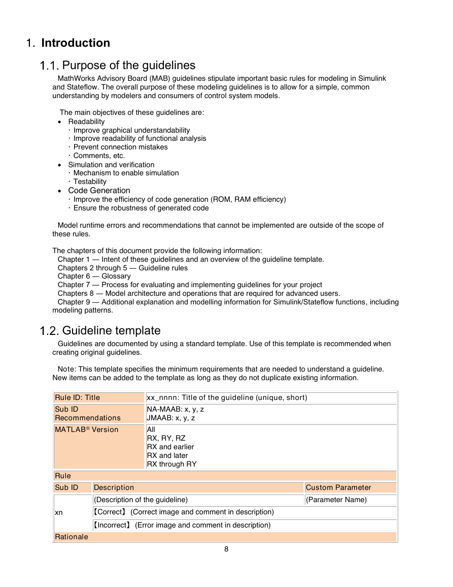
Guideline template
Guidelines are documented by using a standard template. Use of this template is recommended when
creating original guidelines.
Note: This template specifies the minimum requirements that are needed to understand a guideline.
New items can be added to the template as long as they do not duplicate existing information.
Rule ID: Title
xx_nnnn: Title of the guideline (unique, short)
Sub ID
Recommendations
MATLAB® Version
Rule
Sub ID
Description
NA-MAAB: x, y, z
JMAAB: x, y, z
All
RX, RY, RZ
RX and earlier
RX and later
RX through RY
(Description of the guideline)
xn
【Correct】 (Correct image and comment in description)
【Incorrect】 (Error image and comment in description)
Rationale
8
Custom Parameter
(Parameter Name)
�



 2023年江西萍乡中考道德与法治真题及答案.doc
 2012年重庆南川中考生物真题及答案.doc
 2013年江西师范大学地理学综合及文艺理论基础考研真题.doc
 2020年四川甘孜小升初语文真题及答案I卷.doc
 2020年注册岩土工程师专业基础考试真题及答案.doc
 2023-2024学年福建省厦门市九年级上学期数学月考试题及答案.doc
 2021-2022学年辽宁省沈阳市大东区九年级上学期语文期末试题及答案.doc
 2022-2023学年北京东城区初三第一学期物理期末试卷及答案.doc
 2018上半年江西教师资格初中地理学科知识与教学能力真题及答案.doc
 2012年河北国家公务员申论考试真题及答案-省级.doc
 2020-2021学年江苏省扬州市江都区邵樊片九年级上学期数学第一次质量检测试题及答案.doc
 2022下半年黑龙江教师资格证中学综合素质真题及答案.doc