logo资料库

IEI威强掌上无线-UPC-12A说明书.pdf

第1页 / 共144页
第2页 / 共144页
第3页 / 共144页
第4页 / 共144页
第5页 / 共144页
第6页 / 共144页
第7页 / 共144页
第8页 / 共144页
资料共144页,剩余部分请下载后查看
Revision
Copyright
Table of Contents
List of Figures
List of Tables
1 Introduction
1.1 UPC-12A/GM45 Panel PC Overview
1.1.1 Model Variations
1.1.2 Features
1.2 External Overview
1.2.1 Front Panel
1.2.2 Bottom Panel
1.2.3 Side Panels
1.2.4 Rear Panel
1.2.5 Frame
1.3 Specifications
1.3.1 Preinstalled Hardware Components
1.3.2 System Specifications
2 Detailed Specifications
2.1 Dimensions
2.2 Intel® Processor Support
2.3 Motherboard Components
2.3.1 Memory Support
2.3.1.1 Installed Memory
2.3.1.2 Additional Memory
2.3.2 Storage Capacity
2.4 External Peripheral Interface Connectors
2.4.1 Serial Port Connectors
2.4.2 LAN Connectivity
2.4.3 External USB Connectors
2.5 UPC-12A/GM45 Front Side
2.5.1 Monitor
2.5.2 Touch-Screen Module
2.5.3 OSD Buttons
2.6 Graphics
2.6.1 Intel® GM45 Integrated Graphics Engine
2.6.2 Dual-Display
2.7 Audio
2.7.1 Stereo Speakers
2.8 System Power
2.8.1 Power Mode
2.8.1.1 AT Power Mode
2.8.1.2 ATX Power Mode
2.8.2 Power Adapter
2.8.3 Power Connectors
2.8.4 Lithium Battery
2.8.5 Power Mode
2.8.6 Power On/Off
2.8.7 Buzzer Alarm
2.9 Wireless Ethernet
3 Unpacking
3.1 Unpacking
3.1.1 Packing List
4 Installation
4.1 Anti-static Precautions
4.2 Installation Precautions
4.3 Preinstalled Components
4.4 Installation and Configuration Steps
4.5 CF Card Installation
4.6 HDD Installation
4.7 Battery Installation
4.8 PCI Expansion Card Installation
4.9 Jumper Settings
4.9.1 Access the Jumpers
4.9.2 Preconfigured Jumpers
4.9.3 CF Voltage Select
4.9.4 CF Card Setup
4.9.5 COM4 Function Select Jumper
4.9.5.1 COM4 RS-422 and RS-485 Pinouts
4.9.6 Clear CMOS Button
4.10 Mounting the System
4.10.1 Wall Mounting
4.10.2 Panel Mounting
4.10.3 Arm Mounting
4.11 Bottom Panel Switch and Connectors
4.11.1 AT/ATX Mode Selection
4.11.2 LAN Connection
4.11.3 Serial Device Connection
4.11.4 USB Device Connection
4.11.5 VGA Monitor Connection
5 System Maintenance
5.1 System Maintenance Introduction
5.2 Anti-static Precautions
5.3 Turn off the Power
5.4 Replacing Components
5.4.1 Hard Disk Drive Replacement
5.4.2 CF Card Replacement
5.4.3 Wireless Module Replacement
5.4.4 SO-DIMM Module Replacement
5.4.5 Gasket Replacement
5.4.6 Motherboard Replacement
6 AMI BIOS Setup
6.1 Introduction
6.1.1 Starting Setup
6.1.2 Using Setup
6.1.3 Getting Help
6.1.4 Unable to Reboot After Configuration Changes
6.1.5 BIOS Menu Bar
6.2 Main
6.3 Advanced
6.3.1 CPU Configuration
6.3.2 IDE Configuration
6.3.2.1 IDE Master, IDE Slave
6.3.3 Super IO Configuration
6.3.4 AHCI Configuration
6.3.4.1 AHCI Port n
6.3.5 Remote Access Configuration
6.3.6 USB Configuration
6.3.7 Power Configuration
6.4 PCI/PnP
6.5 Boot
6.5.1 Boot Settings Configuration
6.6 Security
6.7 Chipset
6.7.1 Northbridge Configuration
6.7.2 Southbridge Configuration
6.8 Exit
7 Battery Monitoring and Remote Control
7.1 Introduction
7.2 Monitoring DC Power and Smart Battery
7.2.1 Application Installation
7.2.2 Status Information
7.2.2.1 DC Detection
7.2.2.2 Battery Detection
7.2.2.3 Total Battery Time
7.2.3 Battery Information
7.2.4 LAN Setting
7.2.5 Setting
7.3 Remote Control and Monitoring
A External Connector Pinouts
A.1 Introduction
A.2 RJ-45 GbE Connector
A.3 RJ-45 for MCU UART Connector
A.4 RJ-45 for MCU LAN Connector
A.5 Remote Power Button Connector
A.6 VGA Connector
B Safety Precautions
B.1 Safety Precautions
B.1.1 General Safety Precautions
B.1.2 Anti-static Precautions
B.1.3 Product Disposal
B.2 Maintenance and Cleaning Precautions
B.2.1 Maintenance and Cleaning
B.2.2 Cleaning Tools
C BIOS Configuration Options
C.1 BIOS Configuration Options
D Watchdog Timer
E Hazardous Materials Disclosure
E.1 Hazardous Material Disclosure Table for IPB Products Certified as RoHS Compliant Under 2002/95/EC Without Mercury
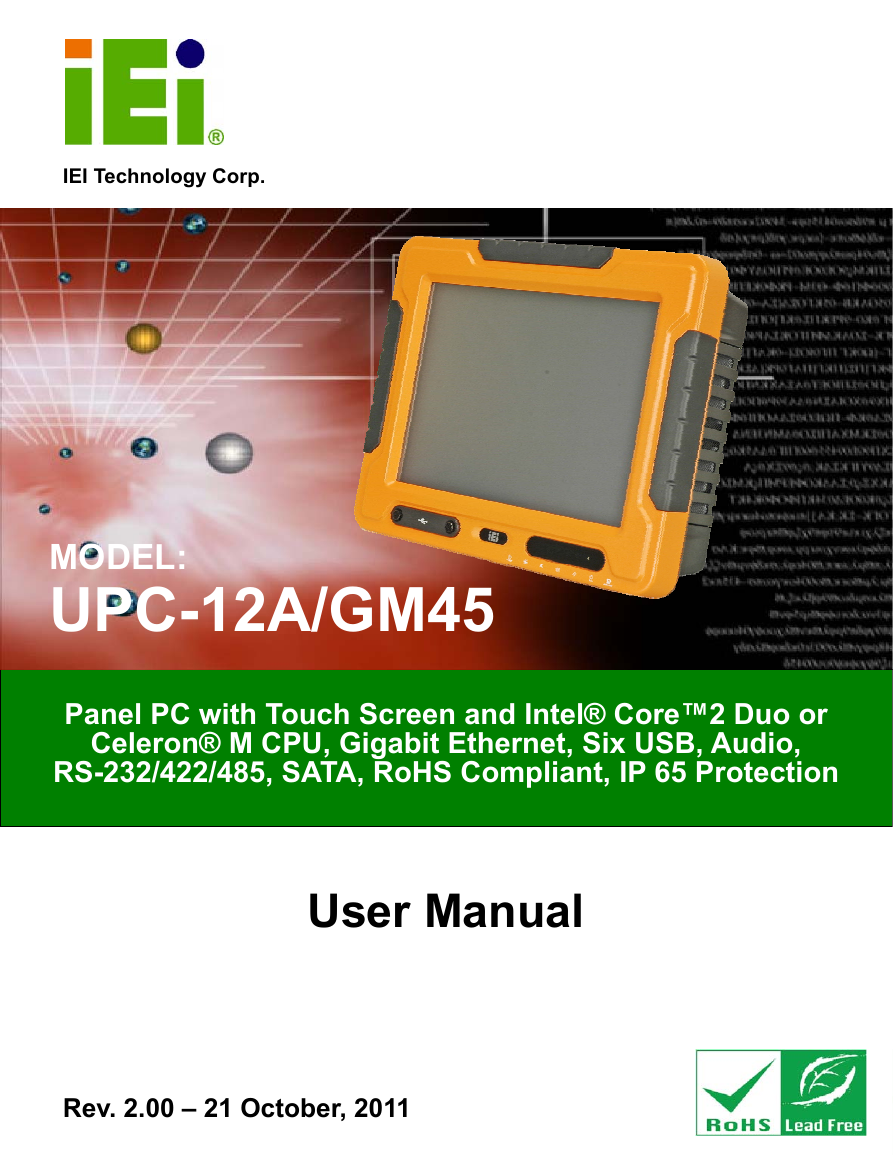
UPC-12A/GM45 Panel PC UPC-12A/GM45 Panel PC IEI Technology Corp. MODEL: UPC-12A/GM45 Panel PC with Touch Screen and Intel® Core™2 Duo or RS-232/422/485, SATA, RoHS Compliant, IP 65 Protection Celeron® M CPU, Gigabit Ethernet, Six USB, Audio, User Manual Rev. 2.00 – 21 October, 2011 Page i
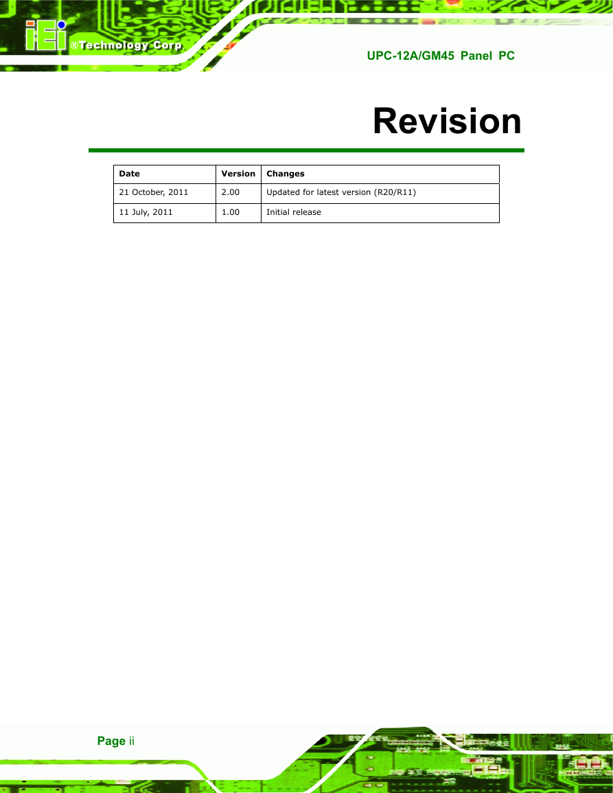
UPC-12A/GM45 Panel PC Revision Date Version Changes 21 October, 2011 11 July, 2011 2.00 1.00 Updated for latest version (R20/R11) Initial release Page ii
UPC-12A/GM45 Panel PC Copyright COPYRIGHT NOTICE The information in this document is subject to change without prior notice in order to improve reliability, design and function and does not represent a commitment on the part of the manufacturer. In no event will the manufacturer be liable for direct, indirect, special, incidental, or consequential damages arising out of the use or inability to use the product or documentation, even if advised of the possibility of such damages. This document contains proprietary information protected by copyright. All rights are reserved. No part of this manual may be reproduced by any mechanical, electronic, or other means in any form without prior written permission of the manufacturer. TRADEMARKS All registered trademarks and product names mentioned herein are used for identification purposes only and may be trademarks and/or registered trademarks of their respective owners. Page iii
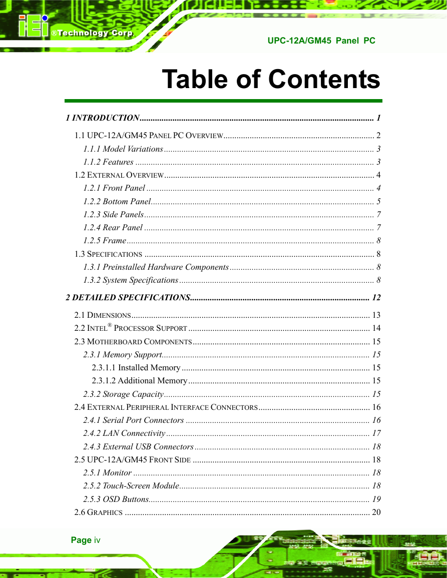
UPC-12A/GM45 Panel PC Table of Contents 01 INTRODUCTION........................................................................................................... 2 H1 H1.1 UPC-12A/GM45 PANEL PC OVERVIEW..................................................................... 2 H1.1.1 Model Variations................................................................................................ 2 H1.1.2 Features ............................................................................................................. 2 H1.2 EXTERNAL OVERVIEW................................................................................................ 2 H1.2.1 Front Panel ........................................................................................................ 2 H1.2.2 Bottom Panel...................................................................................................... 2 H1.2.3 Side Panels......................................................................................................... 2 H1.2.4 Rear Panel ......................................................................................................... 2 H1.2.5 Frame................................................................................................................. 2 H1.3 SPECIFICATIONS ......................................................................................................... 3 H1.3.1 Preinstalled Hardware Components.................................................................. 3 H1.3.2 System Specifications......................................................................................... 3 H2 DETAILED SPECIFICATIONS.................................................................................. 3 H2 H3 H3 H4 H4 H5 H7 H7 H8 H8 H8 H8 H12 H2.1 DIMENSIONS............................................................................................................. 3 H2.2 INTEL® PROCESSOR SUPPORT................................................................................... 3 H2.3 MOTHERBOARD COMPONENTS................................................................................. 3 H2.3.1 Memory Support............................................................................................... 3 H2.3.1.1 Installed Memory...................................................................................... 3 H2.3.1.2 Additional Memory................................................................................... 3 H2.3.2 Storage Capacity.............................................................................................. 3 H2.4 EXTERNAL PERIPHERAL INTERFACE CONNECTORS................................................... 3 H2.4.1 Serial Port Connectors .................................................................................... 3 H2.4.2 LAN Connectivity............................................................................................. 3 H2.4.3 External USB Connectors................................................................................ 3 H2.5 UPC-12A/GM45 FRONT SIDE ................................................................................. 3 H2.5.1 Monitor ............................................................................................................ 3 H2.5.2 Touch-Screen Module....................................................................................... 3 H2.5.3 OSD Buttons..................................................................................................... 3 H2.6 GRAPHICS ................................................................................................................ 3 H13 H14 H15 H15 H15 H15 H15 H16 H16 H17 H18 H18 H18 H18 H19 H20 Page iv 9 0 H 2 9 0 1 H 1 9 1 H 2 9 1 2 H 2 9 2 H 2 9 2 3 H 3 9 3 H 2 9 3 4 H 4 9 4 H 2 9 4 5 H 5 9 5 H 2 9 5 6 H 6 9 6 H 2 9 6 7 H 7 9 7 H 2 9 7 8 H 8 9 8 H 2 9 8 9 H 9 9 9 H 2 9 9 1 0 H 1 0 0 0 H 3 0 0 1 1 H 1 1 0 1 H 3 0 1 1 2 H 1 2 0 2 H 3 0 2 1 3 H 1 3 0 3 H 3 0 3 1 4 H 1 4 0 4 H 3 0 4 1 5 H 1 5 0 5 H 3 0 5 1 6 H 1 6 0 6 H 3 0 6 1 7 H 1 7 0 7 H 3 0 7 1 8 H 1 8 0 8 H 3 0 8 1 9 H 1 9 0 9 H 3 0 9 2 0 H 2 0 1 0 H 3 1 0 2 1 H 2 1 1 1 H 3 1 1 2 2 H 2 2 1 2 H 3 1 2 2 3 H 2 3 1 3 H 3 1 3 2 4 H 2 4 1 4 H 3 1 4 2 5 H 2 5 1 5 H 3 1 5 2 6 H 2 6 1 6 H 3 1 6 2 7 H 2 7 1 7 H 3 1 7 2 8 H 2 8 1 8 H 3 1 8 2 9 H 2 9 1 9 H 3 1 9
UPC-12A/GM45 Panel PC H2.6.1 Intel® GM45 Integrated Graphics Engine ....................................................... 3 H2.6.2 Dual-Display.................................................................................................... 3 H2.7 AUDIO ...................................................................................................................... 3 H2.7.1 Stereo Speakers ................................................................................................ 3 H2.8 SYSTEM POWER ....................................................................................................... 3 H2.8.1 Power Mode..................................................................................................... 3 H2.8.1.1 AT Power Mode ........................................................................................ 3 H2.8.1.2 ATX Power Mode ..................................................................................... 3 H2.8.2 Power Adapter ................................................................................................. 3 H2.8.3 Power Connectors............................................................................................ 3 H2.8.4 Lithium Battery ................................................................................................ 3 H2.8.5 Power Mode..................................................................................................... 3 H2.8.6 Power On/Off ................................................................................................... 3 H2.8.7 Buzzer Alarm.................................................................................................... 3 H2.9 WIRELESS ETHERNET............................................................................................... 3 H3 UNPACKING ................................................................................................................ 3 H20 H20 H20 H21 H21 H21 H21 H21 H21 H21 H22 H23 H24 H26 H26 H27 H3.1 UNPACKING.............................................................................................................. 3 H3.1.1 Packing List ..................................................................................................... 3 H4 INSTALLATION........................................................................................................... 3 H28 H29 H31 H4.1 ANTI-STATIC PRECAUTIONS...................................................................................... 3 H4.2 INSTALLATION PRECAUTIONS................................................................................... 3 H4.3 PREINSTALLED COMPONENTS................................................................................... 3 H4.4 INSTALLATION AND CONFIGURATION STEPS ............................................................. 3 H4.5 CF CARD INSTALLATION .......................................................................................... 3 H4.6 HDD INSTALLATION................................................................................................. 3 H4.7 BATTERY INSTALLATION........................................................................................... 3 H4.8 PCI EXPANSION CARD INSTALLATION...................................................................... 3 H4.9 JUMPER SETTINGS .................................................................................................... 3 H4.9.1 Access the Jumpers .......................................................................................... 3 H4.9.2 Preconfigured Jumpers .................................................................................... 3 H4.9.3 CF Voltage Select............................................................................................. 3 H4.9.4 CF Card Setup ................................................................................................. 3 H4.9.5 COM4 Function Select Jumper........................................................................ 3 H32 H32 H33 H33 H34 H34 H37 H38 H39 H40 H40 H40 H41 H42 Page v 3 0 H 3 0 2 0 H 3 2 0 3 1 H 3 1 2 1 H 3 2 1 3 2 H 3 2 2 2 H 3 2 2 3 3 H 3 3 2 3 H 3 2 3 3 4 H 3 4 2 4 H 3 2 4 3 5 H 3 5 2 5 H 3 2 5 3 6 H 3 6 2 6 H 3 2 6 3 7 H 3 7 2 7 H 3 2 7 3 8 H 3 8 2 8 H 3 2 8 3 9 H 3 9 2 9 H 3 2 9 4 0 H 4 0 3 0 H 3 3 0 4 1 H 4 1 3 1 H 3 3 1 4 2 H 4 2 3 2 H 3 3 2 4 3 H 4 3 3 3 H 3 3 3 4 4 H 4 4 3 4 H 3 3 4 4 5 H 4 5 3 5 H 3 3 5 4 6 H 4 6 3 6 H 3 3 6 4 7 H 4 7 3 7 H 3 3 7 4 8 H 4 8 3 8 H 3 3 8 4 9 H 4 9 3 9 H 3 3 9 5 0 H 5 0 4 0 H 3 4 0 5 1 H 5 1 4 1 H 3 4 1 5 2 H 5 2 4 2 H 3 4 2 5 3 H 5 3 4 3 H 3 4 3 5 4 H 5 4 4 4 H 3 4 4 5 5 H 5 5 4 5 H 3 4 5 5 6 H 5 6 4 6 H 3 4 6 5 7 H 5 7 4 7 H 3 4 7 5 8 H 5 8 4 8 H 3 4 8 5 9 H 5 9 4 9 H 3 4 9 6 0 H 6 0 5 0 H 3 5 0 6 1 H 6 1 5 1 H 3 5 1 6 2 H 6 2 5 2 H 3 5 2
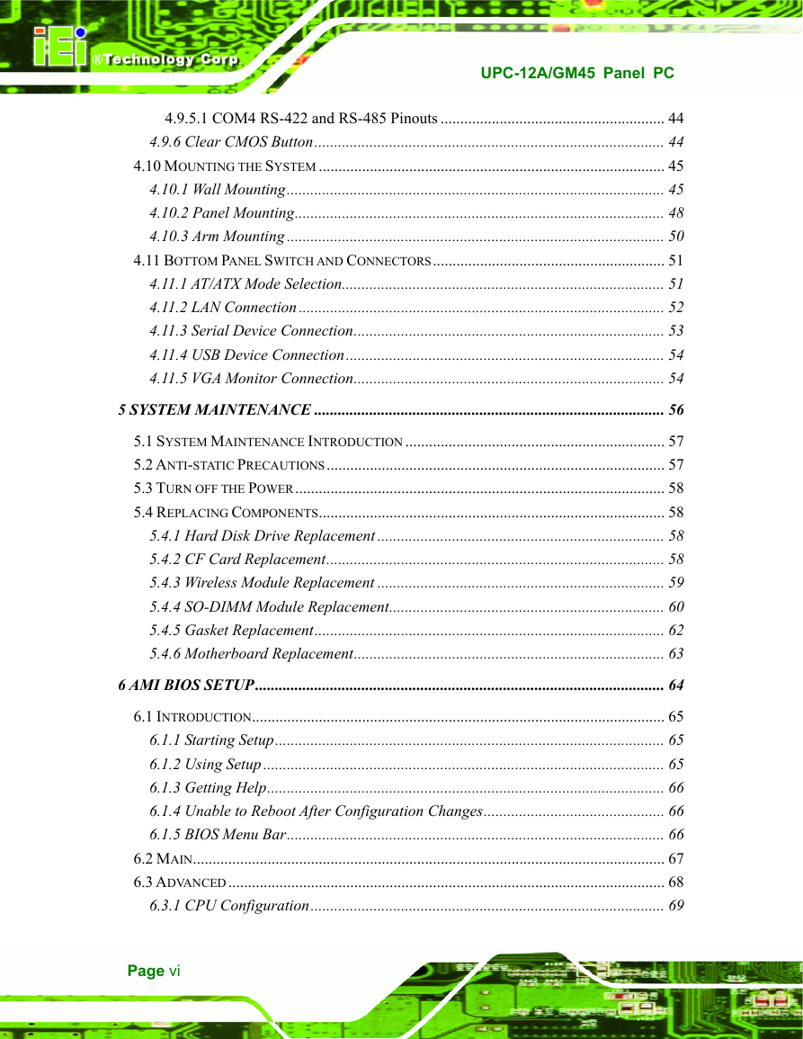
UPC-12A/GM45 Panel PC H4.9.5.1 COM4 RS-422 and RS-485 Pinouts ......................................................... 3 H4.9.6 Clear CMOS Button......................................................................................... 3 H4.10 MOUNTING THE SYSTEM ........................................................................................ 3 H4.10.1 Wall Mounting................................................................................................ 3 H4.10.2 Panel Mounting.............................................................................................. 3 H4.10.3 Arm Mounting ................................................................................................ 3 H4.11 BOTTOM PANEL SWITCH AND CONNECTORS........................................................... 3 H4.11.1 AT/ATX Mode Selection.................................................................................. 3 H4.11.2 LAN Connection ............................................................................................. 3 H4.11.3 Serial Device Connection............................................................................... 3 H4.11.4 USB Device Connection................................................................................. 3 H4.11.5 VGA Monitor Connection............................................................................... 3 H5 SYSTEM MAINTENANCE ......................................................................................... 3 H44 H44 H45 H45 H48 H50 H51 H51 H52 H53 H54 H54 H56 H5.1 SYSTEM MAINTENANCE INTRODUCTION .................................................................. 3 H5.2 ANTI-STATIC PRECAUTIONS...................................................................................... 3 H5.3 TURN OFF THE POWER.............................................................................................. 3 H5.4 REPLACING COMPONENTS........................................................................................ 3 H5.4.1 Hard Disk Drive Replacement ......................................................................... 3 H5.4.2 CF Card Replacement...................................................................................... 3 H5.4.3 Wireless Module Replacement ......................................................................... 3 H5.4.4 SO-DIMM Module Replacement...................................................................... 3 H5.4.5 Gasket Replacement......................................................................................... 3 H5.4.6 Motherboard Replacement............................................................................... 3 H6 AMI BIOS SETUP........................................................................................................ 3 H57 H57 H58 H58 H58 H58 H59 H60 H62 H63 H64 H6.1 INTRODUCTION......................................................................................................... 3 H6.1.1 Starting Setup................................................................................................... 3 H6.1.2 Using Setup ...................................................................................................... 3 H6.1.3 Getting Help..................................................................................................... 3 H6.1.4 Unable to Reboot After Configuration Changes.............................................. 3 H6.1.5 BIOS Menu Bar................................................................................................ 3 H6.2 MAIN........................................................................................................................ 3 H6.3 ADVANCED............................................................................................................... 3 H6.3.1 CPU Configuration.......................................................................................... 3 H65 H65 H65 H66 H66 H66 H67 H68 H69 Page vi 6 3 H 6 3 5 3 H 3 5 3 6 4 H 6 4 5 4 H 3 5 4 6 5 H 6 5 5 5 H 3 5 5 6 6 H 6 6 5 6 H 3 5 6 6 7 H 6 7 5 7 H 3 5 7 6 8 H 6 8 5 8 H 3 5 8 6 9 H 6 9 5 9 H 3 5 9 7 0 H 7 0 6 0 H 3 6 0 7 1 H 7 1 6 1 H 3 6 1 7 2 H 7 2 6 2 H 3 6 2 7 3 H 7 3 6 3 H 3 6 3 7 4 H 7 4 6 4 H 3 6 4 7 5 H 7 5 6 5 H 3 6 5 7 6 H 7 6 6 6 H 3 6 6 7 7 H 7 7 6 7 H 3 6 7 7 8 H 7 8 6 8 H 3 6 8 7 9 H 7 9 6 9 H 3 6 9 8 0 H 8 0 7 0 H 3 7 0 8 1 H 8 1 7 1 H 3 7 1 8 2 H 8 2 7 2 H 3 7 2 8 3 H 8 3 7 3 H 3 7 3 8 4 H 8 4 7 4 H 3 7 4 8 5 H 8 5 7 5 H 3 7 5 8 6 H 8 6 7 6 H 3 7 6 8 7 H 8 7 7 7 H 3 7 7 8 8 H 8 8 7 8 H 3 7 8 8 9 H 8 9 7 9 H 3 7 9 9 0 H 9 0 8 0 H 3 8 0 9 1 H 9 1 8 1 H 3 8 1 9 2 H 9 2 8 2 H 3 8 2 9 3 H 9 3 8 3 H 3 8 3 9 4 H 9 4 8 4 H 3 8 4 9 5 H 9 5 8 5 H 3 8 5
UPC-12A/GM45 Panel PC H6.3.2 IDE Configuration ........................................................................................... 3 H6.3.2.1 IDE Master, IDE Slave ............................................................................. 3 H6.3.3 Super IO Configuration ................................................................................... 3 H6.3.4 AHCI Configuration......................................................................................... 3 H6.3.4.1 AHCI Port n .............................................................................................. 3 H6.3.5 Remote Access Configuration .......................................................................... 3 H6.3.6 USB Configuration........................................................................................... 3 H6.3.7 Power Configuration ....................................................................................... 3 H6.4 PCI/PNP................................................................................................................... 3 H6.5 BOOT........................................................................................................................ 3 H6.5.1 Boot Settings Configuration............................................................................. 3 H6.6 SECURITY................................................................................................................. 3 H6.7 CHIPSET ................................................................................................................... 3 H6.7.1 Northbridge Configuration .............................................................................. 3 H6.7.2 Southbridge Configuration .............................................................................. 4 H6.8 EXIT ......................................................................................................................... 4 H7 BATTERY MONITORING AND REMOTE CONTROL............................................ 4 H69 H71 H77 H79 H80 H81 H84 H86 H86 H89 H89 H91 H92 H93 H95 H97 H99 H7.1 INTRODUCTION....................................................................................................... 4 H7.2 MONITORING DC POWER AND SMART BATTERY .................................................... 4 H7.2.1 Application Installation.................................................................................. 4 H7.2.2 Status Information.......................................................................................... 4 H7.2.2.1 DC Detection .......................................................................................... 4 H7.2.2.2 Battery Detection .................................................................................... 4 H7.2.2.3 Total Battery Time .................................................................................. 4 H7.2.3 Battery Information........................................................................................ 4 H7.2.4 LAN Setting .................................................................................................... 4 H7.2.5 Setting ............................................................................................................ 4 H7.3 REMOTE CONTROL AND MONITORING.................................................................... 4 HA EXTERNAL CONNECTOR PINOUTS ..................................................................... 4 H100 H100 H100 H103 H103 H104 H104 H105 H105 H107 H109 H114 HA.1 INTRODUCTION....................................................................................................... 4 HA.2 RJ-45 GBE CONNECTOR ........................................................................................ 4 HA.3 RJ-45 FOR MCU UART CONNECTOR .................................................................... 4 HA.4 RJ-45 FOR MCU LAN CONNECTOR....................................................................... 4 H115 H115 H115 H116 Page vii 9 6 H 9 6 8 6 H 3 8 6 9 7 H 9 7 8 7 H 3 8 7 9 8 H 9 8 8 8 H 3 8 8 9 9 H 9 9 8 9 H 3 8 9 1 0 0 H 1 0 0 9 0 H 3 9 0 1 0 1 H 1 0 1 9 1 H 3 9 1 1 0 2 H 1 0 2 9 2 H 3 9 2 1 0 3 H 1 0 3 9 3 H 3 9 3 1 0 4 H 1 0 4 9 4 H 3 9 4 1 0 5 H 1 0 5 9 5 H 3 9 5 1 0 6 H 1 0 6 9 6 H 3 9 6 1 0 7 H 1 0 7 9 7 H 3 9 7 1 0 8 H 1 0 8 9 8 H 3 9 8 1 0 9 H 1 0 9 9 9 H 3 9 9 1 1 0 H 1 1 0 0 0 H 4 0 0 1 1 1 H 1 1 1 0 1 H 4 0 1 1 1 2 H 1 1 2 0 2 H 4 0 2 1 1 3 H 1 1 3 0 3 H 4 0 3 1 1 4 H 1 1 4 0 4 H 4 0 4 1 1 5 H 1 1 5 0 5 H 4 0 5 1 1 6 H 1 1 6 0 6 H 4 0 6 1 1 7 H 1 1 7 0 7 H 4 0 7 1 1 8 H 1 1 8 0 8 H 4 0 8 1 1 9 H 1 1 9 0 9 H 4 0 9 1 2 0 H 1 2 0 1 0 H 4 1 0 1 2 1 H 1 2 1 1 1 H 4 1 1 1 2 2 H 1 2 2 1 2 H 4 1 2 1 2 3 H 1 2 3 1 3 H 4 1 3 1 2 4 H 1 2 4 1 4 H 4 1 4 1 2 5 H 1 2 5 1 5 H 4 1 5 1 2 6 H 1 2 6 1 6 H 4 1 6 1 2 7 H 1 2 7 1 7 H 4 1 7 1 2 8 H 1 2 8 1 8 H 4 1 8
UPC-12A/GM45 Panel PC HA.5 REMOTE POWER BUTTON CONNECTOR .................................................................. 4 HA.6 VGA CONNECTOR.................................................................................................. 4 HB SAFETY PRECAUTIONS.......................................................................................... 4 H116 H117 H118 HB.1 SAFETY PRECAUTIONS............................................................................................ 4 HB.1.1 General Safety Precautions............................................................................ 4 HB.1.2 Anti-static Precautions .................................................................................. 4 HB.1.3 Product Disposal ........................................................................................... 4 HB.2 MAINTENANCE AND CLEANING PRECAUTIONS ...................................................... 4 HB.2.1 Maintenance and Cleaning............................................................................ 4 HB.2.2 Cleaning Tools............................................................................................... 4 HC BIOS CONFIGURATION OPTIONS....................................................................... 4 H119 H119 H120 H121 H121 H121 H122 H123 HC.1 BIOS CONFIGURATION OPTIONS ........................................................................... 4 HD WATCHDOG TIMER ................................................................................................ 4 HE HAZARDOUS MATERIALS DISCLOSURE........................................................... 4 H124 H126 H129 HE.1 HAZARDOUS MATERIAL DISCLOSURE TABLE FOR IPB PRODUCTS CERTIFIED AS ROHS COMPLIANT UNDER 2002/95/EC WITHOUT MERCURY ..................................... 4 H130 Page viii 1 2 9 H 1 2 9 1 9 H 4 1 9 1 3 0 H 1 3 0 2 0 H 4 2 0 1 3 1 H 1 3 1 2 1 H 4 2 1 1 3 2 H 1 3 2 2 2 H 4 2 2 1 3 3 H 1 3 3 2 3 H 4 2 3 1 3 4 H 1 3 4 2 4 H 4 2 4 1 3 5 H 1 3 5 2 5 H 4 2 5 1 3 6 H 1 3 6 2 6 H 4 2 6 1 3 7 H 1 3 7 2 7 H 4 2 7 1 3 8 H 1 3 8 2 8 H 4 2 8 1 3 9 H 1 3 9 2 9 H 4 2 9 1 4 0 H 1 4 0 3 0 H 4 3 0 1 4 1 H 1 4 1 3 1 H 4 3 1 1 4 2 H 1 4 2 3 2 H 4 3 2 1 4 3 H 1 4 3 3 3 H 4 3 3
分享到:
收藏