logo资料库

IEI威强掌上无线-IKARPC-W08A-MeeGo说明书.pdf

第1页 / 共99页
第2页 / 共99页
第3页 / 共99页
第4页 / 共99页
第5页 / 共99页
第6页 / 共99页
第7页 / 共99页
第8页 / 共99页
资料共99页,剩余部分请下载后查看
Revision
Copyright
Table of Contents
List of Figures
List of Tables
BIOS Menus
1 Introduction
1.1 Overview
1.2 Features
1.3 Front Panel
1.3.1 LED Indicators
1.4 Rear Panel
1.5 Right Panel
1.6 Left Panel
1.7 Bottom Panel
1.8 Internal Overview
1.9 System Specifications
1.10 Dimensions
2 Unpacking
3 Installation
3.1 Anti-static Precautions
3.2 Installation Precautions
3.3 Installation and Configuration Steps
3.4 SIM Card Installation (Optional)
3.5 Mounting the System
3.6 Bottom Panel Connectors
3.6.1 LAN Connection
3.6.2 OBD-II Connector
3.6.3 Power Input Connection
3.6.4 Serial Device Connection
3.6.4.1 COM1 Pinouts
3.6.5 USB Device Connection
3.7 Power-On Procedure
3.7.1 Installation Checklist
3.7.2 Power-on Procedure
3.7.3 Power State
3.8 Remote Control
3.9 System Maintenance
4 SDK and Driver
4.1 IKARPC SDK
4.1.1 Camera Demo
4.1.1.1 Qt Environment Setup
4.1.1.2 Use VLC API (playFile) to Enable Camera
4.1.1.3 Camera Demo Application
4.1.2 Hotkey Demo
4.1.2.1 Qt Environment Setup
4.1.2.2 libsmbus.so.1.0.0 API
4.1.2.3 Hotkey Demo Application
4.1.3 OBD Demo
4.2 IKARPC Driver
4.3 Enable Network Connectivity
4.3.1 Enable 3G Connection
4.3.2 Enable Wi-Fi Connection
4.3.3 Enable Bluetooth Connection
4.4 Customize MeeGo Menu
4.4.1 Customize Taskbar Style
4.4.2 Add/Customize Taskbar Application Icon
4.5 Tool - Win32DiskImager
4.5.1 How to Use
5 BIOS
5.1 Introduction
5.1.1 Starting Setup
5.1.2 Using Setup
5.1.3 Getting Help
5.1.4 BIOS Menu Bar
5.2 Main
5.3 Advanced
5.3.1 CPU Configuration
5.3.2 IDE Configuration
5.3.2.1 IDE Master, IDE Slave
5.3.3 Super IO Configuration
5.3.4 Hardware Health Configuration
5.3.5 Remote Access Configuration
5.3.6 USB Configuration
5.4 PCI/PnP
5.5 Boot
5.5.1 Boot Settings Configuration
5.5.2 Boot Device Priority
5.5.3 Hard Disk Drives
5.6 Security
5.7 Chipset
5.7.1 Northbridge Configuration
5.7.2 Southbridge Configuration
5.8 Exit
A OBD-II Reader Command
A.1 Select a Chip Initial Mode: UpDate F/W or RUN F/W
A.2 Boot Mode
A.3 Run Mode
A.4 Into CAN_Standard V2.2.B (CAN standard)
A.5 Into Telematics (Vehicel Information)
B Watchdog Timer
C Hazardous Materials Disclosure
C.1 Hazardous Materials Disclosure Table for IPB Products Certified as RoHS Compliant Under 2002/95/EC Without Mercury
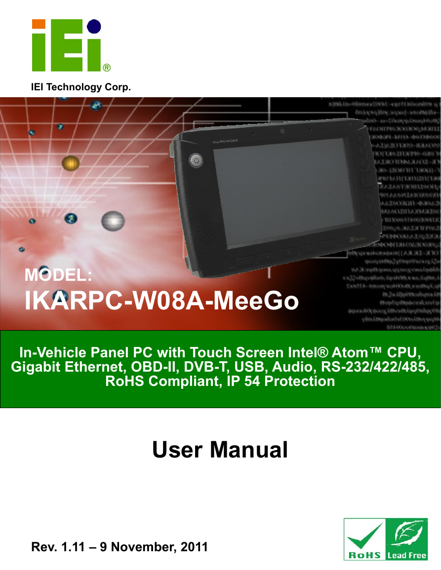
IKARPC-W08A-MeeGo In-Vehicle Panel PC IEI Technology Corp. MODEL: IKARPC-W08A-MeeGo In-Vehicle Panel PC with Touch Screen Intel® Atom™ CPU, Gigabit Ethernet, OBD-II, DVB-T, USB, Audio, RS-232/422/485, RoHS Compliant, IP 54 Protection User Manual Rev. 1.11 – 9 November, 2011 Page i
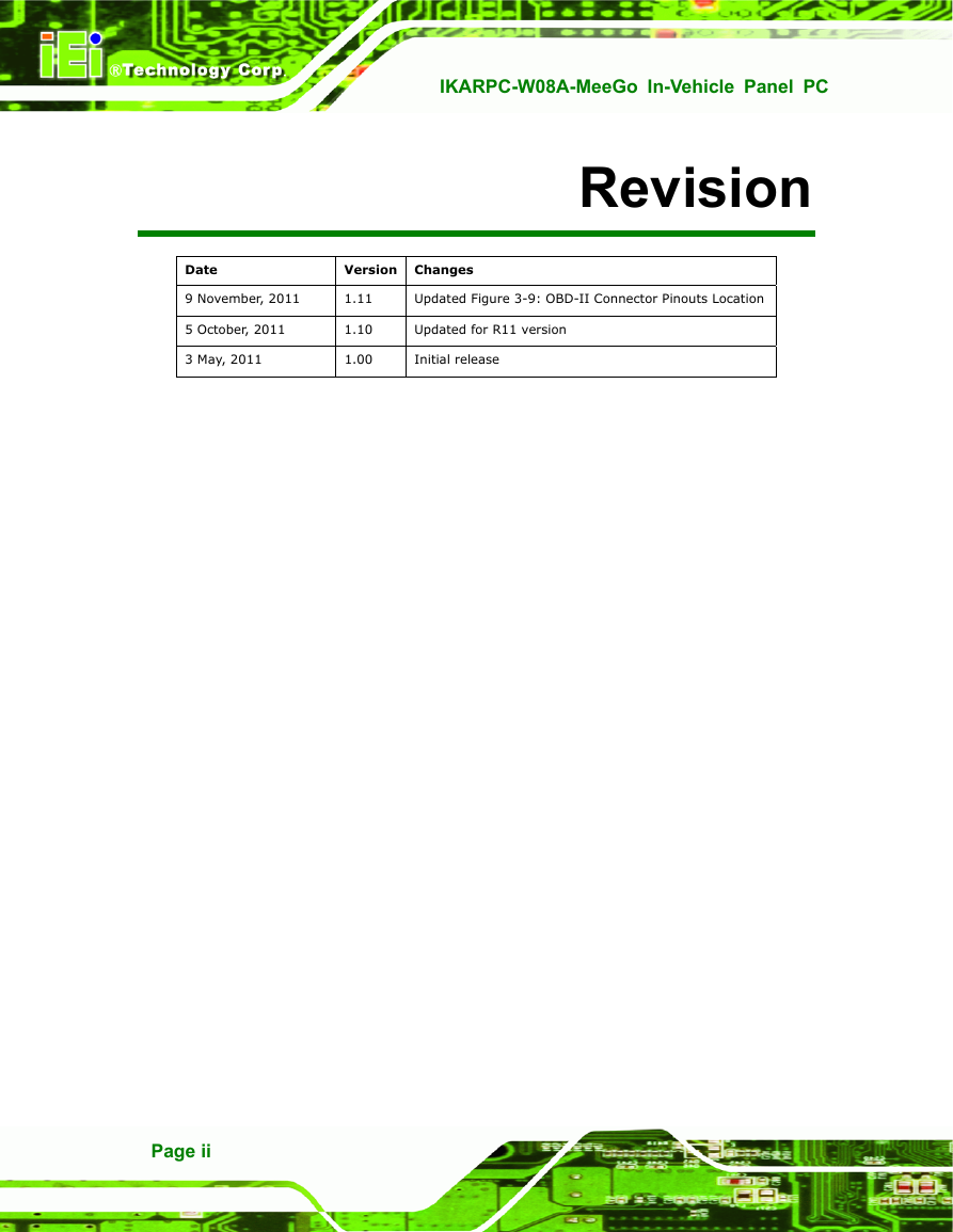
IKARPC-W08A-MeeGo In-Vehicle Panel PC Revision Date Version Changes 9 November, 2011 5 October, 2011 3 May, 2011 1.11 1.10 1.00 Updated Figure 3-9: OBD-II Connector Pinouts Location Updated for R11 version Initial release Page ii
IKARPC-W08A-MeeGo In-Vehicle Panel PC Copyright COPYRIGHT NOTICE The information in this document is subject to change without prior notice in order to improve reliability, design and function and does not represent a commitment on the part of the manufacturer. In no event will the manufacturer be liable for direct, indirect, special, incidental, or consequential damages arising out of the use or inability to use the product or documentation, even if advised of the possibility of such damages. This document contains proprietary information protected by copyright. All rights are reserved. No part of this manual may be reproduced by any mechanical, electronic, or other means in any form without prior written permission of the manufacturer. TRADEMARKS All registered trademarks and product names mentioned herein are used for identification purposes only and may be trademarks and/or registered trademarks of their respective owners. Page iii
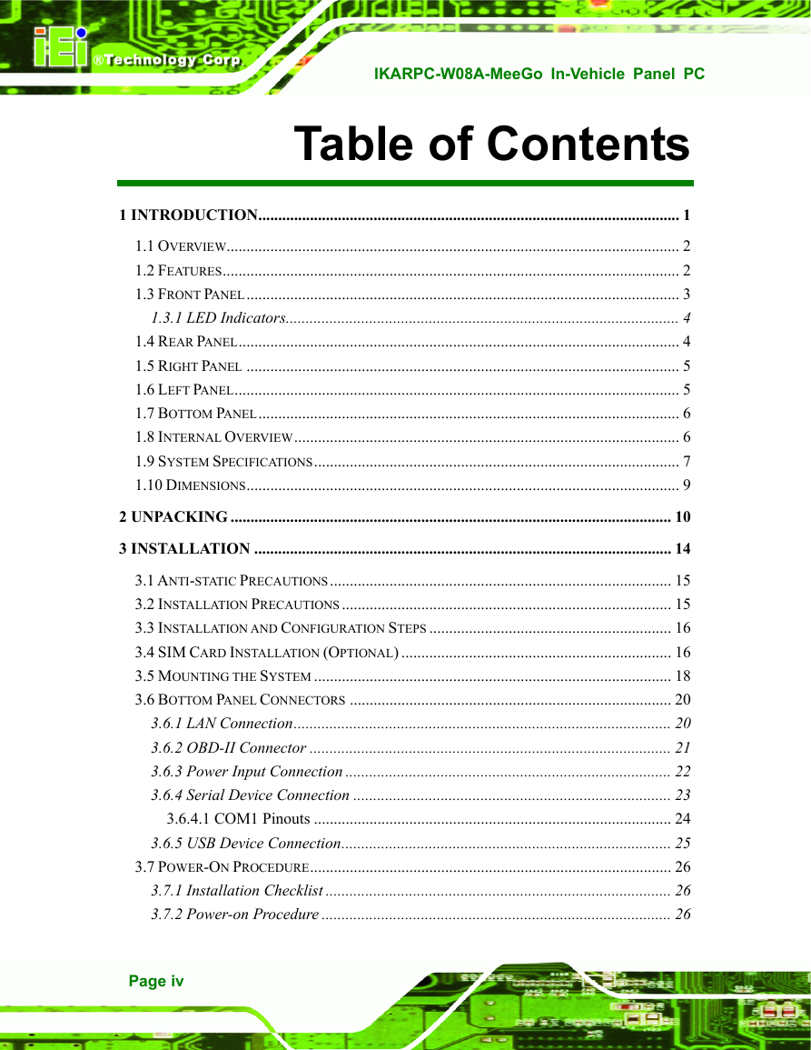
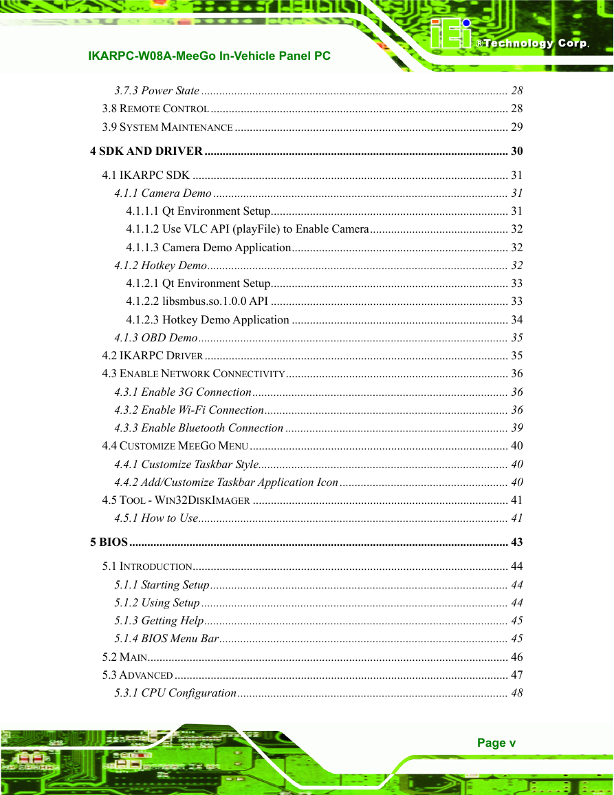
IKARPC-W08A-MeeGo In-Vehicle Panel PC Table of Contents 1 INTRODUCTION.......................................................................................................... 1 1.1 OVERVIEW.................................................................................................................. 2 1.2 FEATURES................................................................................................................... 2 1.3 FRONT PANEL............................................................................................................. 3 1.3.1 LED Indicators................................................................................................... 4 1.4 REAR PANEL............................................................................................................... 4 1.5 RIGHT PANEL ............................................................................................................. 5 1.6 LEFT PANEL................................................................................................................ 5 1.7 BOTTOM PANEL.......................................................................................................... 6 1.8 INTERNAL OVERVIEW................................................................................................. 6 1.9 SYSTEM SPECIFICATIONS............................................................................................ 7 1.10 DIMENSIONS............................................................................................................. 9 2 UNPACKING ............................................................................................................... 10 3 INSTALLATION ......................................................................................................... 14 3.1 ANTI-STATIC PRECAUTIONS...................................................................................... 15 3.2 INSTALLATION PRECAUTIONS................................................................................... 15 3.3 INSTALLATION AND CONFIGURATION STEPS ............................................................. 16 3.4 SIM CARD INSTALLATION (OPTIONAL) .................................................................... 16 3.5 MOUNTING THE SYSTEM .......................................................................................... 18 3.6 BOTTOM PANEL CONNECTORS ................................................................................. 20 3.6.1 LAN Connection............................................................................................... 20 3.6.2 OBD-II Connector ........................................................................................... 21 3.6.3 Power Input Connection .................................................................................. 22 3.6.4 Serial Device Connection ................................................................................ 23 3.6.4.1 COM1 Pinouts .......................................................................................... 24 3.6.5 USB Device Connection................................................................................... 25 3.7 POWER-ON PROCEDURE........................................................................................... 26 3.7.1 Installation Checklist ....................................................................................... 26 3.7.2 Power-on Procedure ........................................................................................ 26 Page iv
IKARPC-W08A-MeeGo In-Vehicle Panel PC 3.7.3 Power State ...................................................................................................... 28 3.8 REMOTE CONTROL................................................................................................... 28 3.9 SYSTEM MAINTENANCE ........................................................................................... 29 4 SDK AND DRIVER ..................................................................................................... 30 4.1 IKARPC SDK ......................................................................................................... 31 4.1.1 Camera Demo .................................................................................................. 31 4.1.1.1 Qt Environment Setup............................................................................... 31 4.1.1.2 Use VLC API (playFile) to Enable Camera.............................................. 32 4.1.1.3 Camera Demo Application........................................................................ 32 4.1.2 Hotkey Demo.................................................................................................... 32 4.1.2.1 Qt Environment Setup............................................................................... 33 4.1.2.2 libsmbus.so.1.0.0 API ............................................................................... 33 4.1.2.3 Hotkey Demo Application ........................................................................ 34 4.1.3 OBD Demo....................................................................................................... 35 4.2 IKARPC DRIVER..................................................................................................... 35 4.3 ENABLE NETWORK CONNECTIVITY.......................................................................... 36 4.3.1 Enable 3G Connection..................................................................................... 36 4.3.2 Enable Wi-Fi Connection................................................................................. 36 4.3.3 Enable Bluetooth Connection .......................................................................... 39 4.4 CUSTOMIZE MEEGO MENU...................................................................................... 40 4.4.1 Customize Taskbar Style................................................................................... 40 4.4.2 Add/Customize Taskbar Application Icon........................................................ 40 4.5 TOOL - WIN32DISKIMAGER ..................................................................................... 41 4.5.1 How to Use....................................................................................................... 41 5 BIOS.............................................................................................................................. 43 5.1 INTRODUCTION......................................................................................................... 44 5.1.1 Starting Setup................................................................................................... 44 5.1.2 Using Setup ...................................................................................................... 44 5.1.3 Getting Help..................................................................................................... 45 5.1.4 BIOS Menu Bar................................................................................................ 45 5.2 MAIN........................................................................................................................ 46 5.3 ADVANCED............................................................................................................... 47 5.3.1 CPU Configuration.......................................................................................... 48 Page v
IKARPC-W08A-MeeGo In-Vehicle Panel PC 5.3.2 IDE Configuration ........................................................................................... 49 5.3.2.1 IDE Master, IDE Slave ............................................................................. 50 5.3.3 Super IO Configuration ................................................................................... 55 5.3.4 Hardware Health Configuration...................................................................... 56 5.3.5 Remote Access Configuration .......................................................................... 57 5.3.6 USB Configuration........................................................................................... 59 5.4 PCI/PNP................................................................................................................... 61 5.5 BOOT........................................................................................................................ 63 5.5.1 Boot Settings Configuration............................................................................. 64 5.5.2 Boot Device Priority ........................................................................................ 66 5.5.3 Hard Disk Drives ............................................................................................. 67 5.6 SECURITY................................................................................................................. 67 5.7 CHIPSET ................................................................................................................... 68 5.7.1 Northbridge Configuration .............................................................................. 69 5.7.2 Southbridge Configuration .............................................................................. 70 5.8 EXIT ......................................................................................................................... 72 A OBD-II READER COMMAND................................................................................. 74 A.1 SELECT A CHIP INITIAL MODE: UPDATE F/W OR RUN F/W.................................... 75 A.2 BOOT MODE............................................................................................................ 75 A.3 RUN MODE.............................................................................................................. 75 A.4 INTO CAN_STANDARD V2.2.B (CAN STANDARD) ................................................. 77 A.5 INTO TELEMATICS (VEHICEL INFORMATION) ........................................................... 79 B WATCHDOG TIMER................................................................................................. 83 C HAZARDOUS MATERIALS DISCLOSURE ......................................................... 86 C.1 HAZARDOUS MATERIALS DISCLOSURE TABLE FOR IPB PRODUCTS CERTIFIED AS ROHS COMPLIANT UNDER 2002/95/EC WITHOUT MERCURY ....................................... 87 Page vi
IKARPC-W08A-MeeGo In-Vehicle Panel PC List of Figures Figure 1-1: IKARPC-W08A-MeeGo Panel PC ...............................................................................2 Figure 1-2: Front View....................................................................................................................4 Figure 1-3: LED Indicators.............................................................................................................4 Figure 1-4: Rear View .....................................................................................................................5 Figure 1-5: Right Panel ..................................................................................................................5 Figure 1-6: Left Panel .....................................................................................................................5 Figure 1-7: Bottom Panel ...............................................................................................................6 Figure 1-8: Dimensions (unit: mm) ...............................................................................................9 Figure 3-1: Back Cover Retention Screws .................................................................................16 Figure 3-2: DVB-T Module Retention Screws ............................................................................17 Figure 3-3: Open the SIM Card Slot Cover.................................................................................17 Figure 3-4: Lock the SIM Card Slot Cover..................................................................................18 Figure 3-5: Secure the Mounting Kit...........................................................................................19 Figure 3-6: Attach the Suction Cups ..........................................................................................19 Figure 3-7: LAN Connection ........................................................................................................20 Figure 3-8: OBD-II Cable and J1939/FMS Cable ........................................................................21 Figure 3-9: OBD-II Connector Pinouts Location........................................................................21 Figure 3-10: OBD-II Connector Pinouts......................................................................................22 Figure 3-11: J1939/FMS Connector Pinouts ..............................................................................22 Figure 3-12: Power Input Connector...........................................................................................22 Figure 3-13: Cigarette Lighter Cable...........................................................................................23 Figure 3-14: ACC Power Cable....................................................................................................23 Figure 3-15: Serial Device Connector.........................................................................................24 Figure 3-16: USB Device Connection .........................................................................................25 Figure 3-17: Power Connector and ACC/DC Switch .................................................................27 Figure 3-18: Power Button...........................................................................................................27 Figure 3-19: Remote Control .......................................................................................................28 Figure 4-1: Camera Demo Application .......................................................................................31 Figure 4-2: Hotkey Demo Application.........................................................................................33 Figure 4-3: OBD Demo Application.............................................................................................35 Page vii
IKARPC-W08A-MeeGo In-Vehicle Panel PC Figure 4-4: Driver Menu ...............................................................................................................36 Figure 4-5: MeeGo Taskbar - Tools.............................................................................................37 Figure 4-6: MeeGo Taskbar - Settings........................................................................................37 Figure 4-7: Settings - Connectivity .............................................................................................38 Figure 4-8: Connectivity – Wi-Fi..................................................................................................38 Figure 4-9: Wi-Fi Settings ............................................................................................................39 Figure 4-10: Connectivity – Bluetooth........................................................................................39 Figure 4-11: Wi-Fi Settings ..........................................................................................................40 Figure 4-12: Utility CD - Tools .....................................................................................................41 Figure 4-13: The Win 32 Disk Imager Icon .................................................................................41 Figure 4-14: Win 32 Disk Imager User Interface........................................................................42 Page viii
分享到:
收藏