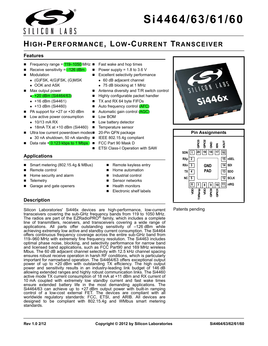
Features
Applications
Description
Pin Assignments
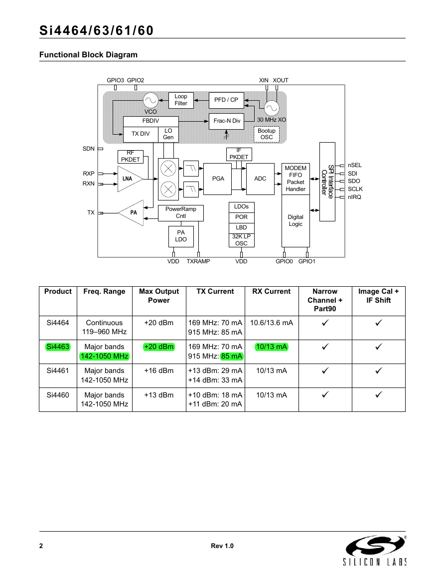
Functional Block Diagram
Product
Freq. Range
Max Output Power
TX Current
RX Current
Narrow Channel + Part90
Image Cal + IF Shift
Si4464
Continuous 119–960 MHz
+20 dBm
169 MHz: 70 mA
915 MHz: 85 mA
10.6/13.6 mA
ü
ü
Si4463
Major bands
142-1050 MHz
+20 dBm
169 MHz: 70 mA
915 MHz: 85 mA
10/13 mA
ü
ü
Si4461
Major bands
142-1050 MHz
+16 dBm
+13 dBm: 29 mA
+14 dBm: 33 mA
10/13 mA
ü
ü
Si4460
Major bands
142-1050 MHz
+13 dBm
+10 dBm: 18 mA
+11 dBm: 20 mA
10/13 mA
ü
ü
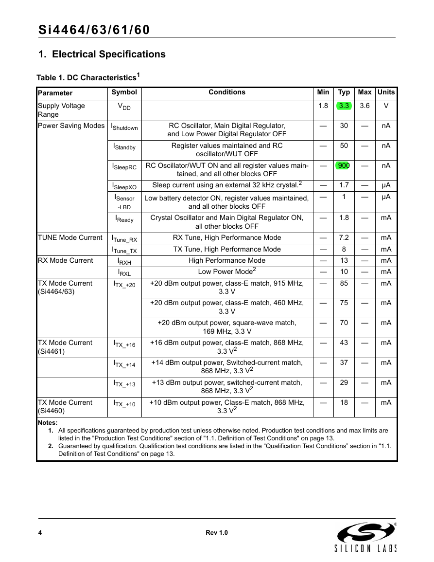
1. Electrical Specifications
Table 1. DC Characteristics1
Symbol
Conditions
Min
Typ
Max
Units
VDD
1.8
3.3
3.6
V
IShutdown
RC Oscillator, Main Digital Regulator, and Low Power Digital Regulator OFF
—
30
—
nA
IStandby
Register values maintained and RC oscillator/WUT OFF
—
50
—
nA
ISleepRC
RC Oscillator/WUT ON and all register values maintained, and all other blocks OFF
—
900
—
nA
ISleepXO
Sleep current using an external 32 kHz crystal.2
—
1.7
—
µA
ISensor -LBD
Low battery detector ON, register values maintained, and all other blocks OFF
—
1
—
µA
IReady
Crystal Oscillator and Main Digital Regulator ON, all other blocks OFF
—
1.8
—
mA
ITune_RX
RX Tune, High Performance Mode
—
7.2
—
mA
ITune_TX
TX Tune, High Performance Mode
—
8
—
mA
IRXH
High Performance Mode
—
13
—
mA
IRXL
Low Power Mode2
—
10
—
mA
ITX_+20
+20 dBm output power, class-E match, 915 MHz, 3.3 V
—
85
—
mA
+20 dBm output power, class-E match, 460 MHz, 3.3 V
—
75
—
mA
+20 dBm output power, square-wave match, 169 MHz, 3.3 V
—
70
—
mA
ITX_+16
+16 dBm output power, class-E match, 868 MHz, 3.3 V2
—
43
—
mA
ITX_+14
+14 dBm output power, Switched-current match, 868 MHz, 3.3 V2
—
37
—
mA
ITX_+13
+13 dBm output power, switched-current match, 868 MHz, 3.3 V2
—
29
—
mA
ITX_+10
+10 dBm output power, Class-E match, 868 MHz, 3.3 V2
—
18
—
mA
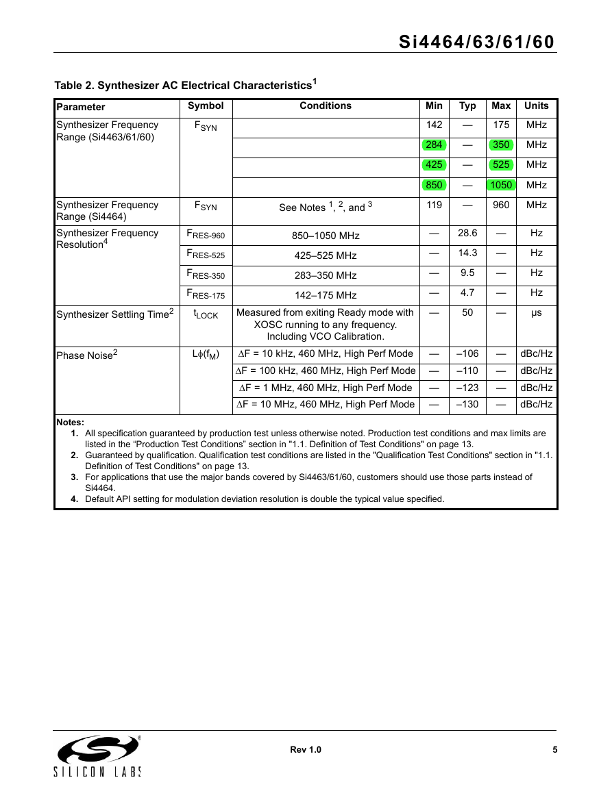
Table 2. Synthesizer AC Electrical Characteristics1
Symbol
Conditions
Min
Typ
Max
Units
FSYN
142
—
175
MHz
284
—
350
MHz
425
—
525
MHz
850
—
1050
MHz
FSYN
See Notes 1, 2, and 3
119
—
960
MHz
FRES-960
850–1050 MHz
—
28.6
—
Hz
FRES-525
425–525 MHz
—
14.3
—
Hz
FRES-350
283–350 MHz
—
9.5
—
Hz
FRES-175
142–175 MHz
—
4.7
—
Hz
tLOCK
Measured from exiting Ready mode with XOSC running to any frequency. Including VCO Calibration.
—
50
—
µs
Lf(fM)
DF = 10 kHz, 460 MHz, High Perf Mode
—
–106
—
dBc/Hz
DF = 100 kHz, 460 MHz, High Perf Mode
—
–110
—
dBc/Hz
DF = 1 MHz, 460 MHz, High Perf Mode
—
–123
—
dBc/Hz
DF = 10 MHz, 460 MHz, High Perf Mode
—
–130
—
dBc/Hz
Table 3. Receiver AC Electrical Characteristics1
Symbol
Conditions
Min
Typ
Max
Units
FRX
142
—
175
MHz
284
—
350
MHz
425
—
525
MHz
850
—
1050
MHz
FRX
See Notes 1, 2, 3, 4, and 5
119
—
960
MHz
PRX_0.5
(BER < 0.1%) (500 bps, GFSK, BT = 0.5, Df = ±250Hz)3
—
–126
—
dBm
PRX_40
(BER < 0.1%) (40 kbps, GFSK, BT = 0.5, Df = ±20 kHz)3
—
–110
—
dBm
PRX_100
(BER < 0.1%) (100 kbps, GFSK, BT = 0.5, Df = ±50 kHz)1
—
–106
—
dBm
PRX_125
(BER < 0.1%) (125 kbps, GFSK, BT = 0.5, Df = ±62.5 kHz)3
—
–105
—
dBm
PRX_500
(BER < 0.1%) (500 kbps, GFSK, BT = 0.5, Df = ±250 kHz)3
—
–97
—
dBm
PRX_9.6
(PER 1%) (9.6 kbps, 4GFSK, BT = 0.5, Df = ±2.4 kHz)3,4
—
–110
—
dBm
PRX_1M
(PER 1%) (1 Mbps, 4GFSK, BT = 0.5, Df = 1.25 kHz)3,4
—
–88
—
dBm
PRX_OOK
(BER < 0.1%, 4.8 kbps, 350 kHz BW, OOK, PN15 data)3
—
–109
—
dBm
(BER < 0.1%, 40 kbps, 350 kHz BW,
OOK, PN15 data)3
—
–104
—
dBm
(BER < 0.1%, 120 kbps, 350 kHz BW, OOK, PN15 data)3
—
–99
—
dBm
BW
1.1
—
850
kHz
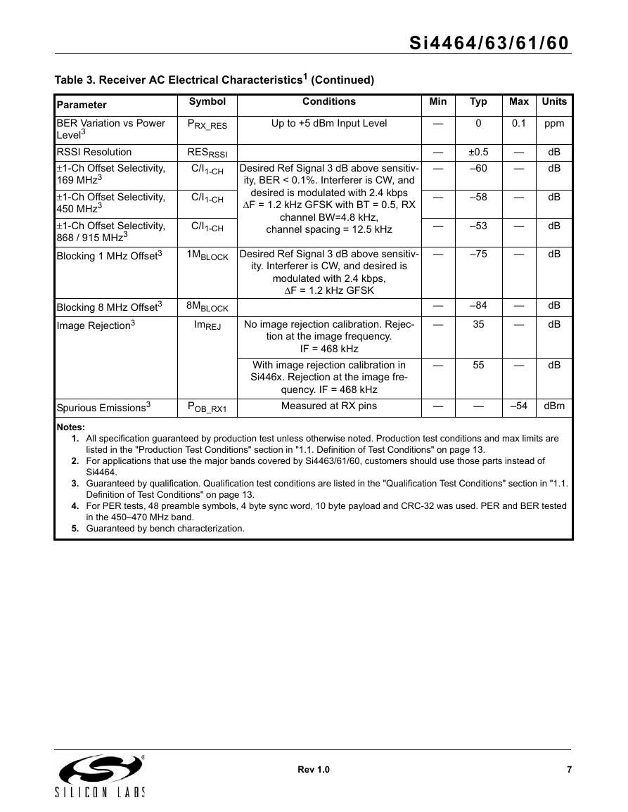
PRX_RES
Up to +5 dBm Input Level
—
0
0.1
ppm
RESRSSI
—
±0.5
—
dB
C/I1-CH
Desired Ref Signal 3 dB above sensitivity, BER < 0.1%. Interferer is CW, and desired is modulated with 2.4 kbps DF = 1.2 kHz GFSK with BT = 0.5, RX channel BW=4.8 kHz, channel spacing = 12.5 kHz
—
–60
—
dB
C/I1-CH
—
–58
—
dB
C/I1-CH
—
–53
—
dB
1MBLOCK
Desired Ref Signal 3 dB above sensitivity. Interferer is CW, and desired is modulated with 2.4 kbps, DF = 1.2 kHz GFSK
—
–75
—
dB
8MBLOCK
—
–84
—
dB
ImREJ
No image rejection calibration. Rejection at the image frequency. IF = 468 kHz
—
35
—
dB
With image rejection calibration in Si446x. Rejection at the image frequency. IF = 468 kHz
—
55
—
dB
POB_RX1
Measured at RX pins
—
—
–54
dBm
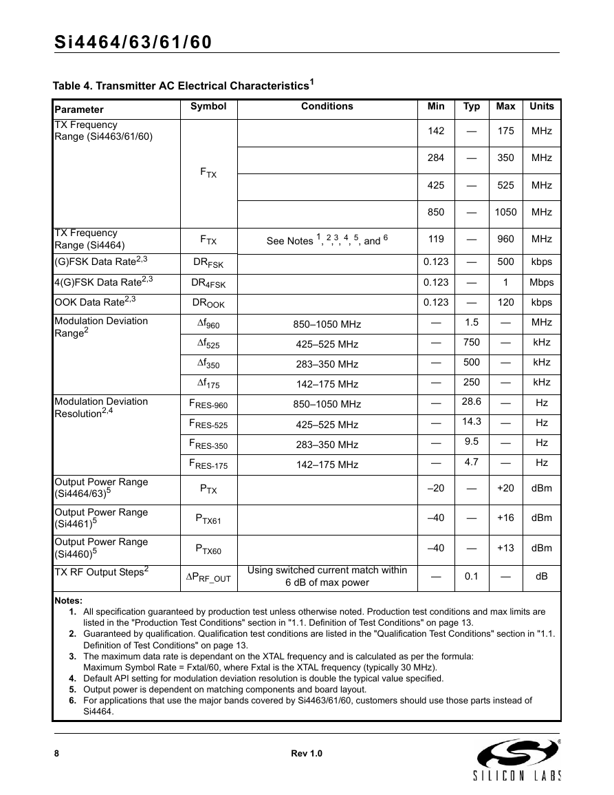
Table 4. Transmitter AC Electrical Characteristics1
Symbol
Conditions
Min
Typ
Max
Units
FTX
142
—
175
MHz
284
—
350
MHz
425
—
525
MHz
850
—
1050
MHz
FTX
See Notes 1, 2,3, 4, 5, and 6
119
—
960
MHz
DRFSK
0.123
—
500
kbps
DR4FSK
0.123
—
1
Mbps
DROOK
0.123
—
120
kbps
Df960
850–1050 MHz
—
1.5
—
MHz
Df525
425–525 MHz
—
750
—
kHz
Df350
283–350 MHz
—
500
—
kHz
Df175
142–175 MHz
—
250
—
kHz
FRES-960
850–1050 MHz
—
28.6
—
Hz
FRES-525
425–525 MHz
—
14.3
—
Hz
FRES-350
283–350 MHz
—
9.5
—
Hz
FRES-175
142–175 MHz
—
4.7
—
Hz
PTX
–20
—
+20
dBm
PTX61
–40
—
+16
dBm
PTX60
–40
—
+13
dBm
DPRF_OUT
Using switched current match within 6 dB of max power
—
0.1
—
dB
DPRF_TEMP
–40 to +85 °C
—
1
—
dB
DPRF_FREQ
Measured across 902–928 MHz
—
0.5
—
dB
B*T
Gaussian Filtering Bandwith Time Product
—
0.5
—
POB-TX1
POUT = +13 dBm, Frequencies <1 GHz
—
—
–54
dBm
POB-TX2
1–12.75 GHz, excluding harmonics
—
—
–42
dBm
P2HARM
Using reference design TX matching network and filter with max output power. Harmonics reduce linearly with output power.
—
—
–42
dBm
P3HARM
—
—
–42
dBm
Table 5. Auxiliary Block Specifications1
Symbol
Conditions
Min
Typ
Max
Units
TSS
—
1.78
—
mV/°C
LBDRES
—
50
—
mV
FMC
Configurable to Fxtal or Fxtal divided by 2, 3, 7.5, 10, 15, or 30 where Fxtal is the reference XTAL frequency. In addition, 32.768 kHz is also supported.
32.768K
—
Fxtal
Hz
TEMPCT
Programmable setting
—
3
—
ms
XTALRange
25
32
MHz
t30M
Using XTAL and board layout in reference design. Start-up time will vary with XTAL type and board layout.
—
250
—
µs
30MRES
—
70
—
fF
t32k
—
2
—
sec
32KRCRES
—
2500
—
ppm
tPOR
—
—
5
ms
Table 6. Digital IO Specifications (GPIO_x, SCLK, SDO, SDI, nSEL, nIRQ)1
Symbol
Conditions
Min
Typ
Max
Units
TRISE
0.1 x VDD to 0.9 x VDD, CL = 10 pF, DRV<1:0> = HH
—
2.3
—
ns
TFALL
0.9 x VDD to 0.1 x VDD, CL = 10 pF, DRV<1:0> = HH
—
2
—
ns
CIN
—
2
—
pF
VIH
VDD x 0.7
—
—
V
VIL
—
—
VDD x 0.3
V
IIN
0
–10
—
10
µA
IINP
VIL = 0 V
1
—
10
µA
IOmaxLL
DRV[1:0] = LL3
—
18.7
—
mA
IOmaxLH
DRV[1:0] = LH3
—
13.7
—
mA
IOmaxHL
DRV[1:0] = HL3
—
8.5
—
mA
IOmaxHH
DRV[1:0] = HH3
—
3
—
mA
IOmaxLL
DRV[1:0] = LL3
—
15.3
—
mA
IOmaxLH
DRV[1:0] = LH3
—
11.6
—
mA
IOmaxHL
DRV[1:0] = HL3
—
7.4
—
mA
IOmaxHH
DRV[1:0] = HH3
—
2.7
—
mA
IOmaxLL
DRV[1:0] = LL3
—
6.3
—
mA
IOmaxLH
DRV[1:0] = LH3
—
5.6
—
mA
IOmaxHL
DRV[1:0] = HL3
—
4.4
—
mA
IOmaxHH
DRV[1:0] = HH3
—
2.1
—
mA
VOH
DRV[1:0] = HL
VDD x 0.8
—
—
V
VOL
DRV[1:0] = HL
—
—
VDD x 0.2
V
Table 7. Absolute Maximum Ratings
Value
Unit
–0.3, +3.6
V
–0.3, +8.0
V
–0.3, +6.5
V
–0.3, VDD + 0.3
V
–0.3, VDD + 0.3
V
+10
dBm
–40 to +85
°C
30
°C/W
+125
°C
–55 to +125
°C
1.1. Definition of Test Conditions
2. Functional Description
Figure 1. Si4461 Direct-Tie Application Example
Figure 2. Si4463 Single Antenna with RF Switch Example
3. Controller Interface
3.1. Serial Peripheral Interface (SPI)
Table 8. Serial Interface Timing Parameters
Symbol
Parameter
Min (ns)
Diagram
tCH
Clock high time
40
tCL
Clock low time
40
tDS
Data setup time
20
tDH
Data hold time
20
tDD
Output data delay time
20
tEN
Output enable time
20
tDE
Output disable time
50
tSS
Select setup time
20
tSH
Select hold time
50
tSW
Select high period
80
Figure 3. SPI Write Command
Figure 4. SPI Read Command—Check CTS Value
Figure 5. SPI Read Command—Clock Out Read Data
3.2. Fast Response Registers
3.3. Operating Modes and Timing
Figure 6. State Machine Diagram
Table 9. Operating State Response Time and Current Consumption
State/Mode
Response Time to
Current in State /Mode
TX
RX
Shutdown State
15 ms
15 ms
30 nA
Standby State
Sleep State
SPI Active State
Ready State
TX Tune State
RX Tune State
460 µs
460 µs
300 µs
130 µs
65 µs
460 µs
460 µs
310 µs
140 µs
90 µs
50 nA
900 nA
1.35 mA
1.8 mA
8 mA
7.2 mA
TX State
—
120 µs
18 mA @ +10 dBm
RX State
120 µs
75 µs
10 or 13 mA
Figure 7. Start-Up Timing and Current Consumption using Shutdown State
Figure 8. Start-Up Timing and Current Consumption using Standby State
3.3.1. Shutdown State
3.3.2. Standby State
3.3.3. Sleep State
3.3.4. SPI Active State
3.3.5. Ready State
3.3.6. TX State
Figure 9. Start_TX Commands and Timing
3.3.7. RX State
3.4. Application Programming Interface (API)
Table 10. API Commands
Number
Name
Description
0x00
NOP
0x01
PART_INFO
0x02
POWER_UP
0x10
FUNC_INFO
0x11
SET_PROPERTY
0x12
GET_PROPERTY
0x13
GPIO_PIN_CFG
0x14
GET_SENSOR_READING
0x15
FIFO_RESET
0x20
GET_INT_STATUS
0x21
GET_PH_STATUS
0x22
GET_MODEM_STATUS
0x23
GET_CHIP_STATUS
0x31
START_TX
0x32
START_RX
0x33
REQUEST_DEVICE_
STATE
0x34
CHANGE_STATE
0x50
FAST RESPONSE A
0x51
FAST RESPONSE B
0x53
FAST RESPONSE C
0x57
FAST RESPONSE D
0x66
TX_FIFO_WRITE
0x77
RX_FIFO_READ
3.5. START_TX
START_TX Command
7
6
5
4
3
2
1
0
CMD
0x31
CHANNEL
CHANNEL[7:0]
CONDITION
TXCOMPLETE_STATE[3:0]
0
RETRANSMIT
START[1:0]
TX_LEN
TX_LEN[15:8]
TX_LEN
TX_LEN[7:0]
START_TX Reply
7
6
5
4
3
2
1
0
CMD_COMPLETE
CTS[7:0]
3.6. Interrupts
Number
Command
Summary
0x20
GET_INT_STATUS
0x21
GET_PH_STATUS
0x22
GET_MODEM_STATUS
0x23
GET_CHIP_STATUS
Number
Property
Default
Summary
0x0100
INT_CTL_ENABLE
0x04
0x0101
INT_CTL_PH_ENABLE
0x00
0x0102
INT_CTL_MODEM_ENABLE
0x00
0x0103
INT_CTL_CHIP_ENABLE
0x04
3.7. GPIO
Table 11. GPIOs
Pin
SDN State
POR Default
GPIO0
0
POR
GPIO1
0
CTS
GPIO2
0
POR
GPIO3
0
POR
nIRQ
resistive VDD pull-up
nIRQ
SDO
resistive VDD pull-up
SDO
SDI
High Z
SDI
4. Modulation and Hardware Configuration Options
4.1. MODEM_MOD_TYPE
MODEM_MOD_TYPE
7
6
5
4
3
2
1
0
TX_DIRECT_MODE_TYPE
TX_DIRECT_MODE_GPIO[1:0]
MOD_SOURCE[1:0]
MOD_TYPE[2:0]
0
0x0
0x0
0x2
4.2. Modulation Types
4.3. Hardware Configuration Options
4.3.1. Receive Demodulator Options
4.3.2. RX/TX Data Interface With MCU
4.4. Preamble Length
Table 12. Recommended Preamble Length
Mode
AFC
Antenna Diversity
Preamble Type
Recommended Preamble Length
Recommended Preamble Detection Threshold
(G)FSK
Disabled
Disabled
Standard
4 Bytes
20 bits
(G)FSK
Enabled
Disabled
Standard
5 Bytes
20 bits
(G)FSK
Disabled
Disabled
Non-standard
2 Bytes
0 bits
(G)FSK
Enabled
Non-standard
Not Supported
(G)FSK
Disabled
Enabled
Standard
7 Bytes
24 bits
(G)FSK
Enabled
Enabled
Standard
8 Bytes
24 bits
4(G)FSK
Disabled
Disabled
Standard
40 symbols
16 symbols
4(G)FSK
Enabled
Disabled
Standard
48 symbols
16 symbols
4(G)FSK
Non-standard
Not Supported
OOK
Disabled
Disabled
Standard
4 Bytes
20 bits
OOK
Disabled
Disabled
Non-standard
2 Bytes
0 bits
OOK
Enabled
Not Supported
5. Internal Functional Blocks
5.1. RX Chain
5.1.1. RX Chain Architecture
Figure 10. RX Architecture vs. Data Rate
5.2. RX Modem
5.2.1. Automatic Gain Control (AGC)
5.2.2. Auto Frequency Correction (AFC)
5.2.3. Image Rejection and Calibration
5.2.4. Received Signal Strength Indicator
5.3. Synthesizer
5.3.1. Synthesizer Frequency Control
Table 13. Output Divider (Outdiv) Values for the Si4460/61/63
Outdiv
Lower (MHz)
Upper (MHz)
24
142
175
12
284
350
8
425
525
4
850
1050
Table 14. Output Divider (Outdiv) for the Si4464
Outdiv
Lower (MHz)
Upper (MHz)
24
119
168.99
16
169
224.99
12
225
337.99
8
338
449.99
6
450
675.99
4
675
960
5.4. Transmitter (TX)
Number
Command
Summary
0x2200
PA_MODE
0x2201
PA_PWR_LVL
0x2202
PA_BIAS_CLKDUTY
0x2203
PA_TC
5.4.1. Si4464/63: +20 dBm PA
Figure 11. +20 dBm TX Power vs. PA_PWR_LVL
Figure 12. +20 dBm TX Power vs. VDD
Figure 13. +20 dBm TX Power vs. Temp
5.4.2. Si4461 +16 dBm PA
Figure 14. +13 dBm TX Power vs. PA_PWR_LVL
Figure 15. +13 dBm TX Power vs. Supply Voltage (VDD)
5.5. Crystal Oscillator
Figure 16. Capacitor Bank Frequency Offset Characteristics
6. Data Handling and Packet Handler
6.1. RX and TX FIFOs
Figure 17. TX and RX FIFOs
6.2. Packet Handler
Figure 18. Packet Handler Structure
7. RX Modem Configuration
8. Auxiliary Blocks
8.1. Wake-up Timer and 32 kHz Clock Source
Table 15. WUT Specific Commands and Properties
API Properties
Description
Requirements/Notes
GLOBAL_WUT_CONFIG
GLOBAL WUT configuration
GLOBAL_WUT_M_15_8
Sets HW WUT_M[15:8]
GLOBAL_ WUT_M_7_0
Sets HW WUT_M[7:0]
GLOBAL_WUT_R
Sets WUT_R[4:0]
Sets WUT_SLEEP to choose WUT state
GLOBAL_WUT_LDC
Sets FW internal WUT_LDC
Table 16. WUT Related API Commands and Properties
Command/Property
Description
Requirements/Notes
WUT Interrupt Enable
INT_CTL_ENABLE
Interrupt enable property
INT_CTL_CHIP_ENABLE
Chip interrupt enable property
32 kHz Clock Source Selection
GLOBAL_CLK_CFG
Clock configuration options
WUT Interrupt Output
GPIO_PIN_CFG
Host can enable interrupt on WUT expire
RX/TX Operation
START_RX/TX
START RX/TX when wake up timer expire
8.2. Low Duty Cycle Mode (Auto RX Wake-Up)
Figure 19. RX and TX LDC Sequences
Figure 20. Low Duty Cycle Mode for RX
8.3. Temperature, Battery Voltage, and Auxiliary ADC
GET_ADC_READING Command
7
6
5
4
3
2
1
0
CMD
0x14
ADC_EN
0
TEMPERATURE_EN
BATTERY_VOLTAGE_EN
ADC_GPIO_EN
ADC_GPIO_PIN[1:0]
GET_ADC_READING Reply
7
6
5
4
3
2
1
0
CMD_COMPLETE
CTS[7:0]
GPIO_ADC
GPIO_ADC[15:8]
GPIO_ADC
GPIO_ADC[7:0]
BATTERY_ADC
BATTERY_ADC[15:8]
BATTERY_ADC
BATTERY_ADC[7:0]
TEMP_ADC
TEMP_ADC[15:8]
TEMP_ADC
TEMP_ADC[7:0]
TEMP_SLOPE
TEMP_SLOPE[7:0]
TEMP_INTERCEPT
TEMP_INTERCEPT[7:0]
8.4. Low Battery Detector
8.5. Antenna Diversity
9. Pin Descriptions: Si4464/63/62/61/60
Pin
Pin Name
I/0
Description
1
SDN
I
2
RXp
I
3
RXn
I
4
TX
O
5
NC
6
VDD
VDD
7
TXRAMP
O
8
VDD
VDD
9
GPIO0
I/O
10
GPIO1
I/O
11
nIRQ
O
12
SCLK
I
13
SDO
O
14
SDI
I
15
nSEL
I
16
XOUT
O
17
XIN
I
18
GND
GND
19
GPIO2
I/O
20
GPIO3
I/O
PKG
PADDLE_GND
GND
10. Ordering Information
Part Number1,2
Description
Package Type
Operating Temperature
Si4464-Bxx-FM
QFN-20
Pb-free
–40 to 85 °C
Si4463-Bxx-FM
QFN-20
Pb-free
–40 to 85 °C
Si4461-Bxx-FM
QFN-20
Pb-free
–40 to 85 °C
Si4460-Bxx-FM
QFN-20
Pb-free
–40 to 85 °C
11. Package Outline: Si4464/63/61/60
Figure 21. 20-Pin Quad Flat No-Lead (QFN)
Table 17. Package Dimensions
Symbol
Millimeters
Min
Nom
Max
A
0.80
0.85
0.90
A1
0.00
0.02
0.05
b
0.18
0.25
0.30
D
4.00 BSC
D2
2.45
2.60
2.75
e
0.50 BSC
E
4.00 BSC
E2
2.45
2.60
2.75
L
0.30
0.40
0.50
aaa
—
—
0.15
bbb
—
—
0.08
ccc
—
—
0.10
ddd
—
—
0.10
eee
—
—
0.10
ggg
—
—
0.05
12. PCB Land Pattern: Si4464/63/61/60
Figure 22. PCB Land Pattern
Table 18. PCB Land Pattern Dimensions
Symbol
Millimeters
Min
Max
C1
3.90
4.00
C2
3.90
4.00
E
0.50 REF
X1
0.20
0.30
X2
2.55
2.65
Y1
0.65
0.75
Y2
2.55
2.65
13. Top Marking
13.1. Si4464/63/61/60 Top Marking
13.2. Top Marking Explanation
Document Change List
Contact Information



 2023年江西萍乡中考道德与法治真题及答案.doc
 2012年重庆南川中考生物真题及答案.doc
 2013年江西师范大学地理学综合及文艺理论基础考研真题.doc
 2020年四川甘孜小升初语文真题及答案I卷.doc
 2020年注册岩土工程师专业基础考试真题及答案.doc
 2023-2024学年福建省厦门市九年级上学期数学月考试题及答案.doc
 2021-2022学年辽宁省沈阳市大东区九年级上学期语文期末试题及答案.doc
 2022-2023学年北京东城区初三第一学期物理期末试卷及答案.doc
 2018上半年江西教师资格初中地理学科知识与教学能力真题及答案.doc
 2012年河北国家公务员申论考试真题及答案-省级.doc
 2020-2021学年江苏省扬州市江都区邵樊片九年级上学期数学第一次质量检测试题及答案.doc
 2022下半年黑龙江教师资格证中学综合素质真题及答案.doc