• In Part I, we will first introduce the mutipath propagation effects and
Doppler frequency shift/spread effects.
• In Part II, we will briefly introduce multipath and Doppler channel models.
Multipath and Doppler Effects and Models
There are two parts in this lecture.
1
�
Background: Overviews on Wireless Channel Modeling
We need to ask the following three important questions while designing a wireless
communication link:
1. Fading & Power Loss:
Is the signal to interference plus noise ratio (SINR) large enough for the receiver
to detect the transmitted signal?
2. Signal Distortion:
Can the signal distortion be ignored, predicted or removed so that we know how
to recover the transmitted information at the receiver?
3. Time Variation:
Can the receiver adapt faster enough to the variations of the above two features
(SINR & signal distortion)?
A complete wireless channel model should provide quantitative measures of SINR,
signal distortion and time variation.
For SINR (referred in question 1), we need only to consider the time invariant
transmission loss at a single frequency (that is the RF carrier frequency). The
frequency and time dependent properties of signal can be addressed in answering
questions 2 and 3.
Signal distortion (referred in question 2) is caused by the frequency dependent
variations of the received signal strength and phase. The primary source of
frequency dependent variations is multipath propagation. Here, we need only to
consider time invariant situations and leave the time varying features to question 3.
Motions of receivers, transmitters or wireless environments generate Doppler
effects. With Doppler effects, signal frequencies shift and spread. These Doppler
effects will cause time variations in the received signal strength and wave shape.
This kind of time varying features is usually random and can be modeled as
stochastic processes.
In order to addressing these three important issues, we divide wireless channel modeling
into three parts:
-single frequency (or narrowband signal)
• Transmission loss
-time invariant environment (or short observation time period)
• Frequency dependent channel impulse response or transfer function
-time invariant environment (or short observation time period)
• Time varying channel impulse response or transfer function
-multiple frequencies (or broadband signal)
-multiple frequencies (or broadband signal)
2
�
-time varying environment (or long observation time period)
We have discussed transmission loss (including path loss, short term fading and long
term fading) of a single frequency response in time invariant environments in the
previous lecture. Both frequency dependent and time varying features of a channel
impulse response (or transfer function) will be introduced in this lecture.
3
�
Part I: Multipath and Doppler Effects
After studying this note, students will be able to
1. Understand multipath channel effects in both time and frequency domains
2. Understand Doppler effects in both time and frequency domains
3. Understand multipath and Doppler effects in both time and frequency domains
I. Multipath Channel Effects: Time Invariant Case (No Doppler effects)
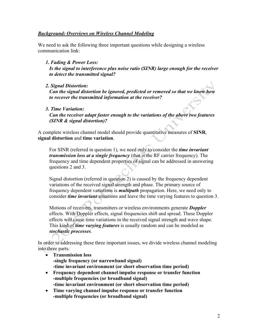
In wireless communication environments, a signal transmitted from the transmitter
reaches the receiver through many different paths as illustrated in Figure 1.
Figure 1: Multipath propagation
Let s(t) is the transmitted signal. The received signal can then be written as a sum of
multipath arrivals:
y t
( )
a s t τ τ τ τ
i
3
),
τ
L
....
=
−
≤
≤
≤
≤
(
i
1
2
(1)
L
∑
i
1
=
Here, L is the total number of multipath arrivals, ai and τi are the amplitude and arrival
time of the ith ray, respectively.
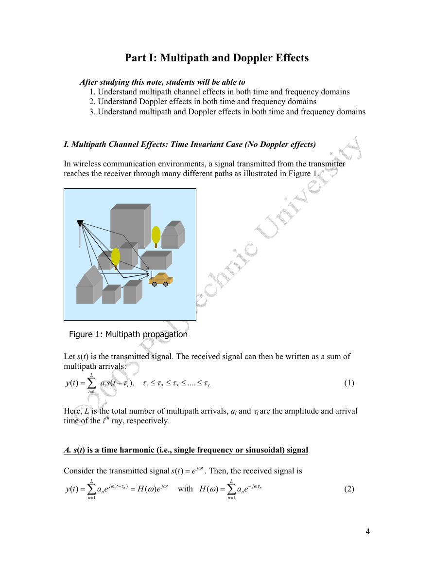
A. s(t) is a time harmonic (i.e., single frequency or sinusoidal) signal
s t
Consider the transmitted signal ( )
. Then, the received signal is
e ω=
j
t
y t
( )
=
L
∑
n
1
=
a e
n
j
ω τ
n
−
(
t
)
=
H
(
j
t
ωω
e
)
with
H
(
)
ω
=
L
∑
n
1
=
−
j
ωτ
n
a e
n
(2)
4
�
(
(
)H ω is defined as the transfer function of the multipath environment. Note that
Here,
the receiver signal y(t) remains as a time harmonic signal with the same angular
frequency ω as the transmitted signal s(t). Thus, no distortion in wave shape has
occurred during the transmission of s(t) through a time invariant multipath environment.
)H ω
However, the magnitude of the signal has been modified. The new magnitude is
which is a function of angular frequency ω.
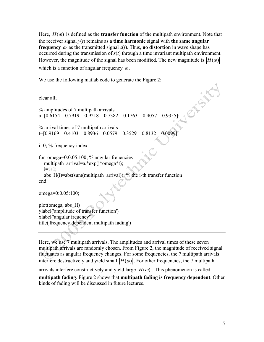
We use the following matlab code to generate the Figure 2:
========================================================
clear all;
% amplitudes of 7 multipath arrivals
a=[0.6154 0.7919 0.9218 0.7382 0.1763 0.4057 0.9355];
% arrival times of 7 multipath arrivals
t=[0.9169 0.4103 0.8936 0.0579 0.3529 0.8132 0.0099];
i=0; % frequency index
for omega=0:0.05:100; % angular freuencies
multipath_arrival=a.*exp(j*omega*t);
i=i+1;
abs_H(i)=abs(sum(multipath_arrival)); % the i-th transfer function
end
omega=0:0.05:100;
plot(omega, abs_H)
ylabel('amplitude of transfer function')
xlabel('angular freuency')
title('frequency dependent multipath fading')
Here, we use 7 multipath arrivals. The amplitudes and arrival times of these seven
multipath arrivals are randomly chosen. From Figure 2, the magnitude of received signal
fluctuates as angular frequency changes. For some frequencies, the 7 multipath arrivals
interfere destructively and yield small
arrivals interfere constructively and yield large
multipath fading. Figure 2 shows that multipath fading is frequency dependent. Other
kinds of fading will be discussed in future lectures.
)H ω . This phenomenon is called
)H ω . For other frequencies, the 7 multipath
(
(
5
�
Since the amplitudes and arrival times of multipath arrivals depend on locations of
transmitter and receiver, the received signal strength will also depend on the locations of
transmitter and receiver.
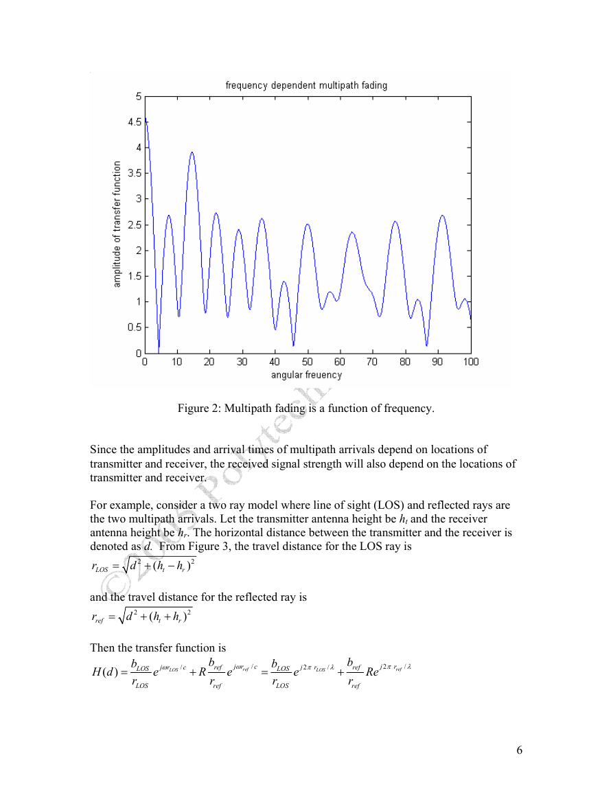
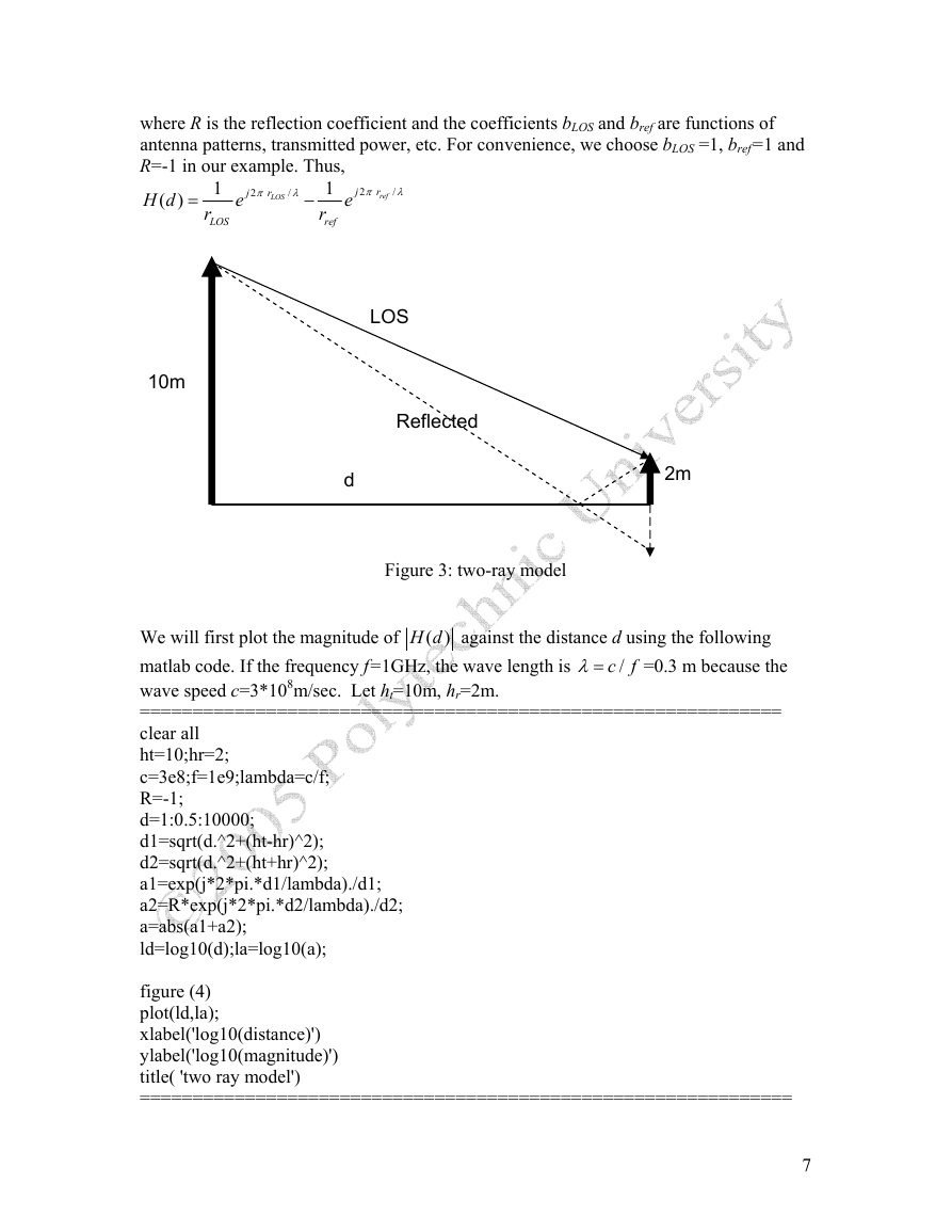
For example, consider a two ray model where line of sight (LOS) and reflected rays are
the two multipath arrivals. Let the transmitter antenna height be ht and the receiver
antenna height be hr. The horizontal distance between the transmitter and the receiver is
denoted as d. From Figure 3, the travel distance for the LOS ray is
r
LOS
and the travel distance for the reflected ray is
r
ref
Then the transfer function is
b
ref
H d
e
( )
r
ref
b
LOS
r
LOS
b
LOS
r
LOS
b
ref
r
ref
Re
h
r
h
r
h
t
j
2
π
(
h
t
j
2
π
r
ref
j r
ω
ref
2
)
2
)
r
LOS
/
λ
+
(
R
j r
ω
LOS
/
c
2
d
=
2
d
+
/
λ
/
c
=
−
+
=
=
e
+
e
+
Figure 2: Multipath fading is a function of frequency.
6
�
where R is the reflection coefficient and the coefficients bLOS and bref are functions of
antenna patterns, transmitted power, etc. For convenience, we choose bLOS =1, bref=1 and
R=-1 in our example. Thus,
H d
e
( )
r
2
π
LOS
2
π
1
e
=
−
/
λ
j
r
ref
/
λ
j
r
LOS
1
r
ref
LOS
Reflected
d
2m
10m
Figure 3: two-ray model
λ=
/c f
=0.3 m because the
( )H d against the distance d using the following
We will first plot the magnitude of
matlab code. If the frequency f=1GHz, the wave length is
wave speed c=3*108m/sec. Let ht=10m, hr=2m.
=============================================================
clear all
ht=10;hr=2;
c=3e8;f=1e9;lambda=c/f;
R=-1;
d=1:0.5:10000;
d1=sqrt(d.^2+(ht-hr)^2);
d2=sqrt(d.^2+(ht+hr)^2);
a1=exp(j*2*pi.*d1/lambda)./d1;
a2=R*exp(j*2*pi.*d2/lambda)./d2;
a=abs(a1+a2);
ld=log10(d);la=log10(a);
figure (4)
plot(ld,la);
xlabel('log10(distance)')
ylabel('log10(magnitude)')
title( 'two ray model')
==============================================================
7
�
)H f
(
against the frequency f for four distances
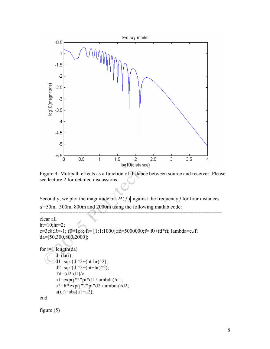
Figure 4: Mutipath effects as a function of distance between source and receiver. Please
see lecture 2 for detailed discussions.
Secondly, we plot the magnitude of
d=50m, 300m, 800m and 2000m using the following matlab code:
=============================================================
clear all
ht=10;hr=2;
c=3e8;R=-1; f0=1e8; fi= [1:1:1000];fd=5000000;f= f0+fd*fi; lambda=c./f;
da=[50,300,800,2000];
for i=1:length(da)
end
figure (5)
d=da(i);
d1=sqrt(d.^2+(ht-hr)^2);
d2=sqrt(d.^2+(ht+hr)^2);
Td=(d2-d1)/c
a1=exp(j*2*pi*d1./lambda)/d1;
a2=R*exp(j*2*pi*d2./lambda)/d2;
a(i,:)=abs(a1+a2);
8
�




 2023年江西萍乡中考道德与法治真题及答案.doc
 2012年重庆南川中考生物真题及答案.doc
 2013年江西师范大学地理学综合及文艺理论基础考研真题.doc
 2020年四川甘孜小升初语文真题及答案I卷.doc
 2020年注册岩土工程师专业基础考试真题及答案.doc
 2023-2024学年福建省厦门市九年级上学期数学月考试题及答案.doc
 2021-2022学年辽宁省沈阳市大东区九年级上学期语文期末试题及答案.doc
 2022-2023学年北京东城区初三第一学期物理期末试卷及答案.doc
 2018上半年江西教师资格初中地理学科知识与教学能力真题及答案.doc
 2012年河北国家公务员申论考试真题及答案-省级.doc
 2020-2021学年江苏省扬州市江都区邵樊片九年级上学期数学第一次质量检测试题及答案.doc
 2022下半年黑龙江教师资格证中学综合素质真题及答案.doc