logo资料库

PLCopen part4.pdf

第1页 / 共119页
第2页 / 共119页
第3页 / 共119页
第4页 / 共119页
第5页 / 共119页
第6页 / 共119页
第7页 / 共119页
第8页 / 共119页
资料共119页,剩余部分请下载后查看
Start of Document
Contributors
Versions
Table of Contents
1 General
1.1 Objectives
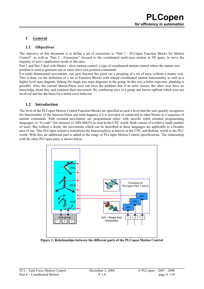
1.2 Introduction
1.3 Overview of the defined Function Blocks
1.3.1 Length of FB names and ways to shorten them
1.4 Glossary
2 Principles of Coordinated Motion
2.1 Coordinate System and kinematic transformation
2.1.1 Kinematic Transformation
2.2 How do commands behave in dynamic coordinate systems
2.3 Movements
2.4 Blending and Buffering of Movements
2.4.1 General Information
2.4.2 Overview of Buffer Modes
2.4.3 Overview of Transition Modes
2.4.4 Matrix of available transition modes
3 Model
3.1 State diagram
3.2 Relationship Single Axis and Grouped Axes State Diagrams
3.3 Input Execution Mode
4 Axes Grouping
4.1 Creating and using an AxesGroup
5 Function Blocks for Coordinated Motion
5.1 MC_AddAxisToGroup
5.2 MC_RemoveAxisFromGroup
5.3 MC_UngroupAllAxes
5.4 MC_GroupReadConfiguration
5.5 MC_GroupEnable
5.6 MC_GroupDisable
5.7 MC_GroupHome
5.8 Transformation FBs
5.8.1 MC_SetKinTransform (ACS to MCS)
5.8.2 MC_SetCartesianTransform (MCS to PCS)
5.8.3 MC_SetCoordinateTransform (MCS to PCS)
5.8.4 MC_ReadKinTransform (ACS to MCS)
5.8.5 MC_ReadCartesianTransform (MCS to PCS)
5.8.6 MC_ReadCoordinateTransform (MCS to PCS)
5.9 MC_GroupSetPosition
5.10 MC_GroupReadActualPosition
5.11 MC_GroupReadActualVelocity
5.12 MC_GroupReadActualAcceleration
5.13 MC_GroupStop
5.14 MC_GroupHalt
5.15 MC_GroupInterrupt
5.16 MC_GroupContinue
5.17 MC_GroupReadStatus
5.18 MC_GroupReadError
5.19 MC_GroupReset
5.20 MC_MoveLinearAbsolute
5.21 MC_MoveLinearRelative
5.22 MC_MoveCircularAbsolute
5.23 MC_MoveCircularRelative
5.24 MC_MoveDirectAbsolute
5.25 MC_MoveDirectRelative
5.26 MC_PathSelect
5.27 MC_MovePath
5.28 MC_GroupSetOverride
6 Axes Group Synchronized Motion
6.1 Synchronization
6.1.1 Synchronization of single axis to an axes group
6.1.2 Synchronization of an axes group to a single axis
6.2 Tracking
6.3 MC_SyncAxisToGroup
6.4 MC_SyncGroupToAxis
6.5 MC_SetDynCoordTransform
6.6 MC_TrackConveyorBelt
6.7 MC_TrackRotaryTable
7 Details of Blending and Buffering of Movements
7.1 Terminological definitions
7.2 Input parameter for blending
7.3 Buffer Modes
7.3.1 BufferMode “Aborting”
7.3.2 BufferMode “Buffered”
7.3.3 BufferMode “Blending”
7.4 TransitionMode
7.4.1 TransitionMode “TMNone” (insert no transition curve)
7.4.2 TransitionMode “TMStartVelocity” (Transition with given maximum velocity)
7.4.3 TransitionMode “TMConstantVelocity”(Transition with given constant velocity)
7.4.4 TransitionMode “TMCornerDistance” (Transition with given corner distance)
7.4.5 TransitionMode “TMMaxCornerDeviation” (Transition with given maximum corner deviation)
Appendix 1. Compliance Procedure and Compliance List
Appendix 1.1. Statement of Supplier
Appendix 1.2. Supported Data types
Appendix 1.3. Supported Buffer Modes
Appendix 1.4. Supported Transition Modes
Appendix 1.5. Short overview of the Function Blocks
Appendix 1.6. The PLCopen Motion Control Logo and Its Usage
PLCopen for efficiency in automation Technical Paper PLCopen Technical Committee 2 – Task Force Function Blocks for motion control: Part 4 –Coordinated Motion PLCopen Document Version 1.0, Published DISCLAIMER OF WARANTIES THIS DOCUMENT IS PROVIDED ON AN “AS IS” BASIS AND MAY BE SUBJECT TO FUTURE ADDITIONS, MODIFICATIONS, OR CORRECTIONS. PLCOPEN HEREBY DISCLAIMS ALL WARRANTIES OF ANY KIND, EXPRESS OR IMPLIED, INCLUDING ANY WARRANTY OF MERCHANTABILITY OR FITNESS FOR A PARTICULAR PURPOSE, FOR THIS DOCUMENT. IN NO EVENT WILL PLCOPEN BE RESPONSIBLE FOR ANY LOSS OR DAMAGE ARISING OUT OR RESULTING FROM ANY DEFECT, ERROR OR OMISSION IN THIS DOCUMENT OR FROM ANYONE’S USE OF OR RELIANCE ON THIS DOCUMENT. Copyright © 2002 - 2008 by PLCopen. All rights reserved. Date: December 3, 2008 Total number of pages: 119
Function blocks for motion control PLCopen for efficiency in automation 3S – Smart Software Solutions ABB Beckhoff Beckhoff Beckhoff Bosch Rexroth B & R B & R Control Techniques Danfoss Eckelmann GE Fanuc ISG ISG Keba Kuka Robotics Omron Omron Omron Parker Hannifin Phoenix Contact SEW Eurodrive Siemens Automation & Drives Siemens Automation & Drives Schneider Electric Motion Deutschland (formerly Berger Lahr) Schneider Electric Motion Deutschland (formerly Berger Lahr) TetraPak PLCopen The following paper is a document under construction within the PLCopen Task Force Motion Control. As such it is an addition to the PLCopen Task Force Motion Control, Technical Document Version 1.0. It summarizes the results of the PLCopen Task Force Motion Control, containing contributions of all its members. The present specification was written thanks to the following members of the Task Force: Hilmar Panzer Christian Müller Klaus Bernzen Josef Papenfort Wilfried Plaß Wolfgang Czech Friedrich Forthuber Martin Schrott Ed Baker Roland Schaumburg Ryszard Bochniak Djafar Hadiouche Jürgen Hipp Joachim Mayer Harald Buchgeher Joachim Strobel Candido Ferrio Josep Lario Yoshikazu Tachibana Christian Ruf Klas Hellmann Markus Müller Willi Gagsteiger Hans Peter Otto Jürgen Fieß Wolfgang Fien Istvan Ulvros Eelco van der Wal Change Status List: Version number V 0.1 V 0.2 V 0.3 V 0.4 V 0.5 V 0.6 V 0.6a Initial version as generated by EvdW As result of meeting with Klas Hellmann, Joachim Mayer and EvdWal As send to group. Includes feedback KH, JM and EvdWal As result of kick off meeting at Siemens As result of the meeting near Amsterdam As result of the meeting at Kuka. Not released. New order in FBs. Pictures added in Ch. 2. Homework ISG on transformation FBs added As result of the Meeting at Salzburg, and items of workgroups 1 & 3 As result of the meeting in Sitges, Spain As a result of the meeting at Control Techniques. All changes accepted from V 0.8 As result of the meeting in Hamburg V 0.7 V 0.8 V 0.9 March 13, 2006 May 10 & 11, 2006 July 5 & 6, 2006 V 0.91 September 20, 2006 April 27, 2005 May 3, 2005 May 20, 2005 July 14, 2005 Sept. 9, 2005 Dec 14, 2005 Dec 21, 2005 Date Change comment TC2 - Task Force Motion Control Part 4 – Coordinated Motion December 3, 2008 V 1.0 © PLCopen – 2007 - 2008 page 2/ 119
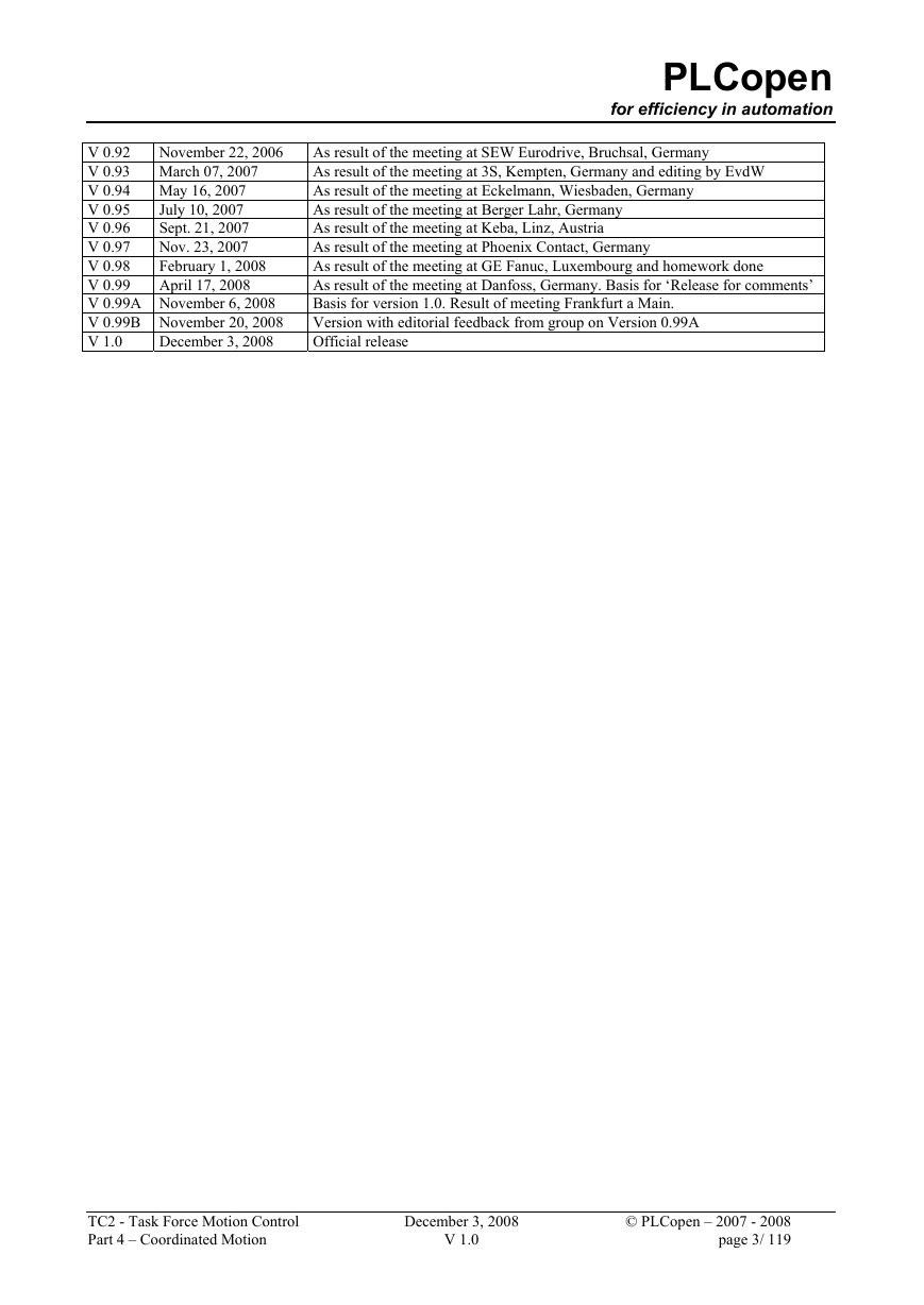
PLCopen for efficiency in automation As result of the meeting at SEW Eurodrive, Bruchsal, Germany As result of the meeting at 3S, Kempten, Germany and editing by EvdW As result of the meeting at Eckelmann, Wiesbaden, Germany As result of the meeting at Berger Lahr, Germany As result of the meeting at Keba, Linz, Austria As result of the meeting at Phoenix Contact, Germany As result of the meeting at GE Fanuc, Luxembourg and homework done As result of the meeting at Danfoss, Germany. Basis for ‘Release for comments’ Basis for version 1.0. Result of meeting Frankfurt a Main. Version with editorial feedback from group on Version 0.99A Official release November 22, 2006 V 0.92 V 0.93 March 07, 2007 V 0.94 May 16, 2007 V 0.95 July 10, 2007 Sept. 21, 2007 V 0.96 Nov. 23, 2007 V 0.97 February 1, 2008 V 0.98 V 0.99 April 17, 2008 V 0.99A November 6, 2008 V 0.99B November 20, 2008 V 1.0 December 3, 2008 TC2 - Task Force Motion Control Part 4 – Coordinated Motion December 3, 2008 V 1.0 © PLCopen – 2007 - 2008 page 3/ 119
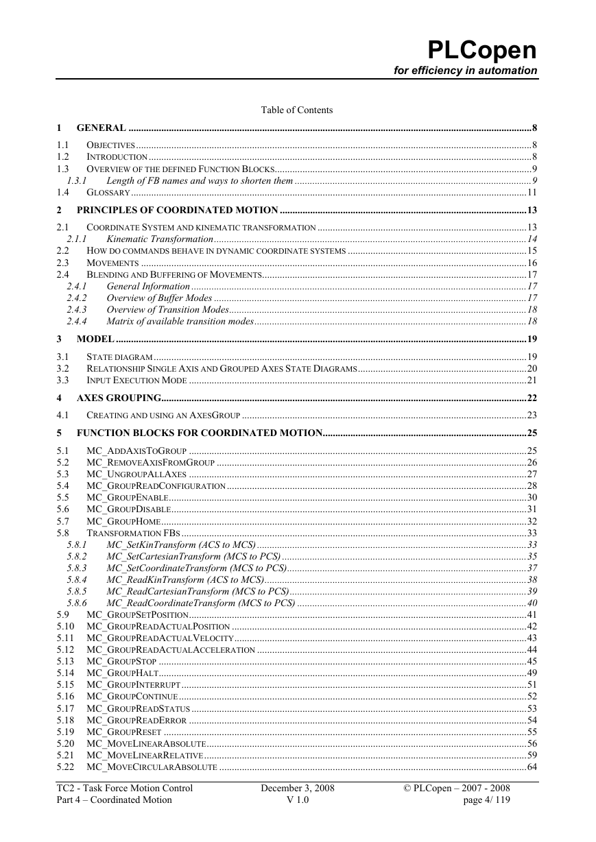
Table of Contents PLCopen for efficiency in automation 1.3.1 2.1.1 2.4.1 2.4.2 2.4.3 2.4.4 1 GENERAL ................................................................................................................................................................8 1.1 OBJECTIVES.............................................................................................................................................................8 1.2 INTRODUCTION........................................................................................................................................................8 1.3 OVERVIEW OF THE DEFINED FUNCTION BLOCKS......................................................................................................9 Length of FB names and ways to shorten them ..............................................................................................9 1.4 GLOSSARY.............................................................................................................................................................11 2 PRINCIPLES OF COORDINATED MOTION ..................................................................................................13 2.1 COORDINATE SYSTEM AND KINEMATIC TRANSFORMATION ...................................................................................13 Kinematic Transformation............................................................................................................................14 2.2 HOW DO COMMANDS BEHAVE IN DYNAMIC COORDINATE SYSTEMS .......................................................................15 2.3 MOVEMENTS .........................................................................................................................................................16 2.4 BLENDING AND BUFFERING OF MOVEMENTS.........................................................................................................17 General Information .....................................................................................................................................17 Overview of Buffer Modes ............................................................................................................................17 Overview of Transition Modes......................................................................................................................18 Matrix of available transition modes............................................................................................................18 3 MODEL ...................................................................................................................................................................19 3.1 STATE DIAGRAM....................................................................................................................................................19 3.2 RELATIONSHIP SINGLE AXIS AND GROUPED AXES STATE DIAGRAMS...................................................................20 3.3 INPUT EXECUTION MODE ......................................................................................................................................21 4 AXES GROUPING.................................................................................................................................................22 4.1 CREATING AND USING AN AXESGROUP .................................................................................................................23 5 FUNCTION BLOCKS FOR COORDINATED MOTION.................................................................................25 5.1 MC_ADDAXISTOGROUP ......................................................................................................................................25 5.2 MC_REMOVEAXISFROMGROUP ...........................................................................................................................26 5.3 MC_UNGROUPALLAXES ......................................................................................................................................27 5.4 MC_GROUPREADCONFIGURATION.......................................................................................................................28 5.5 MC_GROUPENABLE..............................................................................................................................................30 5.6 MC_GROUPDISABLE.............................................................................................................................................31 5.7 MC_GROUPHOME.................................................................................................................................................32 5.8 TRANSFORMATION FBS.........................................................................................................................................33 MC_SetKinTransform (ACS to MCS) ...........................................................................................................33 MC_SetCartesianTransform (MCS to PCS) .................................................................................................35 MC_SetCoordinateTransform (MCS to PCS)...............................................................................................37 MC_ReadKinTransform (ACS to MCS)........................................................................................................38 MC_ReadCartesianTransform (MCS to PCS)..............................................................................................39 MC_ReadCoordinateTransform (MCS to PCS) ...........................................................................................40 5.9 MC_GROUPSETPOSITION......................................................................................................................................41 5.10 MC_GROUPREADACTUALPOSITION .....................................................................................................................42 5.11 MC_GROUPREADACTUALVELOCITY....................................................................................................................43 5.12 MC_GROUPREADACTUALACCELERATION ...........................................................................................................44 5.13 MC_GROUPSTOP ..................................................................................................................................................45 5.14 MC_GROUPHALT..................................................................................................................................................49 5.15 MC_GROUPINTERRUPT.........................................................................................................................................51 5.16 MC_GROUPCONTINUE..........................................................................................................................................52 5.17 MC_GROUPREADSTATUS .....................................................................................................................................53 5.18 MC_GROUPREADERROR ......................................................................................................................................54 5.19 MC_GROUPRESET ................................................................................................................................................55 5.20 MC_MOVELINEARABSOLUTE...............................................................................................................................56 5.21 MC_MOVELINEARRELATIVE................................................................................................................................59 5.22 MC_MOVECIRCULARABSOLUTE ..........................................................................................................................64 TC2 - Task Force Motion Control Part 4 – Coordinated Motion © PLCopen – 2007 - 2008 page 4/ 119 5.8.1 5.8.2 5.8.3 5.8.4 5.8.5 5.8.6 December 3, 2008 V 1.0
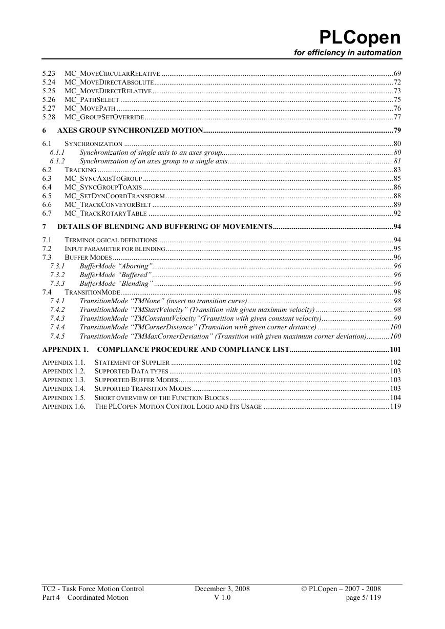
PLCopen 6.1.1 6.1.2 7.4 for efficiency in automation 5.23 MC_MOVECIRCULARRELATIVE ...........................................................................................................................69 5.24 MC_MOVEDIRECTABSOLUTE...............................................................................................................................72 5.25 MC_MOVEDIRECTRELATIVE................................................................................................................................73 5.26 MC_PATHSELECT .................................................................................................................................................75 5.27 MC_MOVEPATH ...................................................................................................................................................76 5.28 MC_GROUPSETOVERRIDE....................................................................................................................................77 6 AXES GROUP SYNCHRONIZED MOTION.....................................................................................................79 SYNCHRONIZATION ...............................................................................................................................................80 6.1 Synchronization of single axis to an axes group...........................................................................................80 Synchronization of an axes group to a single axis........................................................................................81 TRACKING .............................................................................................................................................................83 6.2 6.3 MC_SYNCAXISTOGROUP.....................................................................................................................................85 6.4 MC_SYNCGROUPTOAXIS.....................................................................................................................................86 6.5 MC_SETDYNCOORDTRANSFORM.........................................................................................................................88 6.6 MC_TRACKCONVEYORBELT ................................................................................................................................89 6.7 MC_TRACKROTARYTABLE ..................................................................................................................................92 7 DETAILS OF BLENDING AND BUFFERING OF MOVEMENTS................................................................94 7.1 TERMINOLOGICAL DEFINITIONS.............................................................................................................................94 7.2 INPUT PARAMETER FOR BLENDING.........................................................................................................................95 BUFFER MODES .....................................................................................................................................................96 7.3 BufferMode “Aborting”................................................................................................................................96 BufferMode “Buffered” ................................................................................................................................96 BufferMode “Blending” ...............................................................................................................................96 TRANSITIONMODE.................................................................................................................................................98 TransitionMode “TMNone” (insert no transition curve) .............................................................................98 TransitionMode “TMStartVelocity” (Transition with given maximum velocity) .........................................98 TransitionMode “TMConstantVelocity”(Transition with given constant velocity)......................................99 TransitionMode “TMCornerDistance” (Transition with given corner distance) ......................................100 TransitionMode “TMMaxCornerDeviation” (Transition with given maximum corner deviation)............100 APPENDIX 1. COMPLIANCE PROCEDURE AND COMPLIANCE LIST.....................................................101 APPENDIX 1.1. STATEMENT OF SUPPLIER ....................................................................................................................102 APPENDIX 1.2. SUPPORTED DATA TYPES .....................................................................................................................103 APPENDIX 1.3. SUPPORTED BUFFER MODES................................................................................................................103 APPENDIX 1.4. SUPPORTED TRANSITION MODES.........................................................................................................103 APPENDIX 1.5. SHORT OVERVIEW OF THE FUNCTION BLOCKS.....................................................................................104 APPENDIX 1.6. THE PLCOPEN MOTION CONTROL LOGO AND ITS USAGE ...................................................................119 7.3.1 7.3.2 7.3.3 7.4.1 7.4.2 7.4.3 7.4.4 7.4.5 TC2 - Task Force Motion Control Part 4 – Coordinated Motion December 3, 2008 V 1.0 © PLCopen – 2007 - 2008 page 5/ 119
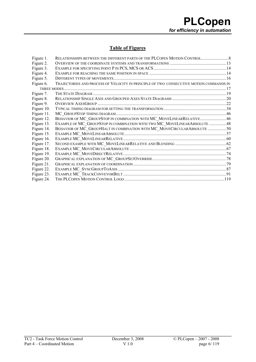
PLCopen for efficiency in automation Table of Figures Figure 1. Figure 2. Figure 3. Figure 4. Figure 5. Figure 6. RELATIONSHIPS BETWEEN THE DIFFERENT PARTS OF THE PLCOPEN MOTION CONTROL.........................8 OVERVIEW OF THE COORDINATE SYSTEMS AND TRANSFORMATIONS ....................................................13 EXAMPLE FOR SPECIFYING POINT P IN PCS, MCS OR ACS ...................................................................14 EXAMPLE FOR REACHING THE SAME POSITION IN SPACE .......................................................................14 DIFFERENT TYPES OF MOVEMENTS........................................................................................................16 TRAJECTORIES AND PROCESS OF VELOCITY IN PRINCIPLE OF TWO CONSECUTIVE MOTION COMMANDS IN THREE MODES......................................................................................................................................................17 THE STATE DIAGRAM ...........................................................................................................................19 Figure 7. RELATIONSHIP SINGLE AXIS AND GROUPED AXES STATE DIAGRAMS ..................................................20 Figure 8. OVERVIEW AXESGROUP.......................................................................................................................22 Figure 9. Figure 10. TYPICAL TIMING DIAGRAM FOR SETTING THE TRANSFORMATION..........................................................34 Figure 11. MC_GROUPSTOP TIMING DIAGRAM......................................................................................................46 Figure 12. BEHAVIOR OF MC_GROUPSTOP IN COMBINATION WITH MC_MOVELINEARRELATIVE........................46 Figure 13. EXAMPLE OF MC_GROUPSTOP IN COMBINATION WITH TWO MC_MOVELINEARABSOLUTE ................48 Figure 14. BEHAVIOR OF MC_GROUPHALT IN COMBINATION WITH MC_MOVECIRCULARABSOLUTE .................50 Figure 15. EXAMPLE MC_MOVELINEARABSOLUTE..............................................................................................57 Figure 16. EXAMPLE MC_MOVELINEARRELATIVE...............................................................................................60 Figure 17. SECOND EXAMPLE WITH MC_MOVELINEARRELATIVE AND BLENDING ...............................................62 Figure 18. EXAMPLE MC_MOVECIRCULARABSOLUTE .........................................................................................67 Figure 19. EXAMPLE MC_MOVEDIRECTRELATIVE...............................................................................................74 Figure 20. GRAPHICAL EXPLANATION OF MC_GROUPSETOVERRIDE....................................................................78 Figure 21. GRAPHICAL EXPLANATION OF COORDINATION......................................................................................79 Figure 22. EXAMPLE MC_SYNCGROUPTOAXIS ....................................................................................................87 Figure 23. EXAMPLE MC_TRACKCONVEYORBELT ...............................................................................................91 Figure 24. THE PLCOPEN MOTION CONTROL LOGO............................................................................................119 TC2 - Task Force Motion Control Part 4 – Coordinated Motion December 3, 2008 V 1.0 © PLCopen – 2007 - 2008 page 6/ 119
PLCopen for efficiency in automation Table of Tables 1. OVERVIEW OF THE DEFINED FUNCTION BLOCKS ...................................................................................................9 2. OVERVIEW OF BUFFER MODES............................................................................................................................17 3. OVERVIEW OF TRANSITION MODES.....................................................................................................................18 4. MATRIX OF AVAILABLE TRANSITION MODES .......................................................................................................18 5. OVERVIEW OF THE INFLUENCE OF GROUP MOTION COMMANDS ON A SINGLE AXIS STATE....................................21 6. OVERVIEW OF BUFFER MODES.............................................................................................................................96 7. OVERVIEW OF AVAILABLE TRANSITION MODES...................................................................................................98 8. SUPPORTED DATATYPES....................................................................................................................................103 9. SUPPORTED DERIVED DATATYPES .....................................................................................................................103 10. OVERVIEW OF BUFFER MODES...........................................................................................................................103 11. OVERVIEW OF AVAILABLE TRANSITION MODES.................................................................................................103 12. SHORT OVERVIEW OF THE FUNCTION BLOCKS ..................................................................................................104 TC2 - Task Force Motion Control Part 4 – Coordinated Motion December 3, 2008 V 1.0 © PLCopen – 2007 - 2008 page 7/ 119
PLCopen for efficiency in automation 1 General 1.1 Objectives The objective of this document is to define a set of extensions to “Part 1 - PLCopen Function Blocks for Motion Control”, as well as “Part 2 - Extensions” focused to the coordinated multi-axes motion in 3D space, to serve the majority of user’s application needs in this area. Part 1 and Part 2 deal with Master / slave motion control, a type of coordinated motion control where the master axis position is used to generate one or more slave axis position commands. For multi dimensional movements, one goes beyond this point via a grouping of a set of axes, without a master axis. This is done via the definition of a set of Function Blocks with related coordinated motion functionality as well as a higher level state diagram, linking the single axis state diagrams in the group. In this way a better trajectory planning is possible. Also, the current Master/Slave axes can have the problem that if an error occurs, the other axes have no knowledge about this, and continue their movement. By combining axes in a group one knows upfront which axes are involved and has the basis for a better error behavior. 1.2 Introduction The level of the PLCopen Motion Control Function Blocks are specified at such a level that the user quickly recognizes the functionality of the function block and what happens if it is activated or connected to other blocks in a sequence of motion commands. Path oriented movements are programmed either with specific robot oriented programming languages, or “G-code” (for instance cf. DIN 66025) as used in the CNC world. Both consist of a relative small number of users. But without a doubt, the movements which can be described in these languages are applicable to a broader area of use. This PLCopen initiative transforms the functionalities as known in the CNC and Robotic world to the PLC world. With this, an additional part is added to the range of PLCopen Motion Control specifications. The relationship with the other PLCopen parts is shown below. y´ PCS MCS ACS Functions of PLCopen Part 1 and 2 SAI SAI SAI Axis group 1 2 3 SAI = Single Axis Interpolator 1 2 3 Figure 1: Relationships between the different parts of the PLCopen Motion Control TC2 - Task Force Motion Control Part 4 – Coordinated Motion December 3, 2008 V 1.0 © PLCopen – 2007 - 2008 page 8/ 119
分享到:
收藏