VA-10/VA-11
Socket 462 System Board
User’s Manual
4200-0376-23
Rev. 1.01
�
Copyright and Warranty Notice
The information in this document is subject to change without notice and does not
represent a commitment on part of the vendor, who assumes no liability or
responsibility for any errors that may appear in this manual.
No warranty or representation, either expressed or implied, is made with respect to the
quality, accuracy or fitness for any particular part of this document. In no event shall
the manufacturer be liable for direct, indirect, special, incidental or consequential
damages arising from any defect or error in this manual or product.
Product names appearing in this manual are for identification purpose only and
trademarks and product names or brand names appearing in this document are
property of their respective owners.
This document contains materials protected under International Copyright Laws. All
rights reserved. No part of this manual may be reproduced, transmitted or transcribed
without the expressed written permission of the manufacturer and authors of this
manual.
VA-10/VA-11
�
Table Of Contents
Chapter 1.
Introduction .................................................... 1-1
1.1. Features & Specifications....................................................... 1-1
1.2. Layout Diagram...................................................................... 1-3
1.3.
Jumpers & Connectors Description........................................ 1-4
Chapter 2. Hardware Setup.............................................. 2-1
2.1. Precautions ............................................................................. 2-1
2.2.
Installing the System Board ................................................... 2-2
2.3.
Install CPU and Heatsink ....................................................... 2-3
2.4. System Memory ..................................................................... 2-5
2.4.1. Memory Configuration Table ................................... 2-5
2.4.2.
Installing and Removing Memory Modules............. 2-6
2.5. Connectors, Headers, and Switches ....................................... 2-7
2.5.1. ATX Power Connectors............................................ 2-7
2.5.2. FAN Connectors ....................................................... 2-8
2.5.3. CMOS Memory Clearing Header............................. 2-9
2.5.4. Accelerated Graphics Port Slot............................... 2-10
2.5.5. Front Panel Switches & Indicators Connection
Headers ................................................................... 2-11
Infrared Device Connection Header ....................... 2-12
2.5.6.
2.5.7. Additional USB Port Connection Header............... 2-13
2.5.8. Additional IEEE1394 Port Headers........................ 2-14
2.5.9.
Internal Audio Source Connectors ......................... 2-15
2.5.10. Floppy Disk Drive Connector................................. 2-16
2.5.11. IDE Disk Drive Connectors.................................... 2-17
2.5.12. External I/O Panel................................................... 2-18
Chapter 3. BIOS Setup...................................................... 3-1
3.1. Standard CMOS Features....................................................... 3-2
3.2. Advanced BIOS Features ....................................................... 3-6
3.3. Advanced Chipset Features .................................................... 3-8
User’s Manual
�
3.4.
Integrated Peripherals........................................................... 3-13
3.5. Power Management Setup.................................................... 3-19
3.6. PnP/PCI Configurations ....................................................... 3-21
3.7. PC Health Status................................................................... 3-23
3.8. Frequency/Voltage Control .................................................. 3-25
3.9. Load Fail-Safe Defaults........................................................ 3-26
3.10. Load Optimized Defaults ..................................................... 3-26
3.11. Set Supervisor Password ...................................................... 3-26
3.12. Set User Password ................................................................ 3-26
3.13. Save & Exit Setup ................................................................ 3-26
3.14. Exit Without Saving ............................................................. 3-26
Chapter 4. Driver Installation .......................................... 4-1
4.1. Setup Items ............................................................................. 4-2
Appendix A. How to Get Technical Support ..................... A-1
VA-10/VA-11
�
Introduction
1-1
Chapter 1.
Introduction
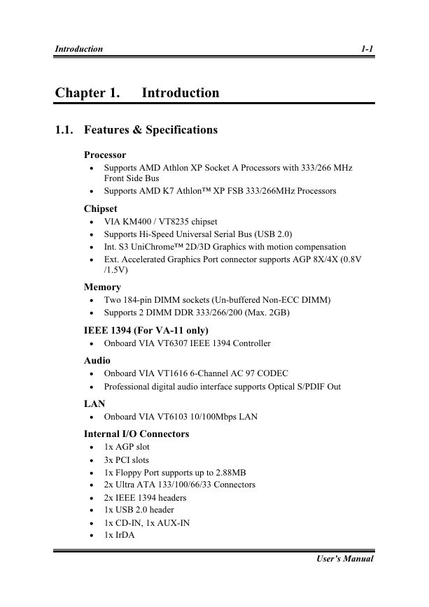
1.1. Features & Specifications
Processor
Supports AMD Athlon XP Socket A Processors with 333/266 MHz
Front Side Bus
Supports AMD K7 Athlon™ XP FSB 333/266MHz Processors
Chipset
VIA KM400 / VT8235 chipset
Supports Hi-Speed Universal Serial Bus (USB 2.0)
Int. S3 UniChrome™ 2D/3D Graphics with motion compensation
Ext. Accelerated Graphics Port connector supports AGP 8X/4X (0.8V
/1.5V)
Memory
Two 184-pin DIMM sockets (Un-buffered Non-ECC DIMM)
Supports 2 DIMM DDR 333/266/200 (Max. 2GB)
IEEE 1394 (For VA-11 only)
Onboard VIA VT6307 IEEE 1394 Controller
Audio
Onboard VIA VT1616 6-Channel AC 97 CODEC
Professional digital audio interface supports Optical S/PDIF Out
LAN
Onboard VIA VT6103 10/100Mbps LAN
Internal I/O Connectors
1x AGP slot
3x PCI slots
1x Floppy Port supports up to 2.88MB
2x Ultra ATA 133/100/66/33 Connectors
2x IEEE 1394 headers
1x USB 2.0 header
1x CD-IN, 1x AUX-IN
1x IrDA
User’s Manual
�
1-2
Chapter 1
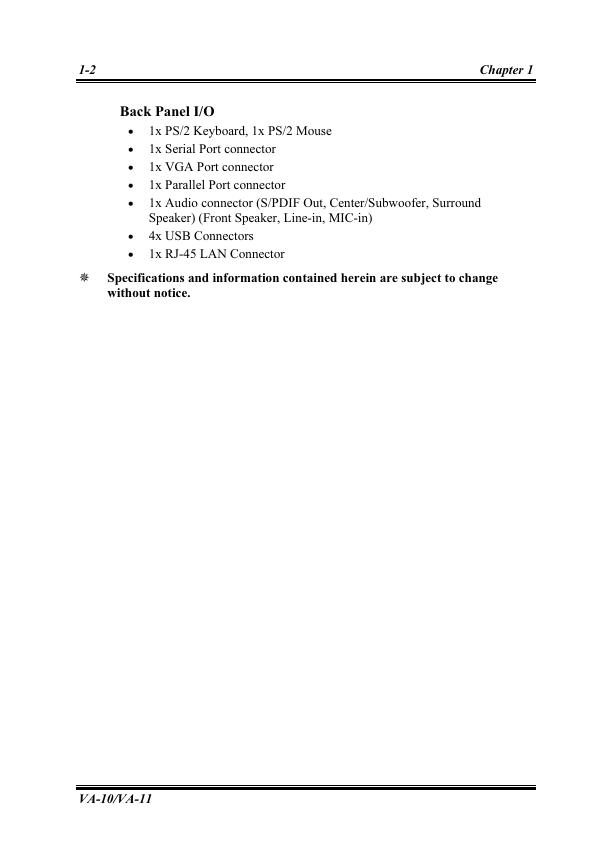
Back Panel I/O
1x PS/2 Keyboard, 1x PS/2 Mouse
1x Serial Port connector
1x VGA Port connector
1x Parallel Port connector
1x Audio connector (S/PDIF Out, Center/Subwoofer, Surround
Speaker) (Front Speaker, Line-in, MIC-in)
4x USB Connectors
1x RJ-45 LAN Connector
� Specifications and information contained herein are subject to change
without notice.
VA-10/VA-11
�
Introduction
1-3
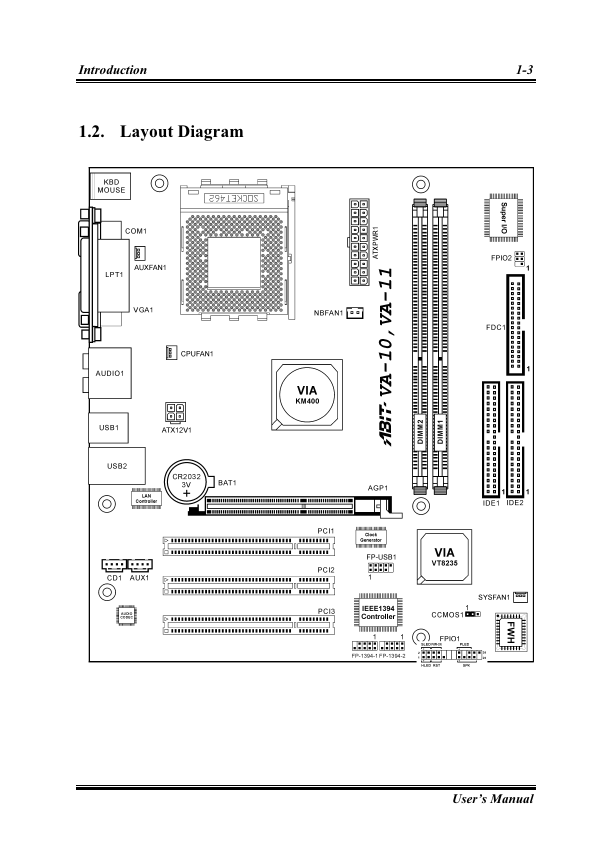
1.2. Layout Diagram
User’s Manual
�
1-4
Chapter 1
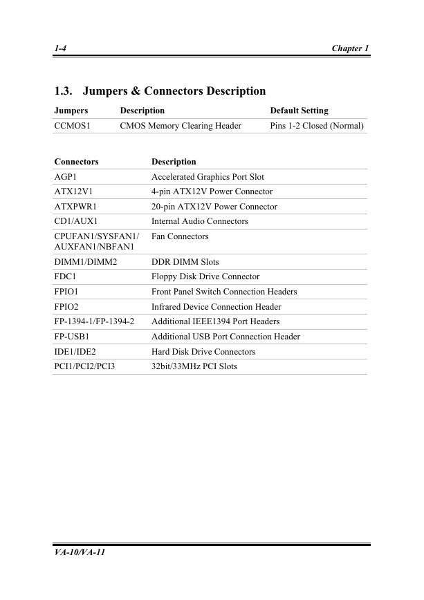
1.3. Jumpers & Connectors Description
Jumpers
Description
Default Setting
CCMOS1
CMOS Memory Clearing Header
Pins 1-2 Closed (Normal)
Connectors
Description
AGP1
ATX12V1
ATXPWR1
CD1/AUX1
Accelerated Graphics Port Slot
4-pin ATX12V Power Connector
20-pin ATX12V Power Connector
Internal Audio Connectors
CPUFAN1/SYSFAN1/
AUXFAN1/NBFAN1
Fan Connectors
DIMM1/DIMM2
DDR DIMM Slots
FDC1
FPIO1
FPIO2
Floppy Disk Drive Connector
Front Panel Switch Connection Headers
Infrared Device Connection Header
FP-1394-1/FP-1394-2
Additional IEEE1394 Port Headers
FP-USB1
IDE1/IDE2
Additional USB Port Connection Header
Hard Disk Drive Connectors
PCI1/PCI2/PCI3
32bit/33MHz PCI Slots
VA-10/VA-11
�



 2023年江西萍乡中考道德与法治真题及答案.doc
 2012年重庆南川中考生物真题及答案.doc
 2013年江西师范大学地理学综合及文艺理论基础考研真题.doc
 2020年四川甘孜小升初语文真题及答案I卷.doc
 2020年注册岩土工程师专业基础考试真题及答案.doc
 2023-2024学年福建省厦门市九年级上学期数学月考试题及答案.doc
 2021-2022学年辽宁省沈阳市大东区九年级上学期语文期末试题及答案.doc
 2022-2023学年北京东城区初三第一学期物理期末试卷及答案.doc
 2018上半年江西教师资格初中地理学科知识与教学能力真题及答案.doc
 2012年河北国家公务员申论考试真题及答案-省级.doc
 2020-2021学年江苏省扬州市江都区邵樊片九年级上学期数学第一次质量检测试题及答案.doc
 2022下半年黑龙江教师资格证中学综合素质真题及答案.doc