MLX90641 16x12 IR array
Datasheet
1. Features and Benefits
Small size, low cost 16x12 pixels IR array
2. Application Examples
High precision non-contact temperature
Easy to integrate
Industry standard four lead TO39 package
Factory calibrated
Noise Equivalent Temperature Difference
(NETD) 0.1K @4Hz refresh rate
I2C compatible digital interface
Programmable refresh rate 0.5Hz…64Hz
3.3V supply voltage
Current consumption ≈ 12mA
2 FOV options – 55°x35° and 110°x75°
Operating temperature -40°C ÷ 125°C
Target temperature -40°C ÷ 300°C
Complies with RoHS regulations
measurements
Microwave ovens
Intrusion / Movement detection
Temperature sensing element for
residential, commercial and industrial
building air conditioning
Thermal Comfort sensor in automotive Air
Conditioning control system
Passenger classification
Industrial temperature control of moving
parts
Visual IR thermometers
Driver SW for MCU available at:
https://github.com/melexis/mlx90641-
library.git
3. Description
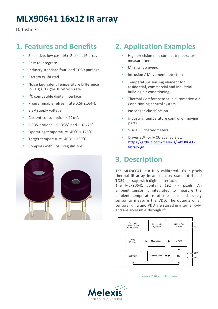
The MLX90641 is a fully calibrated 16x12 pixels
thermal IR array in an industry standard 4-lead
TO39 package with digital interface.
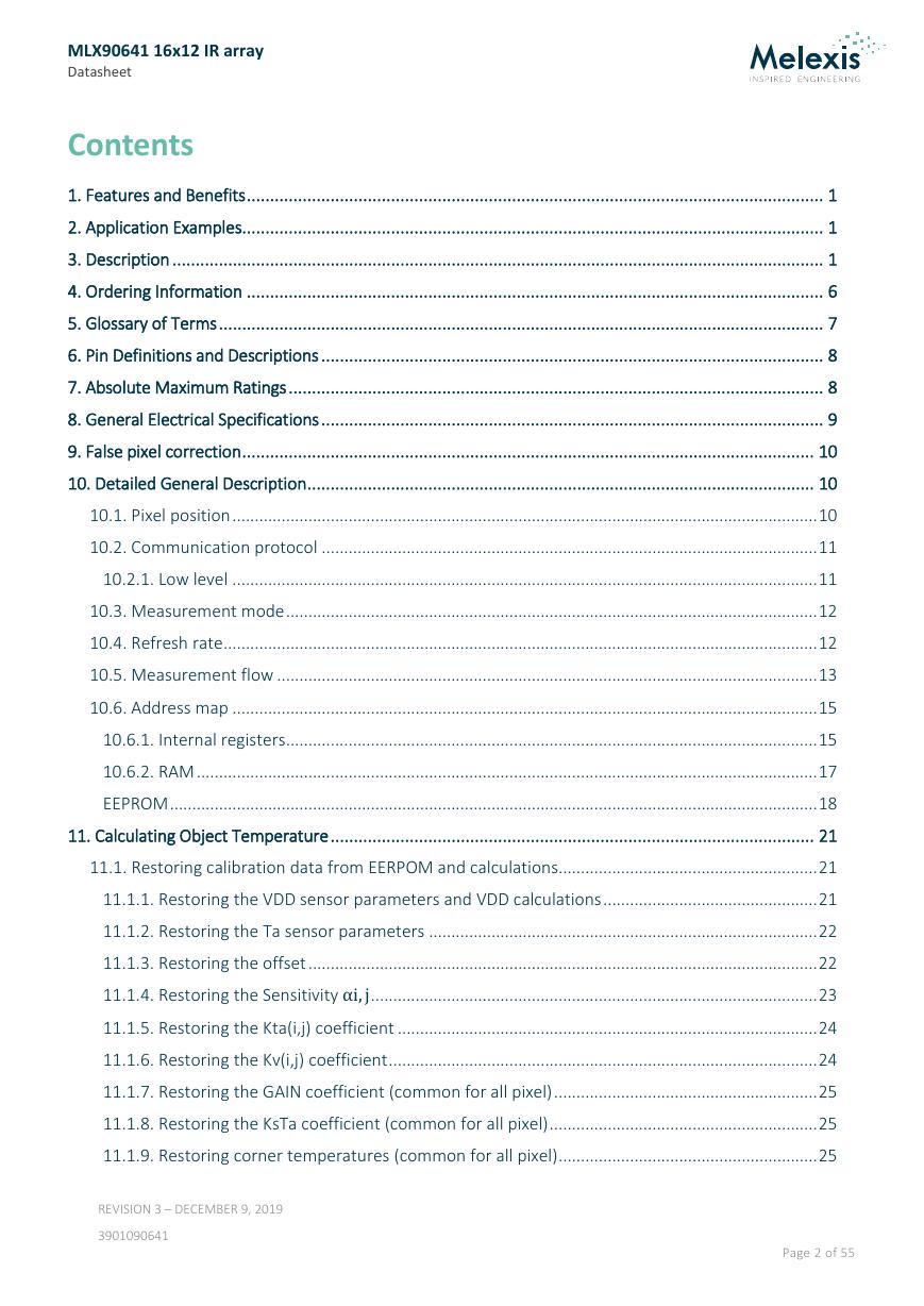
The MLX90641 contains 192 FIR pixels. An
ambient sensor is integrated to measure the
ambient temperature of the chip and supply
sensor to measure the VDD. The outputs of all
sensors IR, Ta and VDD are stored in internal RAM
and are accessible through I2C.
Figure 1 Block diagram
ArrayM pixelsSDABand gap reference and PTAT sensorEEPROMI2CSCLM amplifiersM ADCRegulator for digital part34 MHz RC oscillatorStorage RAMVssVdd�
MLX90641 16x12 IR array
Datasheet
Contents
1. Features and Benefits ............................................................................................................................ 1
2. Application Examples ............................................................................................................................. 1
3. Description ............................................................................................................................................ 1
4. Ordering Information ............................................................................................................................ 6
5. Glossary of Terms .................................................................................................................................. 7
6. Pin Definitions and Descriptions ............................................................................................................ 8
7. Absolute Maximum Ratings ................................................................................................................... 8
8. General Electrical Specifications ............................................................................................................ 9
9. False pixel correction ........................................................................................................................... 10
10. Detailed General Description ............................................................................................................. 10
10.1. Pixel position ................................................................................................................................... 10
10.2. Communication protocol ............................................................................................................... 11
10.2.1. Low level ................................................................................................................................... 11
10.3. Measurement mode ....................................................................................................................... 12
10.4. Refresh rate ..................................................................................................................................... 12
10.5. Measurement flow ......................................................................................................................... 13
10.6. Address map ................................................................................................................................... 15
10.6.1. Internal registers....................................................................................................................... 15
10.6.2. RAM ........................................................................................................................................... 17
EEPROM ................................................................................................................................................. 18
11. Calculating Object Temperature ........................................................................................................ 21
11.1. Restoring calibration data from EERPOM and calculations.......................................................... 21
11.1.1. Restoring the VDD sensor parameters and VDD calculations ................................................ 21
11.1.2. Restoring the Ta sensor parameters ....................................................................................... 22
11.1.3. Restoring the offset .................................................................................................................. 22
11.1.4. Restoring the Sensitivity .................................................................................................... 23
11.1.5. Restoring the Kta(i,j) coefficient .............................................................................................. 24
11.1.6. Restoring the Kv(i,j) coefficient ................................................................................................ 24
11.1.7. Restoring the GAIN coefficient (common for all pixel) ........................................................... 25
11.1.8. Restoring the KsTa coefficient (common for all pixel) ............................................................ 25
11.1.9. Restoring corner temperatures (common for all pixel) .......................................................... 25
REVISION 3 – DECEMBER 9, 2019
3901090641
Page 2 of 55
�
MLX90641 16x12 IR array
Datasheet
11.1.10. Restoring the KsTo coefficient
(common for all pixel) .................................... 25
11.1.11. Restoring sensitivity correction coefficients for each temperature range ......................... 26
11.1.12. Restoring Emissivity ................................................................................................................ 26
11.1.13. Restoring the Sensitivity ................................................................................................. 27
11.1.14. Restoring the offset of the CP ................................................................................................ 27
11.1.15. Restoring the Kv CP coefficient .............................................................................................. 27
11.1.16. Restoring the Kta CP coefficient ............................................................................................ 27
11.1.17. Restoring the TGC coefficient ................................................................................................ 27
11.1.18. Restoring calibration resolution control settings ................................................................. 28
11.2. Temperature calculation ................................................................................................................ 28
11.2.1. Example input data ................................................................................................................... 28
11.2.2. Temperature calculation .......................................................................................................... 31
12. Performance graphs .......................................................................................................................... 42
12.1. Accuracy .......................................................................................................................................... 42
12.1.1. Pixel accuracy ............................................................................................................................ 42
12.1.2. Ta accuracy ............................................................................................................................... 43
12.2. Startup time .................................................................................................................................... 44
12.2.1. First valid data ........................................................................................................................... 44
12.2.2. Thermal behavior...................................................................................................................... 44
12.3. Noise performance and resolution ................................................................................................ 45
12.4. Field of view (FOV) .......................................................................................................................... 47
13. Application information ..................................................................................................................... 48
13.1. Optical considerations .................................................................................................................... 48
13.2. Electrical considerations ................................................................................................................ 48
13.3. Using the device in “image mode” ................................................................................................ 49
14. Application Comments ...................................................................................................................... 50
15. Mechanical drawings ......................................................................................................................... 51
15.1. FOV 55° ............................................................................................................................................ 51
15.2. FOV 110° ......................................................................................................................................... 52
15.3. Device marking ............................................................................................................................... 53
16. Standard Information ........................................................................................................................ 54
17. ESD Precautions ................................................................................................................................. 54
18. Revision History Table ....................................................................................................................... 54
REVISION 3 – DECEMBER 9, 2019
3901090641
Page 3 of 55
�
MLX90641 16x12 IR array
Datasheet
19. Contact .............................................................................................................................................. 55
20. Disclaimer .......................................................................................................................................... 55
Tables
Table 1 Ordering information .......................................................................................................................................................... 6
Table 2 Glosarry of terms ................................................................................................................................................................ 7
Table 3 Pin definition ...................................................................................................................................................................... 8
Table 4 Absolute maximum ratings ................................................................................................................................................. 8
Table 5 Electrical specification ........................................................................................................................................................ 9
Table 6 Priorities of subpage controls ............................................................................................................................................16
Table 7 Configuration parameters memory ....................................................................................................................................18
Table 8 EEPROM overview (words) .................................................................................................................................................19
Table 9 Calibration parameters memory (EEPROM - bits) ...............................................................................................................20
Table 10 Calculation example input data ........................................................................................................................................28
Table 11 Calculation example calibration data ................................................................................................................................30
Table 12 Noise performance ..........................................................................................................................................................46
Table 13 Available FOV options ......................................................................................................................................................47
Table 14 Revision history ...............................................................................................................................................................54
Figures
Figure 1 Block diagram ................................................................................................................................................................... 1
Figure 2 MLX90641 Overview and pin description ........................................................................................................................... 8
Figure 3 Pixel in the whole FOV ......................................................................................................................................................10
Figure 4 I2C write command format (default SA=0x33 is used) ........................................................................................................11
Figure 5 I2C read command format (default SA=0x33 is used) .........................................................................................................11
Figure 6 Refresh rate timing ...........................................................................................................................................................12
Figure 7 Recommended measurement flow ...................................................................................................................................13
Figure 8 TV mode reading pattern ..................................................................................................................................................14
Figure 9 MXL90641 memory map ...................................................................................................................................................15
Figure 10 Status register (0x8000) bits meaning .............................................................................................................................15
Figure 11 Control register 1 (0x800D) bits meaning ........................................................................................................................16
Figure 12 I2C configuration register (0x800F) bits meaning .............................................................................................................17
Figure 13 RAM memory map (Interleaved mode - default) ..............................................................................................................17
Figure 14 EEPROM to registers mapping .........................................................................................................................................18
Figure 15 EEPROM Hamming and data bit meaning ........................................................................................................................21
Figure 16 To calculation flow .........................................................................................................................................................31
Figure 17 Temperature absolute accuracy - MLX90641BCA .............................................................................................................42
Figure 18 Temperature absolute accuracy - MLX90641BCB .............................................................................................................43
Figure 19 Different accuracy zones depending on device type (BCA on the left and BCB on the right) ..............................................43
Figure 20 MLX90641BCx noise vs refresh rate for different device types .........................................................................................45
Figure 21 MLX90641BCA noise vs pixel and refresh rate at 1Hz and 2Hz .........................................................................................45
Figure 22 MLX90641BCA noise vs pixel and refresh rate at 4Hz, 8Hz and 16Hz ................................................................................45
REVISION 3 – DECEMBER 9, 2019
3901090641
Page 4 of 55
�
MLX90641 16x12 IR array
Datasheet
Figure 23 MLX90641BCB noise vs pixel and refresh rate at 1Hz and 2Hz..........................................................................................46
Figure 24 MLX90641BCB noise vs pixel and refresh rate at 4Hz, 8Hz and 16Hz ................................................................................46
Figure 25 Field Of View measurement ............................................................................................................................................47
Figure 26 Application examples concerning the optical consideration .............................................................................................48
Figure 27 MLX90641Bxx electrical connections...............................................................................................................................48
Figure 28 Calculation flow in thermal image mode .........................................................................................................................49
Figure 29 Mechanical drawing of 55° FOV device ............................................................................................................................51
Figure 30 Mechanical drawing of 110° FOV device ..........................................................................................................................52
REVISION 3 – DECEMBER 9, 2019
3901090641
Page 5 of 55
�
MLX90641 16x12 IR array
Datasheet
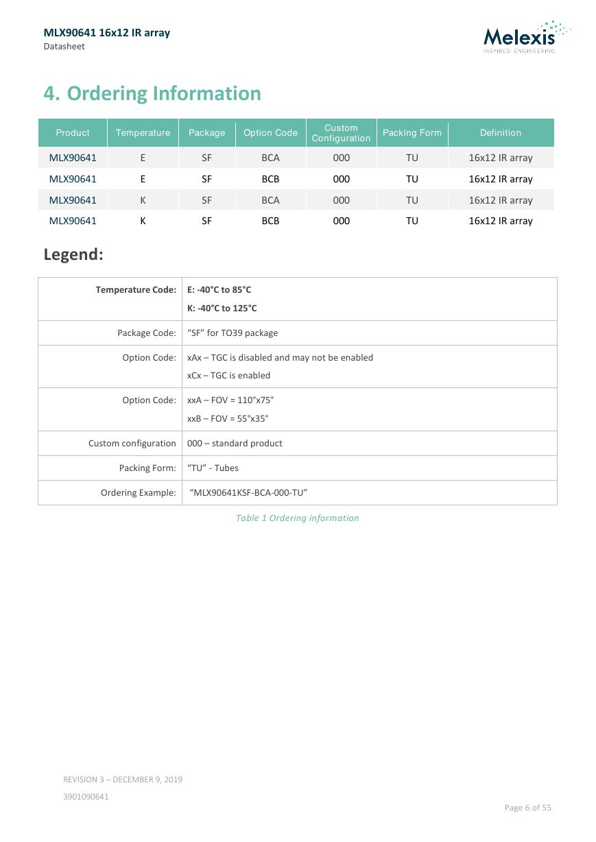
4. Ordering Information
Product
Temperature
Package
Option Code
Custom
Configuration
Packing Form
Definition
E
E
K
K
MLX90641
MLX90641
MLX90641
MLX90641
Legend:
SF
SF
SF
SF
BCA
BCB
BCA
BCB
000
000
000
000
TU
TU
TU
TU
16x12 IR array
16x12 IR array
16x12 IR array
16x12 IR array
Temperature Code: E: -40°C to 85°C
K: -40°C to 125°C
Package Code:
“SF” for TO39 package
Option Code: xAx – TGC is disabled and may not be enabled
xCx – TGC is enabled
Option Code: xxA – FOV = 110°x75°
xxB – FOV = 55°x35°
Custom configuration 000 – standard product
Packing Form:
“TU” - Tubes
Ordering Example:
“MLX90641KSF-BCA-000-TU”
Table 1 Ordering information
REVISION 3 – DECEMBER 9, 2019
3901090641
Page 6 of 55
�
MLX90641 16x12 IR array
Datasheet
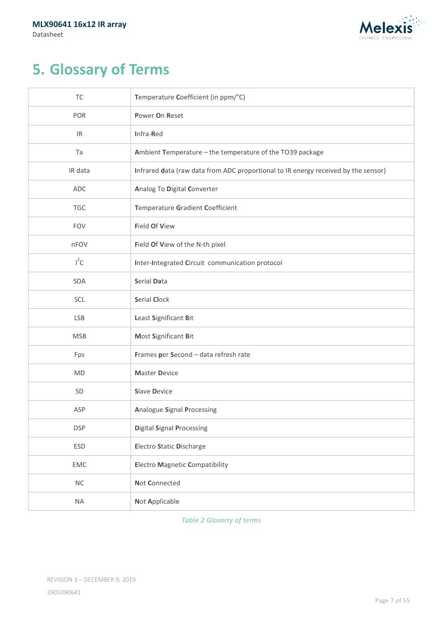
5. Glossary of Terms
TC
POR
IR
Ta
Temperature Coefficient (in ppm/°C)
Power On Reset
Infra-Red
Ambient Temperature – the temperature of the TO39 package
IR data
Infrared data (raw data from ADC proportional to IR energy received by the sensor)
ADC
TGC
FOV
Analog To Digital Converter
Temperature Gradient Coefficient
Field Of View
nFOV
Field Of View of the N-th pixel
I2C
SDA
SCL
LSB
MSB
Fps
MD
SD
ASP
DSP
ESD
EMC
NC
NA
Inter-Integrated Circuit communication protocol
Serial Data
Serial Clock
Least Significant Bit
Most Significant Bit
Frames per Second – data refresh rate
Master Device
Slave Device
Analogue Signal Processing
Digital Signal Processing
Electro Static Discharge
Electro Magnetic Compatibility
Not Connected
Not Applicable
Table 2 Glosarry of terms
REVISION 3 – DECEMBER 9, 2019
3901090641
Page 7 of 55
�
MLX90641 16x12 IR array
Datasheet
6. Pin Definitions and Descriptions
Pin #
1
2
3
4
Name
SDA
VDD
GND
SCL
Description
I2C serial data (input / output)
Positive supply
Negative supply (Ground)
I2C serial clock (input only)
Table 3 Pin definition
Figure 2 MLX90641 Overview and pin description
7. Absolute Maximum Ratings
Parameter
Symbol Min.
Typ.
Max.
Unit
Remark
Supply Voltage (over voltage)
Supply Voltage (operating max voltage)
Reverse Voltage (each pin)
Operating Temperature
Storage Temperature
ESD sensitivity (AEC Q100 002)
SDA DC sink current
VDD
VDD
TAMB
TST
-40
-40
4
5
3.6
-0.3
+125
+150
40
V
V
°C
°C
kV
mA
Table 4 Absolute maximum ratings
Not in plastic tubes
Exceeding the absolute maximum ratings may cause permanent damage. Exposure to absolute maximum-
rated conditions for extended periods may affect device reliability.
REVISION 3 – DECEMBER 9, 2019
3901090641
Page 8 of 55
�




 V2版本原理图(Capacitive-Fingerprint-Reader-Schematic_V2).pdf
 摄像头工作原理.doc
 VL53L0X简要说明(En.FLVL53L00216).pdf
 原理图(DVK720-Schematic).pdf
 原理图(Pico-Clock-Green-Schdoc).pdf
 原理图(RS485-CAN-HAT-B-schematic).pdf
 File:SIM7500_SIM7600_SIM7800 Series_SSL_Application Note_V2.00.pdf
 ADS1263(Ads1262).pdf
 原理图(Open429Z-D-Schematic).pdf
 用户手册(Capacitive_Fingerprint_Reader_User_Manual_CN).pdf
 CY7C68013A(英文版)(CY7C68013A).pdf
 TechnicalReference_Dem.pdf